
Maintenance Manual
Page 5
... used , hold down the first two and at the same time press Pause (Break). For example: Read Only Memory (ROM) Keys Keys are enclosed in the boldface type below : Format complete System transferred Tecra A3/S2 Maintenance Manual v If three keys are instructed to describe many operations. Key operation Some operations require you...
... used , hold down the first two and at the same time press Pause (Break). For example: Read Only Memory (ROM) Keys Keys are enclosed in the boldface type below : Format complete System transferred Tecra A3/S2 Maintenance Manual v If three keys are instructed to describe many operations. Key operation Some operations require you...
Maintenance Manual
Page 8
Chapter 4 Replacement Procedures 4.1 General ...4-1 4.2 Battery ...4-7 4.3 PC Card ...4-8 4.4 HDD ...4-9 4.5 Optical Drive Module...4-12 4.6 Optical Drive ...4-13 4.7 Wireless LAN...4-15 4.8 Expansion Memory ...4-17 4.9 Keyboard ...4-21 4.10 Bluetooth ...4-21 4.11 Modem...4-25 4.12 Display Assembly...4-26 4.13 Top Cover...4-28 4.14 Touch Pad...4-31 4.15 Speakers...4-32 4.16 System Board ...4-33 4.17 Direct Play buttom board 4-36 4.18 Fan, Hest & CPU...4-37 4.19 Display Mask...4-38 4.20 LCD Module...4-42 4.21 FL Inverter Board...4-44 viii Tecra A3/S2 Maintenance Manual
Chapter 4 Replacement Procedures 4.1 General ...4-1 4.2 Battery ...4-7 4.3 PC Card ...4-8 4.4 HDD ...4-9 4.5 Optical Drive Module...4-12 4.6 Optical Drive ...4-13 4.7 Wireless LAN...4-15 4.8 Expansion Memory ...4-17 4.9 Keyboard ...4-21 4.10 Bluetooth ...4-21 4.11 Modem...4-25 4.12 Display Assembly...4-26 4.13 Top Cover...4-28 4.14 Touch Pad...4-31 4.15 Speakers...4-32 4.16 System Board ...4-33 4.17 Direct Play buttom board 4-36 4.18 Fan, Hest & CPU...4-37 4.19 Display Mask...4-38 4.20 LCD Module...4-42 4.21 FL Inverter Board...4-44 viii Tecra A3/S2 Maintenance Manual
Maintenance Manual
Page 14
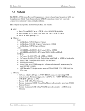
... Intel 915GM/ 910GML. • NVIDIA and ATI Graphic model, external 32/64/128MB VGA DDR RAM for 128MB System Memory Tecra A3/S2 Series Maintenance Manual 1-5 NVIDIA: • GeForceTM Go 6600 GPU with 64MB or 128MB • GeForceTM Go 6200 GPU with Turbo Cache with 32MB or ...
... Intel 915GM/ 910GML. • NVIDIA and ATI Graphic model, external 32/64/128MB VGA DDR RAM for 128MB System Memory Tecra A3/S2 Series Maintenance Manual 1-5 NVIDIA: • GeForceTM Go 6600 GPU with 64MB or 128MB • GeForceTM Go 6200 GPU with Turbo Cache with 32MB or ...
Maintenance Manual
Page 17
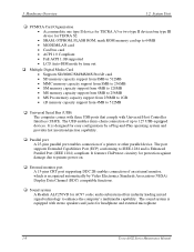
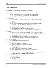
... to enhance the computer's multimedia capability. The sound system is equipped with stereo speakers and jacks for TECRA S2. • SRAM, OTPROM, FLASH ROM, mask ROM memory card up to printer power-on. ‰ External monitor port A 15-pins CRT port supporting DDC...Hardware Overview 1.2 System Unit ‰ PCMCIA Card Organization • Accommodate one type II device for TECRA A3 or two type II devices/one type III device for headphone and external microphone 1-8 Tecra A3/S2 Series Maintenance Manual The USB enables daisy-chain connection of a printer or other parallel device....
... to enhance the computer's multimedia capability. The sound system is equipped with stereo speakers and jacks for TECRA S2. • SRAM, OTPROM, FLASH ROM, mask ROM memory card up to printer power-on. ‰ External monitor port A 15-pins CRT port supporting DDC...Hardware Overview 1.2 System Unit ‰ PCMCIA Card Organization • Accommodate one type II device for TECRA A3 or two type II devices/one type III device for headphone and external microphone 1-8 Tecra A3/S2 Series Maintenance Manual The USB enables daisy-chain connection of a printer or other parallel device....
Maintenance Manual
Page 19
... with frequency range from North Bridge. ‰ Fixed Disk Interface • Marvell 88SA8040 supports PATA HDD. ‰ Video Subsystem • UMA VGA Memory up to 128MB • Display Core Frequency of the following major components: ‰ Processor • Intel Celeron M CPU up to 1.5GHz 0.09u... • 1MB/2MB L2 Cache on CPU • Support 64MB/128MB VGA memory for 10/100M LAN ‰ Memory • On board with LPC Interface • PC99a, PC2001 • ACPI 2.0 Compliant • Serial Ports • One Full Function Serial Port 1-10 Tecra A3/S2 Series Maintenance Manual
... with frequency range from North Bridge. ‰ Fixed Disk Interface • Marvell 88SA8040 supports PATA HDD. ‰ Video Subsystem • UMA VGA Memory up to 128MB • Display Core Frequency of the following major components: ‰ Processor • Intel Celeron M CPU up to 1.5GHz 0.09u... • 1MB/2MB L2 Cache on CPU • Support 64MB/128MB VGA memory for 10/100M LAN ‰ Memory • On board with LPC Interface • PC99a, PC2001 • ACPI 2.0 Compliant • Serial Ports • One Full Function Serial Port 1-10 Tecra A3/S2 Series Maintenance Manual
Maintenance Manual
Page 31
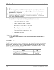
... is consuming. Use of power the system is powered on ) Data preservation period (full charge) Time About 24 hours 1 month 1-22 Tecra A3/S2 Series Maintenance Manual If any of full charge A full charge is detected from the battery pack through SMBus when the battery is charging.... removed. 3. The battery SMBus communication fails. 6. Overcharging could cause the battery to keep the current date, time and other setup information in memory while the computer is bad. ‰ Detection of the following occurs, the battery quick charge process stops. 1. The battery or output voltage is...
... is consuming. Use of power the system is powered on ) Data preservation period (full charge) Time About 24 hours 1 month 1-22 Tecra A3/S2 Series Maintenance Manual If any of full charge A full charge is detected from the battery pack through SMBus when the battery is charging.... removed. 3. The battery SMBus communication fails. 6. Overcharging could cause the battery to keep the current date, time and other setup information in memory while the computer is bad. ‰ Detection of the following occurs, the battery quick charge process stops. 1. The battery or output voltage is...
Maintenance Manual
Page 81
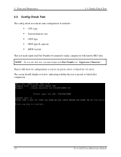
...is correct (in green color) or failed (in red color). Then it will show its configuration is passed or failed after comparison. 3-6 Tecra A3/S2 Series Maintenance Manual The screen should display as "Uppercase Character". Tests and Diagnostics 3.3 Config Check Test 3.3 Config Check Test The config... check test checks unit configuration. It includes: Š CPU type Š System memory size Š ODD type Š HDD type & capacity Š BIOS version This test needs input unit Part Number by manual to make ...
...is correct (in green color) or failed (in red color). Then it will show its configuration is passed or failed after comparison. 3-6 Tecra A3/S2 Series Maintenance Manual The screen should display as "Uppercase Character". Tests and Diagnostics 3.3 Config Check Test 3.3 Config Check Test The config... check test checks unit configuration. It includes: Š CPU type Š System memory size Š ODD type Š HDD type & capacity Š BIOS version This test needs input unit Part Number by manual to make ...
Maintenance Manual
Page 105
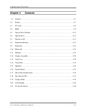
4 Replacement Procedures Chapter 4 Contents 4.1 General...4-1 4.2 Battery...4-7 4.3 PC Card...4-8 4.4 HDD...4-9 4.5 Optical Drive Module ...4-12 4.6 Optical Drive...4-13 4.7 Wireless LAN ...4-15 4.8 Expansion Memory...4-17 4.9 Keyboard...4-21 4.10 Bluetooth...4-21 4.11 Modem ...4-25 4.12 Display Assembly ...4-26 4.13 Top Cover ...4-28 4.14 Touch Pad ...4-31 4.15 Speakers ...4-32 4.16 System Board ...4-33 4.17 Direct Play buttom board 4-36 4.18 Fan, Hest & CPU ...4-37 4.19 Display Mask ...4-38 4.20 LCD Module ...4-42 4.21 FL Inverter Board ...4-44 Tecra A3/S2 Series Maintenance Manual 4-iii
4 Replacement Procedures Chapter 4 Contents 4.1 General...4-1 4.2 Battery...4-7 4.3 PC Card...4-8 4.4 HDD...4-9 4.5 Optical Drive Module ...4-12 4.6 Optical Drive...4-13 4.7 Wireless LAN ...4-15 4.8 Expansion Memory...4-17 4.9 Keyboard...4-21 4.10 Bluetooth...4-21 4.11 Modem ...4-25 4.12 Display Assembly ...4-26 4.13 Top Cover ...4-28 4.14 Touch Pad ...4-31 4.15 Speakers ...4-32 4.16 System Board ...4-33 4.17 Direct Play buttom board 4-36 4.18 Fan, Hest & CPU ...4-37 4.19 Display Mask ...4-38 4.20 LCD Module ...4-42 4.21 FL Inverter Board ...4-44 Tecra A3/S2 Series Maintenance Manual 4-iii
Maintenance Manual
Page 106
... wireless LAN cover 4-15 Figure 4-11 Removing the wireless LAN unit 4-16 Figure 4-12 Removing memory module cover 4-17 Figure 4-13 Removing a memory module 4-18 Figure 4-14 Removing an expansion memory cover 4-19 Figure 4-15 Installing an expansion memory 4-20 Figure 4-16 Removing the strip cover 4-21 Figure 4-17 Removing the keyboard 4-22 Figure... screw of bottom 4-28 Figure 4-24 Removing the top cover 4-29 Figure 4-25 Removing FFC cable 4-29 Figure 4-26 Removing the speakers cable 4-30 4-iv Tecra A3/S2 Series Maintenance Manual
... wireless LAN cover 4-15 Figure 4-11 Removing the wireless LAN unit 4-16 Figure 4-12 Removing memory module cover 4-17 Figure 4-13 Removing a memory module 4-18 Figure 4-14 Removing an expansion memory cover 4-19 Figure 4-15 Installing an expansion memory 4-20 Figure 4-16 Removing the strip cover 4-21 Figure 4-17 Removing the keyboard 4-22 Figure... screw of bottom 4-28 Figure 4-24 Removing the top cover 4-29 Figure 4-25 Removing FFC cable 4-29 Figure 4-26 Removing the speakers cable 4-30 4-iv Tecra A3/S2 Series Maintenance Manual
Maintenance Manual
Page 108
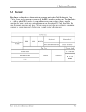
... 4.1 General This chapter explains how to the example on the following page. Battery pack Expansion Memory HDD Module System Board ODD MODEM Keyboard Direct Play Button Board Top Cover Wireless LAN Display Assembly Display Mask LCD Module Fan & Heat Sink CPU Speakers Touch Pad FL Inverter Board Tecra A3/S2 Series Maintenance Manual 4-1
... 4.1 General This chapter explains how to the example on the following page. Battery pack Expansion Memory HDD Module System Board ODD MODEM Keyboard Direct Play Button Board Top Cover Wireless LAN Display Assembly Display Mask LCD Module Fan & Heat Sink CPU Speakers Touch Pad FL Inverter Board Tecra A3/S2 Series Maintenance Manual 4-1
Maintenance Manual
Page 109
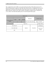
... in turn overlap the top cover. Battery pack Expansion Memory HDD Module ODD MODEM Keyboard Direct Play Button Board Wireless LAN Display Assembly System Board Top Cover Display Mask LCD Module Fan & Heat Sink CPU Speakers Touch Pad FL Inverter Board 4-2 Tecra A3/S2 Series Maintenance Manual Always starts the disassembly process by...
... in turn overlap the top cover. Battery pack Expansion Memory HDD Module ODD MODEM Keyboard Direct Play Button Board Wireless LAN Display Assembly System Board Top Cover Display Mask LCD Module Fan & Heat Sink CPU Speakers Touch Pad FL Inverter Board 4-2 Tecra A3/S2 Series Maintenance Manual Always starts the disassembly process by...
Maintenance Manual
Page 124
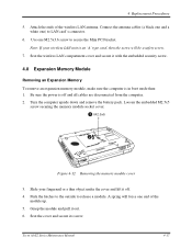
... cover. 1 M2.5x5 2 2 1 Figure 4-12 Removing the memory module cover 3. Seat the wireless LAN compartment cover and secure it off and all cables are disconnected from the computer. 2. Be sure the power is off . 4. Push the latches to the outside to LAN card's connector. 6. Tecra A3/S2 Series Maintenance Manual 4-17 Slide your...
... cover. 1 M2.5x5 2 2 1 Figure 4-12 Removing the memory module cover 3. Seat the wireless LAN compartment cover and secure it off and all cables are disconnected from the computer. 2. Be sure the power is off . 4. Push the latches to the outside to LAN card's connector. 6. Tecra A3/S2 Series Maintenance Manual 4-17 Slide your...
Maintenance Manual
Page 125
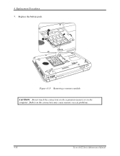
Debris on the computer. 4 Replacement Procedures 7. Replace the battery pack. 2 1 Latch Figure 4-13 Removing a memory module CAUTION: Do not touch the connectors on the expansion memory or on the connectors may cause memory access problems. 2 1 4-18 Tecra A3/S2 Series Maintenance Manual
Debris on the computer. 4 Replacement Procedures 7. Replace the battery pack. 2 1 Latch Figure 4-13 Removing a memory module CAUTION: Do not touch the connectors on the expansion memory or on the connectors may cause memory access problems. 2 1 4-18 Tecra A3/S2 Series Maintenance Manual
Maintenance Manual
Page 126
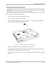
.... 6. Loosen the embedded M2.5x5 screw securing the memory module socket cover. 1 M2.5x5 2 2 1 Figure 4-14 Removing an expansion memory cover 4. Debris on either side will click into the computer's connectors at about a 45-degree angle and press the module carefully to the computer. 3. Tecra A3/S2 Series Maintenance Manual 4-19 4 Replacement Procedures Installing...
.... 6. Loosen the embedded M2.5x5 screw securing the memory module socket cover. 1 M2.5x5 2 2 1 Figure 4-14 Removing an expansion memory cover 4. Debris on either side will click into the computer's connectors at about a 45-degree angle and press the module carefully to the computer. 3. Tecra A3/S2 Series Maintenance Manual 4-19 4 Replacement Procedures Installing...
Maintenance Manual
Page 135
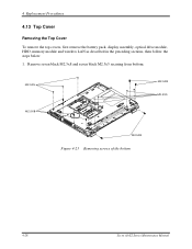
4 Replacement Procedures 4.13 Top Cover Removing the Top Cover To remove the top covers, first remove the battery pack, display assembly, optical drive module, HDD, memory module and wireless LAN as described in the preceding sections, then follow the steps below: 1. Remove seven black M2.5x8 and seven black M2.5x5 securing from bottom. M2.5X5 M2.5X8 M2.5X5 M2.5X8 M2.5X8 Figure 4-23 Removing screws of the bottom 4-28 Tecra A3/S2 Series Maintenance Manual
4 Replacement Procedures 4.13 Top Cover Removing the Top Cover To remove the top covers, first remove the battery pack, display assembly, optical drive module, HDD, memory module and wireless LAN as described in the preceding sections, then follow the steps below: 1. Remove seven black M2.5x8 and seven black M2.5x5 securing from bottom. M2.5X5 M2.5X8 M2.5X5 M2.5X8 M2.5X8 Figure 4-23 Removing screws of the bottom 4-28 Tecra A3/S2 Series Maintenance Manual
User Manual
Page 4
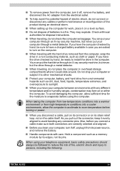
... baggage. When using the computer. If you move your telephone equipment, basic safety precautions should always be followed to persons, including the following: TECRA A3/S2 iv Do not drop your computer, turn on the cable itself. They may form on a level surface. ■ Do not dispose of... fire, electric shock and injury to reduce the risk of batteries in the computer. Hold a component such as a memory module by hand, be ready to room temperature before turning or power. ■ When you pull out the connector, keep it could slide around....
... baggage. When using the computer. If you move your telephone equipment, basic safety precautions should always be followed to persons, including the following: TECRA A3/S2 iv Do not drop your computer, turn on the cable itself. They may form on a level surface. ■ Do not dispose of... fire, electric shock and injury to reduce the risk of batteries in the computer. Hold a component such as a memory module by hand, be ready to room temperature before turning or power. ■ When you pull out the connector, keep it could slide around....

User Manual
Page 28
Chapter 8: Optional Devices PC cards 8-2 Installing a PC card 8-2 Removing a PC card 8-3 SD/MMC/SM/MS/MS Pro/xD Memory Cards 8-4 Installing a Memory card 8-4 Removing a Memory card 8-5 Memory card care 8-5 Memory expansion 8-6 Installing memory module 8-6 Removing memory module 8-8 Additional battery pack 8-9 Additional AC adaptor 8-9 Expansion port 8-10 External monitor 8-10 Television 8-10 i.LINK (IEEE1394 8-11 ...;RW drive (DVD Dual Drive 9-10 DVD Super Multi drive 9-11 Diskette drive 9-12 Sound system 9-12 PC Card 9-13 Printer 9-13 Memory cards 9-13 TECRA A3/S2 xxviii
Chapter 8: Optional Devices PC cards 8-2 Installing a PC card 8-2 Removing a PC card 8-3 SD/MMC/SM/MS/MS Pro/xD Memory Cards 8-4 Installing a Memory card 8-4 Removing a Memory card 8-5 Memory card care 8-5 Memory expansion 8-6 Installing memory module 8-6 Removing memory module 8-8 Additional battery pack 8-9 Additional AC adaptor 8-9 Expansion port 8-10 External monitor 8-10 Television 8-10 i.LINK (IEEE1394 8-11 ...;RW drive (DVD Dual Drive 9-10 DVD Super Multi drive 9-11 Diskette drive 9-12 Sound system 9-12 PC Card 9-13 Printer 9-13 Memory cards 9-13 TECRA A3/S2 xxviii
User Manual
Page 29
Pointing device 9-14 USB 9-15 Standby/Hibernation 9-15 Real Time Clock 9-16 Memory expansion 9-16 Modem 9-17 LAN 9-17 Wireless LAN 9-18 Monitor 9-18 Docking 9-18 i.LINK (IEEE1394 9-19 TOSHIBA support 9-19 Before you call 9-19 Where to write 9-19 Appendix A: Specifications Appendix B: Display Modes Appendix C: AC Power Cord and Connectors Appendix D: If your computer is stolen Glossary TECRA A3/S2 xxix
Pointing device 9-14 USB 9-15 Standby/Hibernation 9-15 Real Time Clock 9-16 Memory expansion 9-16 Modem 9-17 LAN 9-17 Wireless LAN 9-18 Monitor 9-18 Docking 9-18 i.LINK (IEEE1394 9-19 TOSHIBA support 9-19 Before you call 9-19 Where to write 9-19 Appendix A: Specifications Appendix B: Display Modes Appendix C: AC Power Cord and Connectors Appendix D: If your computer is stolen Glossary TECRA A3/S2 xxix
User Manual
Page 32
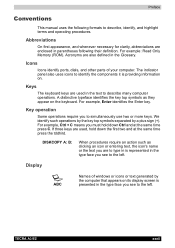
For example: Read Only Memory (ROM). A distinctive typeface identifies the key top symbols as clicking an icon or entering text, the icon's name or the text you are to type ... see to identify the components it is presented in the type face you must hold down Ctrl and at the same time press the tddhird. TECRA A3/S2 xxxii The indicator panel also uses icons to the left . We identify such operations by the key top symbols separated by the computer that...
For example: Read Only Memory (ROM). A distinctive typeface identifies the key top symbols as clicking an icon or entering text, the icon's name or the text you are to type ... see to identify the components it is presented in the type face you must hold down Ctrl and at the same time press the tddhird. TECRA A3/S2 xxxii The indicator panel also uses icons to the left . We identify such operations by the key top symbols separated by the computer that...
User Manual
Page 34
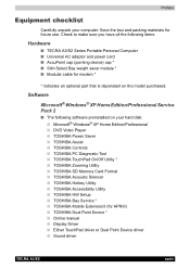
... * ■ TOSHIBA Zooming Utility ■ TOSHIBA SD Memory Card Format ■ TOSHIBA Acoustic Silencer ■ TOSHIBA Hotkey Utility ■ TOSHIBA Accessibility Utility ■ TOSHIBA HW Setup ■ TOSHIBA Bay Service * ■ TOSHIBA Mobile Extension3 (for APRIII) ■ TOSHIBA Dual Point Device * ■ Online manual ■ Display Driver ■ Either TouchPad driver or Dual Point Device driver ■ Sound driver TECRA A3/S2...
... * ■ TOSHIBA Zooming Utility ■ TOSHIBA SD Memory Card Format ■ TOSHIBA Acoustic Silencer ■ TOSHIBA Hotkey Utility ■ TOSHIBA Accessibility Utility ■ TOSHIBA HW Setup ■ TOSHIBA Bay Service * ■ TOSHIBA Mobile Extension3 (for APRIII) ■ TOSHIBA Dual Point Device * ■ Online manual ■ Display Driver ■ Either TouchPad driver or Dual Point Device driver ■ Sound driver TECRA A3/S2...


