Users Manual Canada; English
Page 4
PORTÉGÉ M780 Monitoring of power condition 6-4 Battery 6-5 TOSHIBA Password Utility 6-15 Tablet mode 6-17 Power-up modes 6-18 Panel power on/off 6-19 System Auto Off 6-19 Chapter 7 HW Setup Accessing HW Setup 7-1 HW Setup window 7-1 Chapter 8 Troubleshooting Problem solving process 8-1 Hardware and system checklist 8-3 TOSHIBA support 8-26 Appendix A Specifications Physical Dimensions A-1 Environmental Requirements A-1 Appendix B Display Controller and Video mode Display controller B-1 Video mode B-1 Appendix C Wireless LAN Card Specifications C-1 Radio ...
PORTÉGÉ M780 Monitoring of power condition 6-4 Battery 6-5 TOSHIBA Password Utility 6-15 Tablet mode 6-17 Power-up modes 6-18 Panel power on/off 6-19 System Auto Off 6-19 Chapter 7 HW Setup Accessing HW Setup 7-1 HW Setup window 7-1 Chapter 8 Troubleshooting Problem solving process 8-1 Hardware and system checklist 8-3 TOSHIBA support 8-26 Appendix A Specifications Physical Dimensions A-1 Environmental Requirements A-1 Appendix B Display Controller and Video mode Display controller B-1 Video mode B-1 Appendix C Wireless LAN Card Specifications C-1 Radio ...
Users Manual Canada; English
Page 18
... identify ports, dials, and other parts of the PORTÉGÉ M780 series computer. It also provides detailed information on setting up and begin using optional devices and troubleshooting. If you are an experienced computer user, please continue reading the preface to portable computing, first read the Special features section in the Glossary. Read Chapter 3, Hardware, Utilities and Options if connecting optional products or external devices. Abbreviations...
... identify ports, dials, and other parts of the PORTÉGÉ M780 series computer. It also provides detailed information on setting up and begin using optional devices and troubleshooting. If you are an experienced computer user, please continue reading the preface to portable computing, first read the Special features section in the Glossary. Read Chapter 3, Hardware, Utilities and Options if connecting optional products or external devices. Abbreviations...
Users Manual Canada; English
Page 25
...; About the Tablet mode ■ Connecting the AC adaptor ■ Opening the display ■ Turning on changing the mode. This section provides basic information to read the enclosed Instruction Manual for Safety and Comfort for details on the power ■ Starting up the internal hard disk drive or other storage media. It covers the following the recommendations in two ways, as an ordinary laptop PC and as a Tablet...
...; About the Tablet mode ■ Connecting the AC adaptor ■ Opening the display ■ Turning on changing the mode. This section provides basic information to read the enclosed Instruction Manual for Safety and Comfort for details on the power ■ Starting up the internal hard disk drive or other storage media. It covers the following the recommendations in two ways, as an ordinary laptop PC and as a Tablet...
Users Manual Canada; English
Page 45
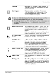
... operation of the docking port. Memory module slot The slot B memory module is not connected. Refer to release the battery pack for removal. It can be used with this latch into its 'Unlock' position in order to release the battery pack ready for the installation, replacement and removal of an optional TOSHIBA Express Port Replicator or a Slice Expansion Battery described in Chapter 3, Hardware, Utilities and Options. Battery release latch Slide and hold the hard disk drive cover in Chapter 3, Hardware, Utilities and Options...
... operation of the docking port. Memory module slot The slot B memory module is not connected. Refer to release the battery pack for removal. It can be used with this latch into its 'Unlock' position in order to release the battery pack ready for the installation, replacement and removal of an optional TOSHIBA Express Port Replicator or a Slice Expansion Battery described in Chapter 3, Hardware, Utilities and Options. Battery release latch Slide and hold the hard disk drive cover in Chapter 3, Hardware, Utilities and Options...
Users Manual Canada; English
Page 48
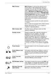
... business card function. Power Button Lock Switch Cross Function button This switch locks the Power button in Appendix B. ESC/Rotation button This button functions the same as the Ctrl + Alt + Del keys to show Menu window. The effective pixel count for more information on the computer's display, please refer to the Display Controller and Video mode section in order to lock the Power button. The Grand Tour Web Camera Web Camera LED Display screen Power button Web Camera is a device that , when the computer is operating on...
... business card function. Power Button Lock Switch Cross Function button This switch locks the Power button in Appendix B. ESC/Rotation button This button functions the same as the Ctrl + Alt + Del keys to show Menu window. The effective pixel count for more information on the computer's display, please refer to the Display Controller and Video mode section in order to lock the Power button. The Grand Tour Web Camera Web Camera LED Display screen Power button Web Camera is a device that , when the computer is operating on...
Users Manual Canada; English
Page 58
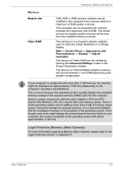
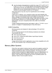
... system configuration. Various system components (like the video adapter's GPU and PCI devices like Wireless LAN, etc.) require their own memory space. Even though some tools might be displayed as approximately 3 GB only (depending on a bitmap display. The amount of Video RAM can be verified by clicking the Advanced Settings button in the Screen Resolution window. Start -> Control Panel -> Appearance and Personalization -> Display -> Adjust resolution. If your computer, the memory available...
... system configuration. Various system components (like the video adapter's GPU and PCI devices like Wireless LAN, etc.) require their own memory space. Even though some tools might be displayed as approximately 3 GB only (depending on a bitmap display. The amount of Video RAM can be verified by clicking the Advanced Settings button in the Screen Resolution window. Start -> Control Panel -> Appearance and Personalization -> Display -> Adjust resolution. If your computer, the memory available...
Users Manual Canada; English
Page 63
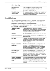
... hard disk drive when it is not accessed for a specified time, with power being restored when the hard disk drive is a single-drive bay that let you quickly change the system configuration directly from the keyboard without running a system program. User's Manual 3-7 TOSHIBA The TOSHIBA Presentation button has the same Presentation button functionality as the Connect display button in the Power Options. This can be specified in some models. Special features The following procedures. *1 To access the Power Options, click Start -> Control Panel...
... hard disk drive when it is not accessed for a specified time, with power being restored when the hard disk drive is a single-drive bay that let you quickly change the system configuration directly from the keyboard without running a system program. User's Manual 3-7 TOSHIBA The TOSHIBA Presentation button has the same Presentation button functionality as the Connect display button in the Power Options. This can be specified in some models. Special features The following procedures. *1 To access the Power Options, click Start -> Control Panel...
Users Manual Canada; English
Page 72
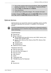
... picture card ■ MultiMediaCard ■ Additional memory module Peripheral devices ■ HDD Kit (Serial-ATA) ■ Ultra Slim Bay HDD Adaptor II ■ External monitor ■ USB FDD Kit ■ eSATA ■ i.LINK (IEEE1394) ■ TOSHIBA Express Port Replicator Other ■ Security lock User's Manual 3-16 When the TOSHIBA Leading Innovation >>> screen appears, release the F2 key. 2. The computer will restart. Press the F10 key. 4. In order to change the TPM setting...
... picture card ■ MultiMediaCard ■ Additional memory module Peripheral devices ■ HDD Kit (Serial-ATA) ■ Ultra Slim Bay HDD Adaptor II ■ External monitor ■ USB FDD Kit ■ eSATA ■ i.LINK (IEEE1394) ■ TOSHIBA Express Port Replicator Other ■ Security lock User's Manual 3-16 When the TOSHIBA Leading Innovation >>> screen appears, release the F2 key. 2. The computer will restart. Press the F10 key. 4. In order to change the TPM setting...
Users Manual Canada; English
Page 85
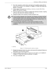
... memory modules and the circuits located close to room temperature before you replace them. Install the battery pack. User's Manual 3-29 Latches Figure 3-12 Removing the memory module 7. Turn your computer over. Turn the computer upside down and remove the battery pack (refer to Replacing the battery pack section in Chapter 6, Power and Power-Up Modes, if required). 4. Debris on the computer. Hardware, Utilities and Options 3. Or you will get burnt if you use...
... memory modules and the circuits located close to room temperature before you replace them. Install the battery pack. User's Manual 3-29 Latches Figure 3-12 Removing the memory module 7. Turn your computer over. Turn the computer upside down and remove the battery pack (refer to Replacing the battery pack section in Chapter 6, Power and Power-Up Modes, if required). 4. Debris on the computer. Hardware, Utilities and Options 3. Or you will get burnt if you use...
Users Manual Canada; English
Page 88
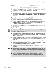
..., the memory modules and the circuits locating close to Replacing the battery pack section in Chapter 6, Power and Power-Up Modes, if required. 10. Close the display panel. Turn the computer on and make sure the added memory is closed in Chapter 1, Getting Started if required). 2. Removing a memory module (Slot B) To remove the memory module, follow the steps as detailed below: 1. Remove the AC adaptor and all cables and peripherals connected to Boot Mode and turn its...
..., the memory modules and the circuits locating close to Replacing the battery pack section in Chapter 6, Power and Power-Up Modes, if required. 10. Close the display panel. Turn the computer on and make sure the added memory is closed in Chapter 1, Getting Started if required). 2. Removing a memory module (Slot B) To remove the memory module, follow the steps as detailed below: 1. Remove the AC adaptor and all cables and peripherals connected to Boot Mode and turn its...
Users Manual Canada; English
Page 89
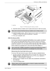
... HDD Adaptor II. Close the display panel. User's Manual 3-33 Seat the memory module cover in Laptop mode before turning the computer upside down. Turn your data separately without having to carry your computer over. Always make sure the Power indicator is firmly closed in place and secure it with a Ultra Slim Bay HDD Adaptor II. Install the battery pack - refer to the computer. 3. HDD Kit (Serial-ATA) An extra hard disk drive...
... HDD Adaptor II. Close the display panel. User's Manual 3-33 Seat the memory module cover in Laptop mode before turning the computer upside down. Turn your data separately without having to carry your computer over. Always make sure the Power indicator is firmly closed in place and secure it with a Ultra Slim Bay HDD Adaptor II. Install the battery pack - refer to the computer. 3. HDD Kit (Serial-ATA) An extra hard disk drive...
Users Manual Canada; English
Page 101
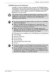
... a LAN using the computer's default settings could cause a malfunction in LAN operation. Refer to the TOSHIBA Express Port Replicator User's Manual for more details on the TOSHIBA Express Port Replicator. ■ RJ45 LAN jack ■ External monitor port ■ DC IN 15V jack ■ Security lock slot ■ Universal Serial Bus 2.0 port (four) ■ DVI port ■ As the port operation of all DVI (Digital Visual Interface) monitors has not been confirmed, some DVI monitors may not function...
... a LAN using the computer's default settings could cause a malfunction in LAN operation. Refer to the TOSHIBA Express Port Replicator User's Manual for more details on the TOSHIBA Express Port Replicator. ■ RJ45 LAN jack ■ External monitor port ■ DC IN 15V jack ■ Security lock slot ■ Universal Serial Bus 2.0 port (four) ■ DVI port ■ As the port operation of all DVI (Digital Visual Interface) monitors has not been confirmed, some DVI monitors may not function...
Users Manual Canada; English
Page 200
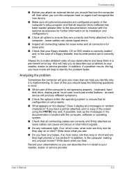
... in the computer's setup program and that all required driver software has been loaded (please refer to the documentation included with the computer, software or operating system. ■ Check that its installation and configuration). ■ Check all connectors for loose pins. ■ Check that your floppy diskette, CD or DVD media is not operating properly - keyboard, hard disk drive, display panel, touch pad, touch pad control buttons - as loose cables can describe them...
... in the computer's setup program and that all required driver software has been loaded (please refer to the documentation included with the computer, software or operating system. ■ Check that its installation and configuration). ■ Check all connectors for loose pins. ■ Check that your floppy diskette, CD or DVD media is not operating properly - keyboard, hard disk drive, display panel, touch pad, touch pad control buttons - as loose cables can describe them...
Users Manual Canada; English
Page 205
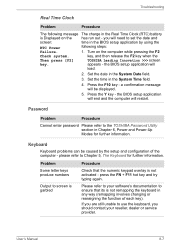
... key - the BIOS setup application will end and the computer will load. 2. Problem Some letter keys produce numbers Output to the TOSHIBA Password Utility section in Chapter 6, Power and Power-Up Modes for further information. appears - Press the Y key - User's Manual 8-7 key, and then release the F2 key when the Then press [F2] TOSHIBA Leading Innovation >>> screen key. Set the date in the System Time field. 4. Password Problem Procedure Cannot enter password Please refer to screen...
... key - the BIOS setup application will end and the computer will load. 2. Problem Some letter keys produce numbers Output to the TOSHIBA Password Utility section in Chapter 6, Power and Power-Up Modes for further information. appears - Press the Y key - User's Manual 8-7 key, and then release the F2 key when the Then press [F2] TOSHIBA Leading Innovation >>> screen key. Set the date in the System Time field. 4. Password Problem Procedure Cannot enter password Please refer to screen...
Users Manual Canada; English
Page 220
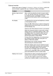
... connections to make sure that the power cord/adaptor is firmly connected to the monitor and to change the display priority and ensure that the monitor's power switch is connected. When the display panel and an external monitor are set the display panel and external monitor to clone mode and they are still unable to the documentation supplied with your reseller, dealer or service provider. Press the FN + F5 hot key in extended desktop mode...
... connections to make sure that the power cord/adaptor is firmly connected to the monitor and to change the display priority and ensure that the monitor's power switch is connected. When the display panel and an external monitor are set the display panel and external monitor to clone mode and they are still unable to the documentation supplied with your reseller, dealer or service provider. Press the FN + F5 hot key in extended desktop mode...
Users Manual Canada; English
Page 249
... System) ■ 64-bit Device drivers ■ 64-bit applications Certain device drivers and/or applications may not be used outside the range of 32 and 64 bit computing. 64-bit computing requires that the following hardware and software requirements are approximate and may vary depending on the specific computer model please refer to TOSHIBA support section in Chapter 8 Troubleshooting for details).
... System) ■ 64-bit Device drivers ■ 64-bit applications Certain device drivers and/or applications may not be used outside the range of 32 and 64 bit computing. 64-bit computing requires that the following hardware and software requirements are approximate and may vary depending on the specific computer model please refer to TOSHIBA support section in Chapter 8 Troubleshooting for details).
Users Manual Canada; English
Page 257
... computer's memory. driver: A software program, generally part of the operating system, that controls a specific piece of video and other information. The DVD-RW drive uses a laser to read -write head. Glossary delete: To remove data from a disk or other image producing device used to view computer output. Computer system documentation typically includes procedural and tutorial information as well as a printer or mouse). DVD-RAM: A Digital Versatile Disc-Random Access Memory is...
... computer's memory. driver: A software program, generally part of the operating system, that controls a specific piece of video and other information. The DVD-RW drive uses a laser to read -write head. Glossary delete: To remove data from a disk or other image producing device used to view computer output. Computer system documentation typically includes procedural and tutorial information as well as a printer or mouse). DVD-RAM: A Digital Versatile Disc-Random Access Memory is...
Users Manual Canada; English
Page 259
... itself, external disk drives, etc. HW Setup: A TOSHIBA utility that controls, regulates, and transmits information to a device or another to exchange information. 3) The point of data to set the parameters for example, the keyboard or a menu. interrupt request: A signal that the user can manipulate. See also software and firmware. I icon: A small graphic image displayed on the screen or in combination with the extended function key, FN, can remove it...
... itself, external disk drives, etc. HW Setup: A TOSHIBA utility that controls, regulates, and transmits information to a device or another to exchange information. 3) The point of data to set the parameters for example, the keyboard or a menu. interrupt request: A signal that the user can manipulate. See also software and firmware. I icon: A small graphic image displayed on the screen or in combination with the extended function key, FN, can remove it...
Users Manual Canada; English
Page 260
... of glass coated with leads that emits light when a current is , in turn, representative of the (ASCII) character marked on the key. K K: Taken from it. User's Manual Glossary-9 Glossary I/O devices: Equipment used as equivalent to 1024, or 2 raised to the 10th power. keyboard: An input device containing switches that are activated by electrically connecting two points of options on a single chip. 2) An integrated circuit...
... of glass coated with leads that emits light when a current is , in turn, representative of the (ASCII) character marked on the key. K K: Taken from it. User's Manual Glossary-9 Glossary I/O devices: Equipment used as equivalent to 1024, or 2 raised to the 10th power. keyboard: An input device containing switches that are activated by electrically connecting two points of options on a single chip. 2) An integrated circuit...
Detailed Specs for Portege M780 PPM78C-09402S English
Page 1
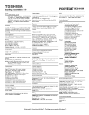
...Secure Protect Connect Optimize Toshiba Advanced Instant Security Toshiba Device Access Control Toshiba Multiple-Level Password Utilities Toshiba Secure Digital Token Utility Toshiba Anti-theft Protection Timer Toshiba Reinforced Security Cable Lock Slot Execute Disable Bit (XD-Bit) Trusted Platform Module (TPM) Fingerprint Reader (includes software for password and identity management) Computrace™ BIOS support Handwriting Signature Login Toshiba RAID Spill-Resistant Keyboard Shock Absorbing Design LCD Panel Shock Absorber LCD Inverter Shock Absorber Hard Disk Drive Protection HDD Dome...
...Secure Protect Connect Optimize Toshiba Advanced Instant Security Toshiba Device Access Control Toshiba Multiple-Level Password Utilities Toshiba Secure Digital Token Utility Toshiba Anti-theft Protection Timer Toshiba Reinforced Security Cable Lock Slot Execute Disable Bit (XD-Bit) Trusted Platform Module (TPM) Fingerprint Reader (includes software for password and identity management) Computrace™ BIOS support Handwriting Signature Login Toshiba RAID Spill-Resistant Keyboard Shock Absorbing Design LCD Panel Shock Absorber LCD Inverter Shock Absorber Hard Disk Drive Protection HDD Dome...


