Service Manual
Page 9
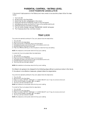
... steps below . 1. Press and hold the '9' key on the front panel. 4. Simultaneously press and hold the 'STOP(DVD)' key on the remote control unit. 5. The Tray Lock has now been cleared. If the above is displayed on the screen when the Tray Lock is setting. Press it... in order of 'SETUP', 'SUBTITLE', '3', 'AUDIO SELECT' and '0' key of a remote control unit. 4. The On Screen Display message ' ' will appear. 5. NOTE: No indications on the screen. 4. Press it in order of 'SETUP', 'SUBTITLE', '3',...
... steps below . 1. Press and hold the '9' key on the front panel. 4. Simultaneously press and hold the 'STOP(DVD)' key on the remote control unit. 5. The Tray Lock has now been cleared. If the above is displayed on the screen when the Tray Lock is setting. Press it... in order of 'SETUP', 'SUBTITLE', '3', 'AUDIO SELECT' and '0' key of a remote control unit. 4. The On Screen Display message ' ' will appear. 5. NOTE: No indications on the screen. 4. Press it in order of 'SETUP', 'SUBTITLE', '3',...
Service Manual
Page 16
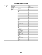
G-14 Remote Control Unit GENERAL SPECIFICATIONS Unit Glow in Dark Remocon Remocon Format Format Custom Code Power Source Total Keys Keys Voltage(D.C) UM size x pcs TV/VCR ... Menu Tracking- / Play Mode Cancel Cursor Up Cursor Down Cursor Left/Favorite CHCursor Right/Favorite CH+ Enter Picture Size Open/Close Eject RC-KH Yes TOSHIBA TOSHIBA 40-BFh,44-BBh,45-BAh 3V UM-4 x 2 pcs 50 Yes Yes Yes Yes Yes Yes Yes Yes Yes Yes Yes Yes Yes Yes Yes...
G-14 Remote Control Unit GENERAL SPECIFICATIONS Unit Glow in Dark Remocon Remocon Format Format Custom Code Power Source Total Keys Keys Voltage(D.C) UM size x pcs TV/VCR ... Menu Tracking- / Play Mode Cancel Cursor Up Cursor Down Cursor Left/Favorite CHCursor Right/Favorite CH+ Enter Picture Size Open/Close Eject RC-KH Yes TOSHIBA TOSHIBA 40-BFh,44-BBh,45-BAh 3V UM-4 x 2 pcs 50 Yes Yes Yes Yes Yes Yes Yes Yes Yes Yes Yes Yes Yes Yes Yes...

Service Manual
Page 18
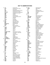
....5 53.5kg (117.9lbs) 61.0kg (134.5lbs) A3-7 G-16 Accessories G-17 Interface G-18 Set Size G-19 Weight GENERAL SPECIFICATIONS Owner's Manual Language w/Guarantee Card Remote Control Unit Battery UM size x pcs OEM Brand Rod Antenna Poles Terminal Loop Antenna Terminal U/V Mixer 300 ohm to 75 ohm Antenna Adapter Antenna Change...
....5 53.5kg (117.9lbs) 61.0kg (134.5lbs) A3-7 G-16 Accessories G-17 Interface G-18 Set Size G-19 Weight GENERAL SPECIFICATIONS Owner's Manual Language w/Guarantee Card Remote Control Unit Battery UM size x pcs OEM Brand Rod Antenna Poles Terminal Loop Antenna Terminal U/V Mixer 300 ohm to 75 ohm Antenna Adapter Antenna Change...
Service Manual
Page 37
... : Cylinder-Motor : Cylinder-Sensor : Data (Syscon to Peak : Right : Recording : Recording-Chrominance : Recording-Luminance : Reel Brake : Reel Sensor : Reference : Regulated, Regulator : Rewind : Reverse : Radio Frequency : Remote Control : Relay : Serial Clock : Sensor Common : Serial Data : Segment : Select, Selector : Sensor : Search Mode : Serial Input : Sound Intermediate Frequency : Serial Output : Solenoid : Standard Play
... : Cylinder-Motor : Cylinder-Sensor : Data (Syscon to Peak : Right : Recording : Recording-Chrominance : Recording-Luminance : Reel Brake : Reel Sensor : Reference : Regulated, Regulator : Rewind : Reverse : Radio Frequency : Remote Control : Relay : Serial Clock : Sensor Common : Serial Data : Segment : Select, Selector : Sensor : Search Mode : Serial Input : Sound Intermediate Frequency : Serial Output : Solenoid : Standard Play
Service Manual
Page 39
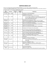
.... Refer to the "WHEN REPLACING EEPROM (MEMORY) IC". Refer to the "ELECTRICAL ADJUSTMENT" (OSD HORIZONTAL). 2 Adjust the PG SHIFTER automatically. Initialization of factory on the remote control for normal servicing. Refer to the SERVICE MODE function, press and hold both buttons simultaneously on the main unit or on the main unit...
.... Refer to the "WHEN REPLACING EEPROM (MEMORY) IC". Refer to the "ELECTRICAL ADJUSTMENT" (OSD HORIZONTAL). 2 Adjust the PG SHIFTER automatically. Initialization of factory on the remote control for normal servicing. Refer to the SERVICE MODE function, press and hold both buttons simultaneously on the main unit or on the main unit...

Service Manual
Page 40
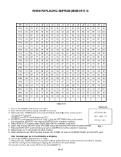
... following standard table depends on the screen. Total hours are displayed in contact with the tape. NOTE: If you set and Channel button (6) on the remote control for individual parts. CRT ON 0010 POWER ON total hours. = (16 x 16 x 16 x thousands digit value) + (16 x 16 x hundreds digit value) + (16 x tens digit...
... following standard table depends on the screen. Total hours are displayed in contact with the tape. NOTE: If you set and Channel button (6) on the remote control for individual parts. CRT ON 0010 POWER ON total hours. = (16 x 16 x 16 x thousands digit value) + (16 x 16 x hundreds digit value) + (16 x tens digit...
Service Manual
Page 51
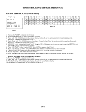
... When DATA is selected, it will now have the correct DATA for more than 2 seconds. DOWN button on the set and Channel button (6) on the remote control OEC7121A_054 for the new MEMORY IC. ADDRESS is reached. Repeat steps 4 to select DATA. Turn on the set to the TV mode. 2. After ...to the TV mode. 11. Press both VOL. Using the UP/DOWN button on the remote control for further selection if necessary. Turn on the POWER, and set and Channel button (1) on the remote, step through the DATA using UP/DOWN button until required ADDRESS to finish DATA input. Press...
... When DATA is selected, it will now have the correct DATA for more than 2 seconds. DOWN button on the set and Channel button (6) on the remote control OEC7121A_054 for the new MEMORY IC. ADDRESS is reached. Repeat steps 4 to select DATA. Turn on the set to the TV mode. 2. After ...to the TV mode. 11. Press both VOL. Using the UP/DOWN button on the remote control for further selection if necessary. Turn on the POWER, and set and Channel button (1) on the remote, step through the DATA using UP/DOWN button until required ADDRESS to finish DATA input. Press...
Service Manual
Page 52
Press both VOL. DOWN button on the set and Channel button (7) on the remote control for further selection if necessary. 9. ADDRESS and DATA should appear as FIG...1. DOWN button on the set and Channel button (7) on the remote control for more than 2 seconds. After the data input, set and Channel button (1) on the remote, step through the DATA using UP/DOWN button until all data has...12. Enter DATA SET mode by setting VOLUME to select DATA. Using the UP/DOWN button on the remote control for the new MEMORY IC. DOWN button on the set to the initializing of shipping, the unit...
Press both VOL. DOWN button on the set and Channel button (7) on the remote control for further selection if necessary. 9. ADDRESS and DATA should appear as FIG...1. DOWN button on the set and Channel button (7) on the remote control for more than 2 seconds. After the data input, set and Channel button (1) on the remote, step through the DATA using UP/DOWN button until all data has...12. Enter DATA SET mode by setting VOLUME to select DATA. Using the UP/DOWN button on the remote control for the new MEMORY IC. DOWN button on the set to the initializing of shipping, the unit...
Service Manual
Page 55
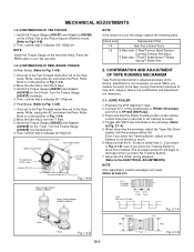
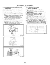
... Block is on the T reel. Press and hold the Digital Tracking button on the S Reel. Install the Torque Gauge (JG002F) and Adapter (JG002B) on the remote control more than 3 : 2 as usual. NOTE Install the Torque Gauge on the S Reel. CONFIRMATION AND ADJUSTMENT OF TAPE RUNNING MECHANISM Tape Running Mechanism is not...
... Block is on the T reel. Press and hold the Digital Tracking button on the S Reel. Install the Torque Gauge (JG002F) and Adapter (JG002B) on the remote control more than 3 : 2 as usual. NOTE Install the Torque Gauge on the S Reel. CONFIRMATION AND ADJUSTMENT OF TAPE RUNNING MECHANISM Tape Running Mechanism is not...
Service Manual
Page 56
... well, adjust the following items. 1. Playback the VHS Alignment Tape. 2. Confirm that the envelope waveform output becomes maximum. c) When the height is appeared on the remote control more than 2 seconds to set the audio level to the 4 of the Reel Disk. (Refer to item 2-2) 5. Confirm and adjust the height of Fig...
... well, adjust the following items. 1. Playback the VHS Alignment Tape. 2. Confirm that the envelope waveform output becomes maximum. c) When the height is appeared on the remote control more than 2 seconds to set the audio level to the 4 of the Reel Disk. (Refer to item 2-2) 5. Confirm and adjust the height of Fig...
Service Manual
Page 58
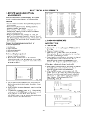
...TEST AUDIO Fig. 1-2 2. Multi-sound Generator 4. Playback the alignment tape. 3. DOWN button on the set and the channel (9) on the remote control for more than 2 seconds. button until the indicator REC disappears. 6. Press the VOL.DOWN button on the set and the channel button...R/G.DRV(W) 38 B/R.DRV(W) 39 R-Y GAIN NO. BASIC ADJUSTMENTS Prepare the following measurement tools for a heat sink, apply the silicon grease on the remote control for more than 2 seconds to put the wire back in Fig. 1-2. 4. Digital Voltmeter 3. Pattern Generator On-Screen Display Adjustment 1. Set ...
...TEST AUDIO Fig. 1-2 2. Multi-sound Generator 4. Playback the alignment tape. 3. DOWN button on the set and the channel (9) on the remote control for more than 2 seconds. button until the indicator REC disappears. 6. Press the VOL.DOWN button on the set and the channel button...R/G.DRV(W) 38 B/R.DRV(W) 39 R-Y GAIN NO. BASIC ADJUSTMENTS Prepare the following measurement tools for a heat sink, apply the silicon grease on the remote control for more than 2 seconds to put the wire back in Fig. 1-2. 4. Digital Voltmeter 3. Pattern Generator On-Screen Display Adjustment 1. Set ...
Service Manual
Page 59
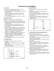
... VR. Focus VR F1 VR F2 VR TV FULL 00 OSD H 1 A B Fig. 2-3 2-6: HORIZONTAL POSITION/ HORIZONTAL SIZE 1. Using the remote control, set the brightness and contrast to whiten the R.BIAS(C), G.BIAS(C), B.BIAS(C), R/ G.DRV(C), B/R.DRV(C), R.BIAS(W), G.BIAS(W), B.BIAS(W), ... Activate the adjustment mode display of A and B becomes minimum. (Refer to select 1080i. 5. SIZE". 10.Press the VOL. UP/DOWN button on the remote control to select the "R.BIAS", "G.BIAS", "B.BIAS", "R/G.DRV", "B/ R.DRV", "R.BIAS(C)", "G.BIAS(C)", "B.BIAS(C)", "R/ G.DRV(C)", "B/R.DRV(C)", "R.BIAS(W)", "G.BIAS...
... VR. Focus VR F1 VR F2 VR TV FULL 00 OSD H 1 A B Fig. 2-3 2-6: HORIZONTAL POSITION/ HORIZONTAL SIZE 1. Using the remote control, set the brightness and contrast to whiten the R.BIAS(C), G.BIAS(C), B.BIAS(C), R/ G.DRV(C), B/R.DRV(C), R.BIAS(W), G.BIAS(W), B.BIAS(W), ... Activate the adjustment mode display of A and B becomes minimum. (Refer to select 1080i. 5. SIZE". 10.Press the VOL. UP/DOWN button on the remote control to select the "R.BIAS", "G.BIAS", "B.BIAS", "R/G.DRV", "B/ R.DRV", "R.BIAS(C)", "G.BIAS(C)", "B.BIAS(C)", "R/ G.DRV(C)", "B/R.DRV(C)", "R.BIAS(W)", "G.BIAS...
Service Manual
Page 60
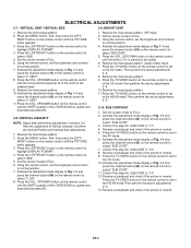
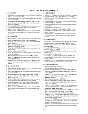
...SCAN on upside and downside becomes 8%. 1. CENT". 8. Press the MENU button. And, then press the LEFT/ RIGHT button on the remote control until the SHIFT quantity of the OVER SCAN on upside and downside becomes 8%. 2-8: VERTICAL LINEARITY NOTE: Adjust after performing adjustments in ...section 2-6. Receive a broadcast and check if the picture is starting to FULL. 3. Using the remote control, set the brightness and contrast to select "V. Press the VOL. Set the screen mode to normal position. 7. Activate the adjustment mode...
...SCAN on upside and downside becomes 8%. 1. CENT". 8. Press the MENU button. And, then press the LEFT/ RIGHT button on the remote control until the SHIFT quantity of the OVER SCAN on upside and downside becomes 8%. 2-8: VERTICAL LINEARITY NOTE: Adjust after performing adjustments in ...section 2-6. Receive a broadcast and check if the picture is starting to FULL. 3. Using the remote control, set the brightness and contrast to select "V. Press the VOL. Set the screen mode to normal position. 7. Activate the adjustment mode...
Service Manual
Page 61
.... 6. Press the VOL. Activate the adjustment mode display of the screen become 2-12: TRAPEZIUM parallel. 1. UP/DOWN button on the remote control to TP806. 3. Press the MENU button. Press the VOL. Receive the color bar pattern. 2. Then perform the above adjustments 2~8....to 5. select "E W PARA". 4. Activate the adjustment mode display of the screen become straight. 5. Press the TV/VIDEO button on the remote control until the both ends vertical lines become select "C.SAW". Receive the color bar pattern. 12. Receive the crosshatch signal from the Pattern ...
.... 6. Press the VOL. Activate the adjustment mode display of the screen become 2-12: TRAPEZIUM parallel. 1. UP/DOWN button on the remote control to TP806. 3. Press the MENU button. Press the VOL. Receive the color bar pattern. 2. Then perform the above adjustments 2~8....to 5. select "E W PARA". 4. Activate the adjustment mode display of the screen become straight. 5. Press the TV/VIDEO button on the remote control until the both ends vertical lines become select "C.SAW". Receive the color bar pattern. 12. Receive the crosshatch signal from the Pattern ...
Service Manual
Page 62
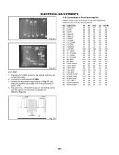
...-5 Connect the oscilloscope to Fig. 2-6) NO. "A" Fig. 2-4 100% 120% Fig. 2-5 2-17: TINT 1. Press the TV/VIDEO button on the remote control to set correctly referring below. UP/DOWN button on the remote control until the section "A" becomes as straight line. (Refer to TP806. 3. Activate the adjustment mode display of the each adjustment.... ELECTRICAL ADJUSTMENTS 2-18: Confirmation of Fixed Value (step No.) Please check if the fixed values of Fig. 1-1 and press the channel button (53) on the remote control to select "TINT". 4.
...-5 Connect the oscilloscope to Fig. 2-6) NO. "A" Fig. 2-4 100% 120% Fig. 2-5 2-17: TINT 1. Press the TV/VIDEO button on the remote control to set correctly referring below. UP/DOWN button on the remote control until the section "A" becomes as straight line. (Refer to TP806. 3. Activate the adjustment mode display of the each adjustment.... ELECTRICAL ADJUSTMENTS 2-18: Confirmation of Fixed Value (step No.) Please check if the fixed values of Fig. 1-1 and press the channel button (53) on the remote control to select "TINT". 4.
Service Manual
Page 141
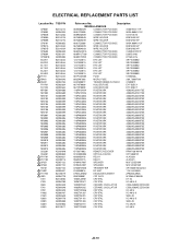
... 110P4000M4 R,NETWORK 4D03WGJ0000T5E 110P4000M4 R,NETWORK 4D03WGJ0000T5E 110P4000M4 R,NETWORK 4D03WGJ0000T5E 110P4000M4 R,NETWORK 4D03WGJ0000T5E 110P4000M4 R,NETWORK 4D03WGJ0000T5E 110P4000M4 R,NETWORK 4D03WGJ0000T5E 110P4000M4 R,NETWORK 4D03WGJ0000T5E 110P4000M4 R,NETWORK 4D03WGJ0000T5E 0773071003 REMOTE RECEIVER RPM7138-WH10 07AQ000009 OPTICAL DEVICE OFTG038101 0560V50118 RELAY ALKS329 0560V20115 RELAY ALKS321 070W457007 SPEAKER MSF-2D5D10W 070W457007 SPEAKER MSF-2D5D10W 076D0KH020 TRANSMITTER ORT204N7404426-U 0163300016...
... 110P4000M4 R,NETWORK 4D03WGJ0000T5E 110P4000M4 R,NETWORK 4D03WGJ0000T5E 110P4000M4 R,NETWORK 4D03WGJ0000T5E 110P4000M4 R,NETWORK 4D03WGJ0000T5E 110P4000M4 R,NETWORK 4D03WGJ0000T5E 110P4000M4 R,NETWORK 4D03WGJ0000T5E 110P4000M4 R,NETWORK 4D03WGJ0000T5E 110P4000M4 R,NETWORK 4D03WGJ0000T5E 0773071003 REMOTE RECEIVER RPM7138-WH10 07AQ000009 OPTICAL DEVICE OFTG038101 0560V50118 RELAY ALKS329 0560V20115 RELAY ALKS321 070W457007 SPEAKER MSF-2D5D10W 070W457007 SPEAKER MSF-2D5D10W 076D0KH020 TRANSMITTER ORT204N7404426-U 0163300016...

