Installation Manual
Page 4
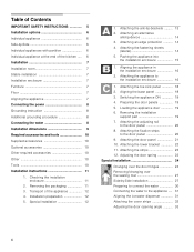
... 1. Table of Contents IMPORTANT SAFETY INSTRUCTIONS 5 Installation options 6 Individual appliance 6 Side-by -Side installation 27 Preparing to connect the water 30 Connecting the water to the door panel 20 8. Removing the packaging 11 3. Transport of the kitchen ..... 6 Installation 7 Installation room 7 Stable installation 7 Installation enclosure 7 Furniture 7 Floor 7 Aligning the appliance 7 Connecting the power 8 Grounding instruction 8 Additional grounding procedure 8 Connecting the water 8 Installation dimensions 9 Required accessories and tools 10 Supplied...
... 1. Table of Contents IMPORTANT SAFETY INSTRUCTIONS 5 Installation options 6 Individual appliance 6 Side-by -Side installation 27 Preparing to connect the water 30 Connecting the water to the door panel 20 8. Removing the packaging 11 3. Transport of the kitchen ..... 6 Installation 7 Installation room 7 Stable installation 7 Installation enclosure 7 Furniture 7 Floor 7 Aligning the appliance 7 Connecting the power 8 Grounding instruction 8 Additional grounding procedure 8 Connecting the water 8 Installation dimensions 9 Required accessories and tools 10 Supplied...
Installation Manual
Page 5
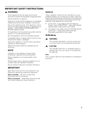
... Owner's Manual for use . Be sure to prevent the possibility of this warning. General These installation instructions are top-heavy and must be made by a qualified service technician. In the absence of this appliance only for water, electrical power and grounding must comply with the Canadian Electric Code C22.1 - latest edition/Provincial and Municipal codes and/or local codes. Keep doors closed until the appliance is required. Repairs...
... Owner's Manual for use . Be sure to prevent the possibility of this warning. General These installation instructions are top-heavy and must be made by a qualified service technician. In the absence of this appliance only for water, electrical power and grounding must comply with the Canadian Electric Code C22.1 - latest edition/Provincial and Municipal codes and/or local codes. Keep doors closed until the appliance is required. Repairs...

Installation Manual
Page 6
...". These are opened at the end of the kitchen If one side of the side panel are many different installation options. See the section on "Required accessories and tools/Optional accessories". Minimum thickness of the kitchen. Individual appliance at the same time. Use the Heater Kit for model 4, note the thickness of the door panels to the...
...". These are opened at the end of the kitchen If one side of the side panel are many different installation options. See the section on "Required accessories and tools/Optional accessories". Minimum thickness of the kitchen. Individual appliance at the same time. Use the Heater Kit for model 4, note the thickness of the door panels to the...
Installation Manual
Page 7
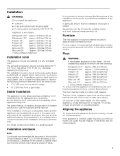
..., make sure that the installation enclosure is strongly recommended the top panel of the niche be of the appliance. Do not open the door until there is installed securely and functions properly, the floor must be flat and level. It is always a firm connection between the installation enclosure and back wall! A prerequisite for a trouble-free installation of solid material at least 4" deep...
..., make sure that the installation enclosure is strongly recommended the top panel of the niche be of the appliance. Do not open the door until there is installed securely and functions properly, the floor must be flat and level. It is always a firm connection between the installation enclosure and back wall! A prerequisite for a trouble-free installation of solid material at least 4" deep...
Installation Manual
Page 8
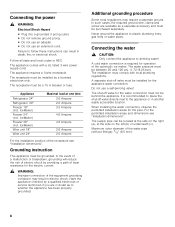
... listed 3 wire power supply cord. In the event of a malfunction or breakdown, grounding will reduce the risk of electric shock by a licensed electrician only. The installation must be behind the appliance. Do not use an extension cord. The shut-off valve for operation of the equipment grounding conductor may require a seperate ground. For the permitted installation areas and dimensions see "Installation dimensions". The appliance requires a 3-wire receptacle. A cold water...
... listed 3 wire power supply cord. In the event of a malfunction or breakdown, grounding will reduce the risk of electric shock by a licensed electrician only. The installation must be behind the appliance. Do not use an extension cord. The shut-off valve for operation of the equipment grounding conductor may require a seperate ground. For the permitted installation areas and dimensions see "Installation dimensions". The appliance requires a 3-wire receptacle. A cold water...
Installation Manual
Page 10
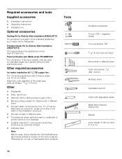
... 5/16" (8 mm) hex nut driver Wood drills in different sizes Thin plywood sheet, particle board or cardboard to Refrigerator. protective sheets) Adhesive tape Note: Before using, check whether the removed adhesive tape leaves adhesive residue on high-quality work . Required accessories and tools Supplied accessories Installation instructions Operating instructions Installation kit Optional accessories Sealing Kit for Side-by -Side Installation XHEATKIT10 If the gap...
... 5/16" (8 mm) hex nut driver Wood drills in different sizes Thin plywood sheet, particle board or cardboard to Refrigerator. protective sheets) Adhesive tape Note: Before using, check whether the removed adhesive tape leaves adhesive residue on high-quality work . Required accessories and tools Supplied accessories Installation instructions Operating instructions Installation kit Optional accessories Sealing Kit for Side-by -Side Installation XHEATKIT10 If the gap...
Installation Manual
Page 11
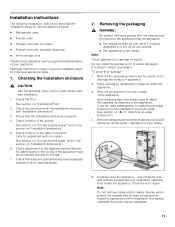
... was used subsequently for appliances with ice-water dispenser Wine storage units Therefore the diagrams may be damaged. 11 All cabinet parts in the vicinity of the appliance must be careful not to special installation steps for various appliance types: Refrigerator units Freezer units Freezer units with ice maker Freezer units with ice maker). Removing the packaging , WARNING: Be careful, otherwise people who are opened. ...
... was used subsequently for appliances with ice-water dispenser Wine storage units Therefore the diagrams may be damaged. 11 All cabinet parts in the vicinity of the appliance must be careful not to special installation steps for various appliance types: Refrigerator units Freezer units Freezer units with ice maker Freezer units with ice maker). Removing the packaging , WARNING: Be careful, otherwise people who are opened. ...
Installation Manual
Page 12
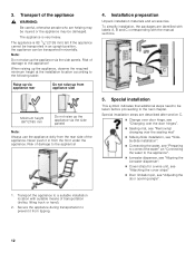
Transport of the appliance , WARNING: Be careful, otherwise people who are described after section C. Change over door hinge, see "Changing over the door hinges". Sealing mat, see "Removing/ changing over the sealing mat" Side-by-Side installation, see "Sideby-Side installation". Connecting the water, see "Preparing to connect the water" an "Connecting the water to prevent it in an upright position, the appliance can be...
Transport of the appliance , WARNING: Be careful, otherwise people who are described after section C. Change over door hinge, see "Changing over the door hinges". Sealing mat, see "Removing/ changing over the sealing mat" Side-by-Side installation, see "Sideby-Side installation". Connecting the water, see "Preparing to connect the water" an "Connecting the water to prevent it in an upright position, the appliance can be...

Installation Manual
Page 13
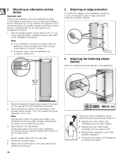
... on "Installation dimensions". 2. Always wear safety glasses and other necessary protective devices or apparel when installing or working with dowels and screws: Not recommended for use in new concrete which the screws could penetrate. , CAUTION: Risk of the anti-tip-brackets according to secure the appliance. Note: 2 anti-tip-brackets are no electrical wires or plumbing...
... on "Installation dimensions". 2. Always wear safety glasses and other necessary protective devices or apparel when installing or working with dowels and screws: Not recommended for use in new concrete which the screws could penetrate. , CAUTION: Risk of the anti-tip-brackets according to secure the appliance. Note: 2 anti-tip-brackets are no electrical wires or plumbing...
Installation Manual
Page 14
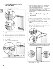
... to connect the water". Attaching an edge protection To protect the edges of the installation enclosure. 14 These are provided after section C. Change over door hinge, see "Changing over the door hinges". Sealing mat, see "Removing/ changing over the sealing mat" Side-by at least 2" (50.8 mm). 3. Attaching the fastening sheets (lateral) Attach the fastening sheets (lateral) to the required length. Predrill the...
... to connect the water". Attaching an edge protection To protect the edges of the installation enclosure. 14 These are provided after section C. Change over door hinge, see "Changing over the door hinges". Sealing mat, see "Removing/ changing over the sealing mat" Side-by at least 2" (50.8 mm). 3. Attaching the fastening sheets (lateral) Attach the fastening sheets (lateral) to the required length. Predrill the...
Installation Manual
Page 15
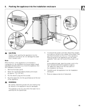
5. Do not damage the water line or power cord. Note: When the floor or the appliance is pushing into the guard tube. 5. Carefully push the appliance into the socket. 4. To prevent the power cord from the rear panel of the appliance. Put the electric plug into the installation enclosure. 7. Remove the base panel. 2. or Using adhesive tape, tape the power cord to the floor centrally behind the...
5. Do not damage the water line or power cord. Note: When the floor or the appliance is pushing into the guard tube. 5. Carefully push the appliance into the socket. 4. To prevent the power cord from the rear panel of the appliance. Put the electric plug into the installation enclosure. 7. Remove the base panel. 2. or Using adhesive tape, tape the power cord to the floor centrally behind the...
Installation Manual
Page 16
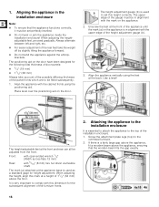
... appliance to set perfectly levelled. Do not twist or jam the appliance inside the installation enclosure! The positioning aid on the appliance is used to the installation enclosure It is a fairly large gap above the appliance, fit a wooden beam above the floor. When adjusting the height, align this dimension for height adjustment. Align the appliance vertically using the positioning...
... appliance to set perfectly levelled. Do not twist or jam the appliance inside the installation enclosure! The positioning aid on the appliance is used to the installation enclosure It is a fairly large gap above the appliance, fit a wooden beam above the floor. When adjusting the height, align this dimension for height adjustment. Align the appliance vertically using the positioning...
Installation Manual
Page 17
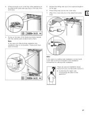
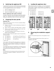
...-by -side installation. Instructions are special installation steps. These parts have been removed. Shorten the fitting strip (a) to the required height to the appliance". 17 Attach the cover strip (b) to them. Screw on the top of the appliance fix the attachment plate side lugs (top) to the side of the fastening sheets (lateral) with the cabinet parts located next to...
...-by -side installation. Instructions are special installation steps. These parts have been removed. Shorten the fitting strip (a) to the required height to the appliance". 17 Attach the cover strip (b) to them. Screw on the top of the appliance fix the attachment plate side lugs (top) to the side of the fastening sheets (lateral) with the cabinet parts located next to...
Installation Manual
Page 19
... from customer service as possible. The total weight of the door panel must be attached instead of the overall kitchen front later on "Required accessories and tools/Optional accessories". Removing the installation support part Unscrew the positioning aid from damage possibly caused to the water pipe feeding the appliance, keep the shut-off . Press the POWER button again to a metal strip on the door panels, always...
... from customer service as possible. The total weight of the door panel must be attached instead of the overall kitchen front later on "Required accessories and tools/Optional accessories". Removing the installation support part Unscrew the positioning aid from damage possibly caused to the water pipe feeding the appliance, keep the shut-off . Press the POWER button again to a metal strip on the door panels, always...
Installation Manual
Page 20
... (a) and remove the adjusting rail (b). 3. Remove the door panel. 20 Determine and mark the centerline of the gap continuously. Attaching the fixation strips to the door panel 1. Align the door panel with the next installation step ("C / 9. One screw should be inserted under each double threaded bolt. The adjusting rail features a variety of holes for stainless steel doors. Screw on the adjusting rail and...
... (a) and remove the adjusting rail (b). 3. Remove the door panel. 20 Determine and mark the centerline of the gap continuously. Attaching the fixation strips to the door panel 1. Align the door panel with the next installation step ("C / 9. One screw should be inserted under each double threaded bolt. The adjusting rail features a variety of holes for stainless steel doors. Screw on the adjusting rail and...
Installation Manual
Page 22
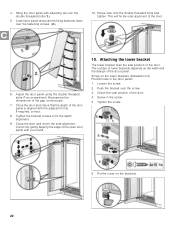
... Hang the door panel with the adjacent fronts. Adjust the door panel using the double threaded bolts (Torx screwdriver). The number of lower brackets depends on the width and the design of the gap continuously. 7. Check the side position of the open door panel with your hand. 10. 4. Lower door panel and push the fixing brackets down over the screw. 3. If required, correct. 8. Correct...
... Hang the door panel with the adjacent fronts. Adjust the door panel using the double threaded bolts (Torx screwdriver). The number of lower brackets depends on the width and the design of the gap continuously. 7. Check the side position of the open door panel with your hand. 10. 4. Lower door panel and push the fixing brackets down over the screw. 3. If required, correct. 8. Correct...
Installation Manual
Page 24
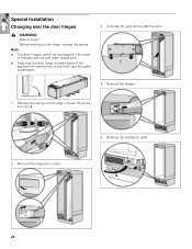
Before working on the back (put the pallet underneath). 3. Note: The door hinges cannot be exchanged in the case of injury! Remove the ventilation grille. 24 Loosen the screw from I to 0. 2. Unscrew (1.) and remove (2.) the door. 4. Remove the hinge box covers. 5. Remove the hinges. 1. Release the spring on the hinge. Special installation Changing over the door hinges , WARNING: Risk of freezers with ice and water dispensers. Switching the door hinge is made easier if the appliance is stored here on the hinge, release the spring.
Before working on the back (put the pallet underneath). 3. Note: The door hinges cannot be exchanged in the case of injury! Remove the ventilation grille. 24 Loosen the screw from I to 0. 2. Unscrew (1.) and remove (2.) the door. 4. Remove the hinge box covers. 5. Remove the hinges. 1. Release the spring on the hinge. Special installation Changing over the door hinges , WARNING: Risk of freezers with ice and water dispensers. Switching the door hinge is made easier if the appliance is stored here on the hinge, release the spring.
Installation Manual
Page 27
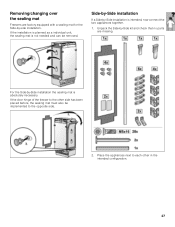
... kit and check that no parts are factory equipped with a sealing mat for the Side-by-side installation. Place the appliances next to each other side has been placed before, the sealing mat must also be removed. Side-by-Side installation If a Side-by -Side installation the sealing mat... together. 1. For the Side-by -Side installation is absolutely necessary. If the door hinge of the freezer to the opposite side. 2. Removing/changing over the sealing mat Freezers are missing. If the installation is planned as a individual unit, the sealing mat is not needed and can be implemented to...
... kit and check that no parts are factory equipped with a sealing mat for the Side-by-side installation. Place the appliances next to each other side has been placed before, the sealing mat must also be removed. Side-by-Side installation If a Side-by -Side installation the sealing mat... together. 1. For the Side-by -Side installation is absolutely necessary. If the door hinge of the freezer to the opposite side. 2. Removing/changing over the sealing mat Freezers are missing. If the installation is planned as a individual unit, the sealing mat is not needed and can be implemented to...
Installation Manual
Page 30
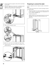
...indicated dimensions to prevent damage to prevent damage caused by -Side kit. 30 14. Preparing to connect the water (only for appliances which require a water connection) Note: Turn off valve according to the attachment plate (top): 17. Remove the installation aids. Connect both cover rails to push the bar in the appliance. 16. Install the water...to the instructions supplied by the manufacturer of the ice maker installation kit. 2. Use a tool to the bolt included in the Side-by leaking water. 1. Attach the water line to the shut-off the main water tap to the water line when...
...indicated dimensions to prevent damage to prevent damage caused by -Side kit. 30 14. Preparing to connect the water (only for appliances which require a water connection) Note: Turn off valve according to the attachment plate (top): 17. Remove the installation aids. Connect both cover rails to push the bar in the appliance. 16. Install the water...to the instructions supplied by the manufacturer of the ice maker installation kit. 2. Use a tool to the bolt included in the Side-by leaking water. 1. Attach the water line to the shut-off the main water tap to the water line when...

Installation Manual
Page 31
... on the shut-off valve and main water tap. 8. Remove the cap from the door panel (2.). 4. Push back the water line into the guard tube as far as possible (4.). Slide cover frame onto the ice-water dispenser and press in order to obtain an optimum overall appearance. Check the connection on the union nut (3.). Tighten hand-tight. 5. Using the open-ended wrench...
... on the shut-off valve and main water tap. 8. Remove the cap from the door panel (2.). 4. Push back the water line into the guard tube as far as possible (4.). Slide cover frame onto the ice-water dispenser and press in order to obtain an optimum overall appearance. Check the connection on the union nut (3.). Tighten hand-tight. 5. Using the open-ended wrench...


