Operating Instructions
Page 4
...12 Rear/Right Side/Bottom 12 Control Panel 13 Connector Panel 14 Remote Commander 15 Presentation Tool 17 Setting Up and Projecting Installing the Projector 19 Connecting the Projector 20 Connecting with a Computer ..... 20 Connecting with a VCR 22 Projecting 23 Turning Off the Power 25 Convenient Function Selecting the ... The SET SETTING Menu 36 The MENU SETTING Menu ...........38 The INSTALL SETTING Menu ......39 The INFORMATION Menu 40 Maintenance Maintenance 41 Replacing the Lamp 41 Cleaning the Air Filter 43 Troubleshooting 44 Warning Messages 47 Caution Messages 48 4 GB
...12 Rear/Right Side/Bottom 12 Control Panel 13 Connector Panel 14 Remote Commander 15 Presentation Tool 17 Setting Up and Projecting Installing the Projector 19 Connecting the Projector 20 Connecting with a Computer ..... 20 Connecting with a VCR 22 Projecting 23 Turning Off the Power 25 Convenient Function Selecting the ... The SET SETTING Menu 36 The MENU SETTING Menu ...........38 The INSTALL SETTING Menu ......39 The INFORMATION Menu 40 Maintenance Maintenance 41 Replacing the Lamp 41 Cleaning the Air Filter 43 Troubleshooting 44 Warning Messages 47 Caution Messages 48 4 GB
Operating Instructions
Page 41
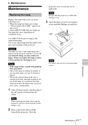
...-C190 Projector Lamp as the replacement lamp. Use of any other lamps than the LMP-C190 may scatter, causing injury. 1 Turn off the projector with a new one in the following case. • When the lamp has burnt out or dims • "Please replace the LAMP." Notes • If the lamp breaks, consult with qualified Sony personnel. • Pull out the lamp by...
...-C190 Projector Lamp as the replacement lamp. Use of any other lamps than the LMP-C190 may scatter, causing injury. 1 Turn off the projector with a new one in the following case. • When the lamp has burnt out or dims • "Please replace the LAMP." Notes • If the lamp breaks, consult with qualified Sony personnel. • Pull out the lamp by...
Operating Instructions
Page 42
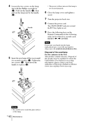
... Commander in until it is not secured properly. 6 Close the lamp cover and tighten a screw. 7 Turn the projector back over. 8 Connect the power cord. Tighten the two screws (2). Hold down the handle to replace (3). • The power will not turn on if the lamp is securely in place (1). The ON/STANDBY indicator around the...
... Commander in until it is not secured properly. 6 Close the lamp cover and tighten a screw. 7 Turn the projector back over. 8 Connect the power cord. Tighten the two screws (2). Hold down the handle to replace (3). • The power will not turn on if the lamp is securely in place (1). The ON/STANDBY indicator around the...
Operating Instructions
Page 46
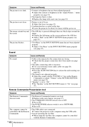
menu properly (see page 33). • The lamp has burnt or dims. c Replace the lamp with the power on the Remote Commander or adjust "Volume" in the INPUT SETTING menu properly (see page 41). c Leave the projector for about two hours with a new one (see page 35). The picture flickers. •...; The audio connecting cable is set to "On" (see page 35). Symptom Cause and Remedy The picture is not adjusted properly. c Connect the projector to PJ. Sound Symptom No sound. c Press the AUDIO MUTING key to OFF. GB 46 Maintenance c Adjust the focus (see page 16). •...
menu properly (see page 33). • The lamp has burnt or dims. c Replace the lamp with the power on the Remote Commander or adjust "Volume" in the INPUT SETTING menu properly (see page 41). c Leave the projector for about two hours with a new one (see page 35). The picture flickers. •...; The audio connecting cable is set to "On" (see page 35). Symptom Cause and Remedy The picture is not adjusted properly. c Connect the projector to PJ. Sound Symptom No sound. c Press the AUDIO MUTING key to OFF. GB 46 Maintenance c Adjust the focus (see page 16). •...
Operating Instructions
Page 47
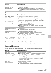
...Yes V No v High temp.! c When using the projector at a high altitude. The LAMP/COVER indicator lights up. • The lamp has reached the end of 1,500 m or higher, set to cool down . c Consult with qualified Sony personnel. not function. Symptom The computer cannot be controlled with...see if nothing is blocking the ventilation holes. • The projector is designed to see pages 42 and 43). • The lens protector does not open due to high altitude mode on the power again. c The presentation tool is used . c Replace the lamp (see page 37). flashes.
...Yes V No v High temp.! c When using the projector at a high altitude. The LAMP/COVER indicator lights up. • The lamp has reached the end of 1,500 m or higher, set to cool down . c Consult with qualified Sony personnel. not function. Symptom The computer cannot be controlled with...see if nothing is blocking the ventilation holes. • The projector is designed to see pages 42 and 43). • The lens protector does not open due to high altitude mode on the power again. c The presentation tool is used . c Replace the lamp (see page 37). flashes.
Operating Instructions
Page 48
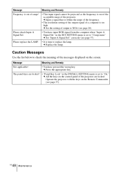
...within the range of the frequency. • The resolution setting of the output signal of a computer is time to replace the lamp. c Replace the lamp. c All the keys on the control panel of the projector are locked ! • "Panel Key Lock" in the SET SETTING menu is set to "On." Message Meaning and... on the Remote Commander (see page 37). c Press the appropriate key. c Set the setting of output to XGA (see page 37). Operate the projector with the keys on the screen. Please replace the LAMP. • It is too high. in the INSTALL SETTING menu is out of the acceptable range of the...
...within the range of the frequency. • The resolution setting of the output signal of a computer is time to replace the lamp. c Replace the lamp. c All the keys on the control panel of the projector are locked ! • "Panel Key Lock" in the SET SETTING menu is set to "On." Message Meaning and... on the Remote Commander (see page 37). c Press the appropriate key. c Set the setting of output to XGA (see page 37). Operate the projector with the keys on the screen. Please replace the LAMP. • It is too high. in the INSTALL SETTING menu is out of the acceptable range of the...
Operating Instructions
Page 51
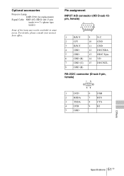
.../SCL 8 GND (B) RS-232C connector (D-sub 9 pin, female) 1 DCD 2 RXDA 3 TXDA 4 DTR 5 GND 6 DSR 7 RTS 8 CTS 9 RI Others Specifications 51 GB Optional accessories Projector Lamp LMP-C190 (for replacement) Signal Cable SMF-402 (HD D-sub 15-pin (male) y 3 × phono type (male)) Some of the items may not be available in some areas...
.../SCL 8 GND (B) RS-232C connector (D-sub 9 pin, female) 1 DCD 2 RXDA 3 TXDA 4 DTR 5 GND 6 DSR 7 RTS 8 CTS 9 RI Others Specifications 51 GB Optional accessories Projector Lamp LMP-C190 (for replacement) Signal Cable SMF-402 (HD D-sub 15-pin (male) y 3 × phono type (male)) Some of the items may not be available in some areas...
Operating Instructions
Page 64
... Image Flip 39 INPUT A/B connector pin assignment 51 Input-A Signal Sel. ........ 37 Input-C Select 37 Installation examples ..... 19 notes 7 unsuitable conditions .... 8 unsuitable installation .. 7 L Lamp Mode 40 Lamp replacement .......... 41 Lamp Timer 40 Language 38 selecting the menu language 26 Lens Control 40 Lens protector 12 Location and function of controls connector panel .......... 14 control...
... Image Flip 39 INPUT A/B connector pin assignment 51 Input-A Signal Sel. ........ 37 Input-C Select 37 Installation examples ..... 19 notes 7 unsuitable conditions .... 8 unsuitable installation .. 7 L Lamp Mode 40 Lamp replacement .......... 41 Lamp Timer 40 Language 38 selecting the menu language 26 Lens Control 40 Lens protector 12 Location and function of controls connector panel .......... 14 control...


