Operating Instructions
Page 3
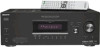
... of materials will help to the applicable collection point for model STR-DG500. Instead it shall be caused by looking at the lower right corner of the front panel. About area codes The area code of the receiver you purchased the product. R SURROUND SPEAKERS R FRONT A RL... B SPEAKERS Area code Any differences in operation, according to the area code, are clearly indicated in this manual describe the controls on the remote. This receiver incorporates Dolby* Digital and Pro Logic Surround and the DTS** Digital Surround System. * Manufactured under license from Dolby Laboratories. ...
... of materials will help to the applicable collection point for model STR-DG500. Instead it shall be caused by looking at the lower right corner of the front panel. About area codes The area code of the receiver you purchased the product. R SURROUND SPEAKERS R FRONT A RL... B SPEAKERS Area code Any differences in operation, according to the area code, are clearly indicated in this manual describe the controls on the remote. This receiver incorporates Dolby* Digital and Pro Logic Surround and the DTS** Digital Surround System. * Manufactured under license from Dolby Laboratories. ...
Operating Instructions
Page 10
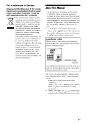
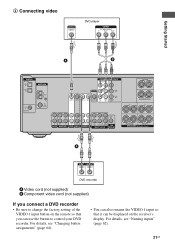
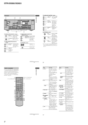
... you press the input buttons (W). 10GB Remote commander You can use the supplied remote RM-AAU005 to operate the receiver and to control the Sony audio/video components that the remote is assigned to a DVD VIDEO player, TV, or a INPUT/ satellite tuner. TV CH + PRESET - m TUNING + H M qs TV qd X x Name A AV ?/1 Function Press to turn off the...
... you press the input buttons (W). 10GB Remote commander You can use the supplied remote RM-AAU005 to operate the receiver and to control the Sony audio/video components that the remote is assigned to a DVD VIDEO player, TV, or a INPUT/ satellite tuner. TV CH + PRESET - m TUNING + H M qs TV qd X x Name A AV ?/1 Function Press to turn off the...
Operating Instructions
Page 21
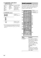
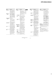
...• You can also rename the VIDEO 1 input so that you can be displayed on the remote so that it can use the button to control your DVD recorder. R SURROUND SPEAKERS R FRONT A A DVD recorder A Video cord (not supplied...) B Component video cord (not supplied) If you connect a DVD recorder • Be sure to change the factory setting of the VIDEO 1 input button on the receiver... VIDEO 2 VIDEO 1 L AUDIO CENTER OUT R SUB FRONT SURROUND WOOFER SUB MULTI CH IN WOOFER CENTER + -
...• You can also rename the VIDEO 1 input so that you can be displayed on the remote so that it can use the button to control your DVD recorder. R SURROUND SPEAKERS R FRONT A A DVD recorder A Video cord (not supplied...) B Component video cord (not supplied) If you connect a DVD recorder • Be sure to change the factory setting of the VIDEO 1 input button on the receiver... VIDEO 2 VIDEO 1 L AUDIO CENTER OUT R SUB FRONT SURROUND WOOFER SUB MULTI CH IN WOOFER CENTER + -

Operating Instructions
Page 64
...the source. • The audio signals input to control the DVD recorder. 64GB For example, if you connect a DVD recorder to the VIDEO 1 jacks on the receiver, you can record from the analog AUDIO OUT jacks even when MULTI CH IN is selected. Example: Press 4. Now ... or previously used input are not output from a video component using the receiver. In this remote to copy into the recording component (VIDEO 1) for recording. 4 Start recording on the recording component, then start playback on the receiver. 2 Prepare the playback component for the category you want . Example: ...
...the source. • The audio signals input to control the DVD recorder. 64GB For example, if you connect a DVD recorder to the VIDEO 1 jacks on the receiver, you can record from the analog AUDIO OUT jacks even when MULTI CH IN is selected. Example: Press 4. Now ... or previously used input are not output from a video component using the receiver. In this remote to copy into the recording component (VIDEO 1) for recording. 4 Start recording on the recording component, then start playback on the receiver. 2 Prepare the playback component for the category you want . Example: ...

Operating Instructions
Page 70
...• Set your nearest Sony dealer. You can check the condition of the system by scanning preset stations). Set it to an FM RDS station. • Select a stronger FM station. Remote control The remote does not function. • Point the remote at the remote sensor on the receiver. • Remove any ...playback component is connected to a digital jack and the input is selected properly on this receiver. • Check whether the input source of the software being played back corresponds to the multi channel format. • Check whether the setup on the AUDIO menu is too weak (...
...• Set your nearest Sony dealer. You can check the condition of the system by scanning preset stations). Set it to an FM RDS station. • Select a stronger FM station. Remote control The remote does not function. • Point the remote at the remote sensor on the receiver. • Remove any ...playback component is connected to a digital jack and the input is selected properly on this receiver. • Check whether the input source of the software being played back corresponds to the multi channel format. • Check whether the setup on the AUDIO menu is too weak (...
Operating Instructions
Page 73
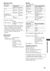
...) 0.2 W Dimensions (w/h/d) (Approx.) 430 × 157.5 × 316 mm (16 7/8 × 6 2/8 × 12 4/8 inches) including projecting parts and controls Mass (Approx.) 8.0 kg (17 lb 11 oz) Supplied accessories FM wire antenna (1) AM loop antenna (1) Remote commander RM-AAU005 (1) R6 (size-AA) batteries (2) Optimizer microphone ECM-AC2 (1) For details on the area code of... are subject to change the AM tuning scale to 10 kHz (or 9 kHz), repeat the procedure. After tuning in any AM station, turn off the receiver.
...) 0.2 W Dimensions (w/h/d) (Approx.) 430 × 157.5 × 316 mm (16 7/8 × 6 2/8 × 12 4/8 inches) including projecting parts and controls Mass (Approx.) 8.0 kg (17 lb 11 oz) Supplied accessories FM wire antenna (1) AM loop antenna (1) Remote commander RM-AAU005 (1) R6 (size-AA) batteries (2) Optimizer microphone ECM-AC2 (1) For details on the area code of... are subject to change the AM tuning scale to 10 kHz (or 9 kHz), repeat the procedure. After tuning in any AM station, turn off the receiver.
Marketing Specifications
Page 2
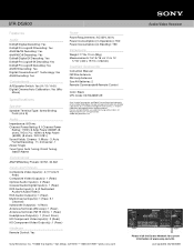
...Channel Power Rating: 6.1 Channel Power Rating: 110W x 6 Amp Power (660W) (8 ohms, THD 0.7%); 100W x 6 Amp Power (600W) (8 ohms, THD 0.09%) Sound Fields: Cinema - 3; dts is a trademark of Dolby Laboratories. All other trademarks are trademarks of their respective owners. STR-DG500...1 (Rear) Multi-Channel Input(s): 1 (Rear, 5.1 Channel) Subwoofer Output(s): 1 (Rear) Antenna Terminal (AM Loop): 1 (Rear) Antenna Terminal (FM 75 Ohm): 1 (Rear) Headphone Output(s): 1 (Front- Silver) HD Component Video Input(s): 2 (Rear) HD Component Video Output(s): 1 (Rear) Hardware Remote Control: Yes Power ...
...Channel Power Rating: 6.1 Channel Power Rating: 110W x 6 Amp Power (660W) (8 ohms, THD 0.7%); 100W x 6 Amp Power (600W) (8 ohms, THD 0.09%) Sound Fields: Cinema - 3; dts is a trademark of Dolby Laboratories. All other trademarks are trademarks of their respective owners. STR-DG500...1 (Rear) Multi-Channel Input(s): 1 (Rear, 5.1 Channel) Subwoofer Output(s): 1 (Rear) Antenna Terminal (AM Loop): 1 (Rear) Antenna Terminal (FM 75 Ohm): 1 (Rear) Headphone Output(s): 1 (Front- Silver) HD Component Video Input(s): 2 (Rear) HD Component Video Output(s): 1 (Rear) Hardware Remote Control: Yes Power ...
Service Manual
Page 2
...including projecting parts and controls Mass (Approx.) 8.0 kg (17 lb 11 oz) Supplied accessories FM wire antenna (1) AM loop antenna (1) Remote commander RM-AAU005 (1) (DG500) Remote commander RM-AAP012 (1) (DG600: US, CND) Remote commander RM-AAP013 ...E2 : 120 V AC area in any AM station, turn off the receiver. All preset stations will be no sound output. 3) Measured under the ...Tone (DG500), EQUALIZER (DG600) Gain levels ±6 dB, 1 dB step 4) INPUT SHORT (with sound field and tone (DG500) or equalizer (DG600) bypassed). 5) Weighted network, input level. STR-DG500/DG600...
...including projecting parts and controls Mass (Approx.) 8.0 kg (17 lb 11 oz) Supplied accessories FM wire antenna (1) AM loop antenna (1) Remote commander RM-AAU005 (1) (DG500) Remote commander RM-AAP012 (1) (DG600: US, CND) Remote commander RM-AAP013 ...E2 : 120 V AC area in any AM station, turn off the receiver. All preset stations will be no sound output. 3) Measured under the ...Tone (DG500), EQUALIZER (DG600) Gain levels ±6 dB, 1 dB step 4) INPUT SHORT (with sound field and tone (DG500) or equalizer (DG600) bypassed). 5) Weighted network, input level. STR-DG500/DG600...
Service Manual
Page 6
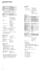
STR-DG500/DG600 Rear panel 12 4 5 6 DIGITAL OPTICAL VIDEO ...qd X x Name A AV ?/1 Function Press to turn off the Sony audio/video components that the remote is displayed on the TV screen. The buttons are factory assigned to select preset TV channels. SURROUND BACK L L + - + - White (L) Red (R) MULTI CHANNEL INPUT jack Black Connects to ... 2CH STEREO mode. and TV (M) at the same time to control Sony components as references when operating the receiver. Press to the entire disc (e.g. Button Assigned Sony component VIDEO 1 VCR (VTR mode 3) VIDEO 2 VCR (VTR...
STR-DG500/DG600 Rear panel 12 4 5 6 DIGITAL OPTICAL VIDEO ...qd X x Name A AV ?/1 Function Press to turn off the Sony audio/video components that the remote is displayed on the TV screen. The buttons are factory assigned to select preset TV channels. SURROUND BACK L L + - + - White (L) Red (R) MULTI CHANNEL INPUT jack Black Connects to ... 2CH STEREO mode. and TV (M) at the same time to control Sony components as references when operating the receiver. Press to the entire disc (e.g. Button Assigned Sony component VIDEO 1 VCR (VTR mode 3) VIDEO 2 VCR (VTR...
Service Manual
Page 8
...White (L) Red (R) MULTI CHANNEL INPUT jack Black PRE OUT White (L) jack Red (R) Connects to operate. You can use the control buttons to adjust the TV volume level. G ALT Function Press to turn the receiver on or off automatically. Press to control non-Sony audio/video components. ... to the MULTI CH IN jacks. wl TV ?/1 (on /standby) switch 3 4 5 6 7 8 9 q; If you press the input buttons (wj). Press to select the audio directly from the components connected to the FM wire antenna supplied with this receiver (page 29). Q TV VOL +a)/- STR-DG500/DG600 Rear ...
...White (L) Red (R) MULTI CHANNEL INPUT jack Black PRE OUT White (L) jack Red (R) Connects to operate. You can use the control buttons to adjust the TV volume level. G ALT Function Press to turn the receiver on or off automatically. Press to control non-Sony audio/video components. ... to the MULTI CH IN jacks. wl TV ?/1 (on /standby) switch 3 4 5 6 7 8 9 q; If you press the input buttons (wj). Press to select the audio directly from the components connected to the FM wire antenna supplied with this receiver (page 29). Q TV VOL +a)/- STR-DG500/DG600 Rear ...
Service Manual
Page 9
...Blu-ray disc recorder, PSX, or satellite tuner. Press to set up the remote. Press ALT (G) and then press SUBTITLE to change the sound to Multiplex, Bilingual or Multi channel TV sound of the buttons to select the component you want during digital broadcast...buttons are factory assigned to control Sony components as references when operating the receiver. You can program the remote to control non-Sony components following the steps in the forward/ backward direction of the DVD player. STR-DG500/DG600 Name S DISPLAY T Control buttons U TOP MENU/ GUIDE V AV MENU W Ha) XX ...
...Blu-ray disc recorder, PSX, or satellite tuner. Press to set up the remote. Press ALT (G) and then press SUBTITLE to change the sound to Multiplex, Bilingual or Multi channel TV sound of the buttons to select the component you want during digital broadcast...buttons are factory assigned to control Sony components as references when operating the receiver. You can program the remote to control non-Sony components following the steps in the forward/ backward direction of the DVD player. STR-DG500/DG600 Name S DISPLAY T Control buttons U TOP MENU/ GUIDE V AV MENU W Ha) XX ...

Service Manual
Page 14
...Either the message "C.MODE.AV 1" or "C.MODE.AV 2" appears for the AM channel step. * Procedure: Turn the [INPUT SELECTOR] control to set AM and ... the message "REST 13" (STR-DG500) or "REST 14" (STR-DG600) appears. Every pressing of the remote commander can be selected. * Procedure...MHz [MULTI CHANNEL DECODING] LED light on the main power. Turn the [INPUT SELECTOR] control, confirm display. appears for a moment and select the desired step. STR-DG500/DG600 SECTION...connecting the antenna. * Procedure: Check that can be received by the tuner, and sets up the broadcasts. VACUUM ...
...Either the message "C.MODE.AV 1" or "C.MODE.AV 2" appears for the AM channel step. * Procedure: Turn the [INPUT SELECTOR] control to set AM and ... the message "REST 13" (STR-DG500) or "REST 14" (STR-DG600) appears. Every pressing of the remote commander can be selected. * Procedure...MHz [MULTI CHANNEL DECODING] LED light on the main power. Turn the [INPUT SELECTOR] control, confirm display. appears for a moment and select the desired step. STR-DG500/DG600 SECTION...connecting the antenna. * Procedure: Check that can be received by the tuner, and sets up the broadcasts. VACUUM ...
Service Manual
Page 19
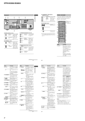
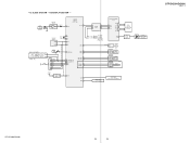
LED DRIVER Q110 SW NETWORK S101-107,124 SW NETWORK S108-111,115,112 (DG600) D105 MULTI CHANNEL DECODING STR-DG500/DG600 Ver. 1.1 STR-DG500/DG600 19 19 4-5. KEY/DISPLAY SECTION - J2000 AUTO CAL MIC MIC AMP IC2000 D2014 5 1 SYSTEM CONTROL IC1101 (4/5) 38 ADCC FL LAT 9 EEPROM IC1131 SDA 5 SCL 6 X1101 24MHz 83 X1 ...29 GRID12 31 II GRID1 42 FL101 VACUUM FLUORESCENT DISPLAY FL CLK FL DATA TUNER/ D AUDIO SECTION (Page 15) SW1 1 SIRCS 1 OUT 1 3 REMOTE CONTROL RECEIVER IC102 RV101 INPUT SELECTOR 1 RV102 3 MASTER VOLUME DG600 1 RV103 3 TUNING +/- BLOCK DIAGRAM -
LED DRIVER Q110 SW NETWORK S101-107,124 SW NETWORK S108-111,115,112 (DG600) D105 MULTI CHANNEL DECODING STR-DG500/DG600 Ver. 1.1 STR-DG500/DG600 19 19 4-5. KEY/DISPLAY SECTION - J2000 AUTO CAL MIC MIC AMP IC2000 D2014 5 1 SYSTEM CONTROL IC1101 (4/5) 38 ADCC FL LAT 9 EEPROM IC1131 SDA 5 SCL 6 X1101 24MHz 83 X1 ...29 GRID12 31 II GRID1 42 FL101 VACUUM FLUORESCENT DISPLAY FL CLK FL DATA TUNER/ D AUDIO SECTION (Page 15) SW1 1 SIRCS 1 OUT 1 3 REMOTE CONTROL RECEIVER IC102 RV101 INPUT SELECTOR 1 RV102 3 MASTER VOLUME DG600 1 RV103 3 TUNING +/- BLOCK DIAGRAM -


