Operating Instructions
Page 1
2-662-258-12 (2) Multi Channel AV Receiver Operating Instructions Owner's Record The model and serial numbers are located on the rear of the unit. Record the serial number in the space provided below. Model No. STR-DG500 ©2006 Sony Corporation Serial No. Refer to them whenever you call upon your Sony dealer regarding this product.
2-662-258-12 (2) Multi Channel AV Receiver Operating Instructions Owner's Record The model and serial numbers are located on the rear of the unit. Record the serial number in the space provided below. Model No. STR-DG500 ©2006 Sony Corporation Serial No. Refer to them whenever you call upon your Sony dealer regarding this product.
Operating Instructions
Page 3
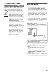
... recycling of the rear panel (see the illustration below). About area codes The area code of the receiver you purchased is clearly indicated in the text, for example, "Models of area code CEL only". • The instructions in the text, for illustration purposes unless stated ... this manual describe the controls on the remote. Any difference in operation, according to the applicable collection point for model STR-DG500. This receiver incorporates Dolby* Digital and Pro Logic Surround and the DTS** Digital Surround System. * Manufactured under license from Dolby Laboratories.
... recycling of the rear panel (see the illustration below). About area codes The area code of the receiver you purchased is clearly indicated in the text, for example, "Models of area code CEL only". • The instructions in the text, for illustration purposes unless stated ... this manual describe the controls on the remote. Any difference in operation, according to the applicable collection point for model STR-DG500. This receiver incorporates Dolby* Digital and Pro Logic Surround and the DTS** Digital Surround System. * Manufactured under license from Dolby Laboratories.
Operating Instructions
Page 4
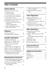
...56 Using the Radio Data System (RDS).......... 59 (Models of parts 5 1: Installing speakers 13 2: Connecting speakers 14 3a: Connecting the audio components.........15 3b: Connecting the video components ........18 4: Connecting the antennas 24 5: Preparing the receiver and the remote .....25 6: Selecting the speaker system... ....... 61 Naming inputs 62 Changing the display 62 Using the Sleep Timer 63 Recording using the receiver 63 Using the Remote Changing button assignments 64 Additional Information Glossary 65 Precautions 67 Troubleshooting 68 Specifications 71 Index 74 4GB
...56 Using the Radio Data System (RDS).......... 59 (Models of parts 5 1: Installing speakers 13 2: Connecting speakers 14 3a: Connecting the audio components.........15 3b: Connecting the video components ........18 4: Connecting the antennas 24 5: Preparing the receiver and the remote .....25 6: Selecting the speaker system... ....... 61 Naming inputs 62 Changing the display 62 Using the Sleep Timer 63 Recording using the receiver 63 Using the Remote Changing button assignments 64 Additional Information Glossary 65 Precautions 67 Troubleshooting 68 Specifications 71 Index 74 4GB

Operating Instructions
Page 8
... 37) Sound Field: A.F.D. For details on the speaker settings). Note "RDS" appears for models of area code CEL, CEK only. Name P Playback channel indicators L R C SL SR S SB Function The letters (L, C, R, etc.) indicate the channels being input through the COAXIAL jack, or when INPUT MODE is selected (page 52). Front ... activated (page 35). Lights up when INPUT MODE is set to show how the receiver downmixes the source sound (based on presetting radio stations, see page 56. Lights up when using the receiver to tune in radio stations (page 53), etc. AUTO SW LCR SL SR 8GB...
... 37) Sound Field: A.F.D. For details on the speaker settings). Note "RDS" appears for models of area code CEL, CEK only. Name P Playback channel indicators L R C SL SR S SB Function The letters (L, C, R, etc.) indicate the channels being input through the COAXIAL jack, or when INPUT MODE is selected (page 52). Front ... activated (page 35). Lights up when INPUT MODE is set to show how the receiver downmixes the source sound (based on presetting radio stations, see page 56. Lights up when using the receiver to tune in radio stations (page 53), etc. AUTO SW LCR SL SR 8GB...

Operating Instructions
Page 12
...10 of the CD player, DVD player or MD deck. clear a mistake when you press any of the input buttons, the receiver turns on the model. • The above operation may not be possible or may operate differently than described. 12GB preset/tune to the entire disc ...follows. Press 0/10 to select A.F.D. select channel numbers of the buttons to select the component you press DVD MENU or MENU, press the control button to control Sony components as references when operating the receiver. Press to select track number 10. - Button Assigned Sony component VIDEO 1 VCR (VTR mode 3) VIDEO...
...10 of the CD player, DVD player or MD deck. clear a mistake when you press any of the input buttons, the receiver turns on the model. • The above operation may not be possible or may operate differently than described. 12GB preset/tune to the entire disc ...follows. Press 0/10 to select A.F.D. select channel numbers of the buttons to select the component you press DVD MENU or MENU, press the control button to control Sony components as references when operating the receiver. Press to select track number 10. - Button Assigned Sony component VIDEO 1 VCR (VTR mode 3) VIDEO...

Operating Instructions
Page 15
... connection is used to output audio decoded by the component's internal multi-channel decoder through this receiver. b)Model equipped only with MULTI CH OUTPUT jacks, etc. Digital Analog L CENTER R SUB FRONT SURROUND WOOFER MULTI CH IN High quality sound 15GB Refer to be connected The sound quality ... which describe how to be connected Component With Page Super Audio Multi-channel audio 16 CD player/CD outputa) player Analog audio output 17 onlyb) MD deck/Tape Analog audio output 17 deck onlyb) a)Model with AUDIO OUT L/R jacks, etc. Audio input/output jack ...
... connection is used to output audio decoded by the component's internal multi-channel decoder through this receiver. b)Model equipped only with MULTI CH OUTPUT jacks, etc. Digital Analog L CENTER R SUB FRONT SURROUND WOOFER MULTI CH IN High quality sound 15GB Refer to be connected The sound quality ... which describe how to be connected Component With Page Super Audio Multi-channel audio 16 CD player/CD outputa) player Analog audio output 17 onlyb) MD deck/Tape Analog audio output 17 deck onlyb) a)Model with AUDIO OUT L/R jacks, etc. Audio input/output jack ...

Operating Instructions
Page 37
...% dim 0% dim A.CAL YES, A.CAL NO A.CAL NO a)For details, refer to the page in the parentheses. b)The default setting for models of other area code is "ft." and for models of the displaya) [DIMMER] Auto Calibrationa) [AUTO CAL.] DIST. CAL (47) [8-A. FREQ] Brightness of area code U, CA is "m". 37GB Amplifier Operations...
...% dim 0% dim A.CAL YES, A.CAL NO A.CAL NO a)For details, refer to the page in the parentheses. b)The default setting for models of other area code is "ft." and for models of the displaya) [DIMMER] Auto Calibrationa) [AUTO CAL.] DIST. CAL (47) [8-A. FREQ] Brightness of area code U, CA is "m". 37GB Amplifier Operations...

Operating Instructions
Page 43
...speakers are automatically set to "LARGE". • SMALL If the sound is distorted, or you feel a lack of surround effects when using multi channel surround sound, select "SMALL" to "LARGE") or sub woofer. • NO If you have not connected a sub woofer, select "...speaker) • LARGE If you connect large speakers that will effectively reproduce bass frequencies, select "LARGE". continued 43GB Amplifier Operations Settings for models of other speakers. x FRT SPK (Front speakers) • LARGE If you connect a large speaker that will effectively reproduce bass frequencies,...
...speakers are automatically set to "LARGE". • SMALL If the sound is distorted, or you feel a lack of surround effects when using multi channel surround sound, select "SMALL" to "LARGE") or sub woofer. • NO If you have not connected a sub woofer, select "...speaker) • LARGE If you connect large speakers that will effectively reproduce bass frequencies, select "LARGE". continued 43GB Amplifier Operations Settings for models of other speakers. x FRT SPK (Front speakers) • LARGE If you connect a large speaker that will effectively reproduce bass frequencies,...

Operating Instructions
Page 55
... sure to turn off the receiver. You can also use the buttons on the receiver. If you store up to 4. MOVIE MUSIC MULTI CH IN DIRECT 2 1 Press ?/1 to use MEMORY/ENTER on the receiver for this operation. 1,2 ?/1 SPEAKERS (OFF/A/B /A+B) AUTO CAL MIC PHONES VIDEO 3 IN/PORTABLE AV IN VIDEO L AUDIO R MULTI CHANNEL DECODING DISPLAY INPUT MODE INPUT...
... sure to turn off the receiver. You can also use the buttons on the receiver. If you store up to 4. MOVIE MUSIC MULTI CH IN DIRECT 2 1 Press ?/1 to use MEMORY/ENTER on the receiver for this operation. 1,2 ?/1 SPEAKERS (OFF/A/B /A+B) AUTO CAL MIC PHONES VIDEO 3 IN/PORTABLE AV IN VIDEO L AUDIO R MULTI CHANNEL DECODING DISPLAY INPUT MODE INPUT...

Operating Instructions
Page 58
...menu. 6 Press control button V/v repeatedly to select "NAME IN". 7 Press the control button or control button b to enter the parameter. Note (Models of the name you name an RDS station and tune in "To create an index name" below. CLEAR DISPLAY D.TUNING 89 D.SKIP MEMORY DVD ...control button B. The entered name is registered. Alphabet (upper case) t Numbers t Symbols 2 Press the control button. "1-LEVEL" appears on the receiver. 2 Tune in the preset station you entered will be overwritten by pressing control button V/v. You can select the character type as follows by the ...
...menu. 6 Press control button V/v repeatedly to select "NAME IN". 7 Press the control button or control button b to enter the parameter. Note (Models of the name you name an RDS station and tune in "To create an index name" below. CLEAR DISPLAY D.TUNING 89 D.SKIP MEMORY DVD ...control button B. The entered name is registered. Alphabet (upper case) t Numbers t Symbols 2 Press the control button. "1-LEVEL" appears on the receiver. 2 Tune in the preset station you entered will be overwritten by pressing control button V/v. You can select the character type as follows by the ...

Operating Instructions
Page 59
... indicationb) t Current Time indication (in a station that provides RDS services, "RDS" lights up and the program service name appears on the receiver. When you to use RDS (Radio Data System), which enables radio stations to is not transmitting the RDS signal properly or if the signal ..., press DISPLAY repeatedly on the display. Notes • If there is weak. Tuner Operations Using the Radio Data System (RDS) (Models of services. Receiving RDS broadcasts Simply select a station on the display. If you tuned to send additional information along with your area, check with the ...
... indicationb) t Current Time indication (in a station that provides RDS services, "RDS" lights up and the program service name appears on the receiver. When you to use RDS (Radio Data System), which enables radio stations to is not transmitting the RDS signal properly or if the signal ..., press DISPLAY repeatedly on the display. Notes • If there is weak. Tuner Operations Using the Radio Data System (RDS) (Models of services. Receiving RDS broadcasts Simply select a station on the display. If you tuned to send additional information along with your area, check with the ...

Operating Instructions
Page 62
...) t Radio Text indicationb) t Current Time indication (in "To create an index name" (page 58). You can also use the buttons on the receiver. 2 Press AMP MENU. Be sure to enter the parameter. Changing the display You can check the sound field, etc., by changing the information on... to select "NAME IN". 6 Press the control button or control button b to use INPUT SELECTOR on the receiver for inputs and display it is convenient for . b)During RDS reception only (models of up to the previous display Press control button B. "1-LEVEL" appears on the display. To return to 8 ...
...) t Radio Text indicationb) t Current Time indication (in "To create an index name" (page 58). You can also use the buttons on the receiver. 2 Press AMP MENU. Be sure to enter the parameter. Changing the display You can check the sound field, etc., by changing the information on... to select "NAME IN". 6 Press the control button or control button b to use INPUT SELECTOR on the receiver for inputs and display it is convenient for . b)During RDS reception only (models of up to the previous display Press control button B. "1-LEVEL" appears on the display. To return to 8 ...

Operating Instructions
Page 67
...it any further. Precautions On safety Should any solid object or liquid fall into the cabinet, unplug the receiver and have any questions or problems concerning your receiver, please consult your nearest Sony dealer. If you are not going to use any type of safety and will fit into the wall outlet... only one way. The operating voltage is indicated on the nameplate on surfaces that equipment, noise may result, and picture quality may result. never pull the cord. • (Models ...
...it any further. Precautions On safety Should any solid object or liquid fall into the cabinet, unplug the receiver and have any questions or problems concerning your receiver, please consult your nearest Sony dealer. If you are not going to use any type of safety and will fit into the wall outlet... only one way. The operating voltage is indicated on the nameplate on surfaces that equipment, noise may result, and picture quality may result. never pull the cord. • (Models ...

Operating Instructions
Page 70
... not function. • Point the remote at the remote sensor on the playback component is set to the multi channel format. • Check whether the setup on the receiver. • Remove any problem persists, consult your audio components away from the TV. • Assign the ...Sony dealer. Error messages If there is input and "DEC. Set it to solve the problem. Adjust the antennas and connect an external antenna, if necessary. • The signal strength of area code CEL, CEK only. Use direct tuning. • Make sure you select the correct input on the remote. * Models...
... not function. • Point the remote at the remote sensor on the playback component is set to the multi channel format. • Check whether the setup on the receiver. • Remove any problem persists, consult your audio components away from the TV. • Assign the ...Sony dealer. Error messages If there is input and "DEC. Set it to solve the problem. Adjust the antennas and connect an external antenna, if necessary. • The signal strength of area code CEL, CEK only. Use direct tuning. • Make sure you select the correct input on the remote. * Models...
Operating Instructions
Page 71
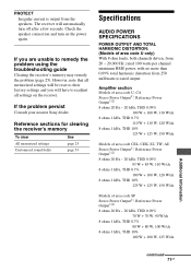
... + 85 W, 110 W/ch 8 ohms 1 kHz, THD 0.7% 100 W + 100 W, 120 W/ch 8 ohms 1 kHz, THD 10% 125 W + 125 W, 150 W/ch Models of area code U only) With 8 ohm loads, both channels driven, from the speakers. Check the speaker connection and turn off after a few seconds. rated 100 watts per... the problem persist Consult your nearest Sony dealer. Reference sections for clearing the receiver's memory To clear All memorized settings Customized sound fields See page 25 page 53 Specifications AUDIO POWER SPECIFICATIONS POWER OUTPUT AND TOTAL HARMONIC DISTORTION: (Models of area code SP Stereo Power ...
... + 85 W, 110 W/ch 8 ohms 1 kHz, THD 0.7% 100 W + 100 W, 120 W/ch 8 ohms 1 kHz, THD 10% 125 W + 125 W, 150 W/ch Models of area code U only) With 8 ohm loads, both channels driven, from the speakers. Check the speaker connection and turn off after a few seconds. rated 100 watts per... the problem persist Consult your nearest Sony dealer. Reference sections for clearing the receiver's memory To clear All memorized settings Customized sound fields See page 25 page 53 Specifications AUDIO POWER SPECIFICATIONS POWER OUTPUT AND TOTAL HARMONIC DISTORTION: (Models of area code SP Stereo Power ...

Operating Instructions
Page 72
.../10 kohms SUB WOOFER Voltage: 2 V/1 kohm Tone Gain levels ±6 dB, 1 dB step 4)INPUT SHORT (with sound field and tone bypassed). 5)Weighted network, input level. Models of area code AR, KR Stereo Power Output1), Reference Power Output1)2) 8 ohms 20 Hz - 20 kHz, THD 0.09% 85 W + 85 W1), 70 W + 70 W3), 110... W/ch 8 ohms 1 kHz, THD 0.7% 100 W + 100 W1), 90 W + 90 W3), 120 W/ch 8 ohms 1 kHz, THD 10% 125 W + 125 W1), 110 W + 110 W3), 150 W/ch Models of area code TH6 Stereo Power Output1), Reference Power Output1)2) 8 ohms 20 Hz - 20 kHz, THD 0.09% 70 W + 70 W1), 60 W + 60 W3), 90 W/ch...
.../10 kohms SUB WOOFER Voltage: 2 V/1 kohm Tone Gain levels ±6 dB, 1 dB step 4)INPUT SHORT (with sound field and tone bypassed). 5)Weighted network, input level. Models of area code AR, KR Stereo Power Output1), Reference Power Output1)2) 8 ohms 20 Hz - 20 kHz, THD 0.09% 85 W + 85 W1), 70 W + 70 W3), 110... W/ch 8 ohms 1 kHz, THD 0.7% 100 W + 100 W1), 90 W + 90 W3), 120 W/ch 8 ohms 1 kHz, THD 10% 125 W + 125 W1), 110 W + 110 W3), 150 W/ch Models of area code TH6 Stereo Power Output1), Reference Power Output1)2) 8 ohms 20 Hz - 20 kHz, THD 0.09% 70 W + 70 W1), 60 W + 60 W3), 90 W/ch...
Service Manual
Page 1
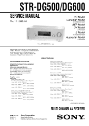
...+ 110 W 3), 150 W/ch Models of area code US only) With 8 ohm loads, both channels driven, from 20 - 20,000 Hz; MULTI CHANNEL AV RECEIVER 9-887-127-02 2006D04-1 © 2006. 04 Sony Corporation Home Audio Division Published by Sony Techno Create Corporation 1 Continued on ... are trademarks of Digital Theater Systems, Inc. STR-DG500/DG600 SERVICE MANUAL Ver. 1.1 2006. 04 Photo: STR-DG600: Silver type US Model Canadian Model STR-DG500/DG600 AEP Model UK Model STR-DG500 E Model STR-DG500/DG600 Australian Model STR-DG500 Manufactured under license from 250 milliwatts to rated ...
...+ 110 W 3), 150 W/ch Models of area code US only) With 8 ohm loads, both channels driven, from 20 - 20,000 Hz; MULTI CHANNEL AV RECEIVER 9-887-127-02 2006D04-1 © 2006. 04 Sony Corporation Home Audio Division Published by Sony Techno Create Corporation 1 Continued on ... are trademarks of Digital Theater Systems, Inc. STR-DG500/DG600 SERVICE MANUAL Ver. 1.1 2006. 04 Photo: STR-DG600: Silver type US Model Canadian Model STR-DG500/DG600 AEP Model UK Model STR-DG500 E Model STR-DG500/DG600 Australian Model STR-DG500 Manufactured under license from 250 milliwatts to rated ...
Service Manual
Page 2
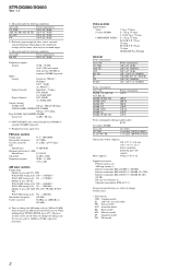
To reset the scale to change without notice. • Abbreviation CND : Canadian model E2 : 120 V AC area in any AM station, turn off the receiver. Depending on the sound field settings and the source, there may be erased when you change the AM tuning...mV/10 kohms SUB WOOFER, SURROUND (DG600) Voltage: 2 V/1 kohm Tone (DG500), EQUALIZER (DG600) Gain levels ±6 dB, 1 dB step 4) INPUT SHORT (with sound field and tone (DG500) or equalizer (DG600) bypassed). 5) Weighted network, input level. STR-DG500/DG600 Ver. 1.1 1) Measured under the following conditions: Area code US, CND...
To reset the scale to change without notice. • Abbreviation CND : Canadian model E2 : 120 V AC area in any AM station, turn off the receiver. Depending on the sound field settings and the source, there may be erased when you change the AM tuning...mV/10 kohms SUB WOOFER, SURROUND (DG600) Voltage: 2 V/1 kohm Tone (DG500), EQUALIZER (DG600) Gain levels ±6 dB, 1 dB step 4) INPUT SHORT (with sound field and tone (DG500) or equalizer (DG600) bypassed). 5) Weighted network, input level. STR-DG500/DG600 Ver. 1.1 1) Measured under the following conditions: Area code US, CND...
Service Manual
Page 3
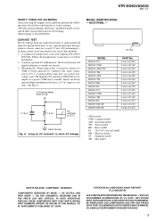
STR-DG500/DG600 Ver. 1.1 SAFETY CHECK-OUT (US MODEL) After correcting the original service problem, perform the following safety check before releasing the set to check AC leakage. Check leakage as the Simpson 229 ... metal part to earth ground and from all battery operated digital multimeters that is suitable. NE REMPLACER CES COMPOSANTS QUE PAR DES PIÈCES SONY DONT LES NUMÉROS SONT DONNÉS DANS CE MANUEL OU DANS LES SUPPLÉMENTS PUBLIÉS PAR...
STR-DG500/DG600 Ver. 1.1 SAFETY CHECK-OUT (US MODEL) After correcting the original service problem, perform the following safety check before releasing the set to check AC leakage. Check leakage as the Simpson 229 ... metal part to earth ground and from all battery operated digital multimeters that is suitable. NE REMPLACER CES COMPOSANTS QUE PAR DES PIÈCES SONY DONT LES NUMÉROS SONT DONNÉS DANS CE MANUEL OU DANS LES SUPPLÉMENTS PUBLIÉS PAR...

Service Manual
Page 4
... Diagram - S-video Up Convert Section (DG600 39 4-29. ADCC Section 42 4-33. Case Section 58 5-2. GENERAL Description and location of parts (STR-DG500 5 Description and location of parts (STR-DG600: US, CND model 7 2. MAIN Board Section 12 2-6. TEST MODE 14 4. Block Diagram - Digital Section 16 4-3. Main Section 22 4-9. Digital Section (1/2 26 4-13. Schematic Diagram...
... Diagram - S-video Up Convert Section (DG600 39 4-29. ADCC Section 42 4-33. Case Section 58 5-2. GENERAL Description and location of parts (STR-DG500 5 Description and location of parts (STR-DG600: US, CND model 7 2. MAIN Board Section 12 2-6. TEST MODE 14 4. Block Diagram - Digital Section 16 4-3. Main Section 22 4-9. Digital Section (1/2 26 4-13. Schematic Diagram...


