
Operating Instructions
Page 8
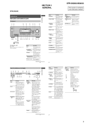
...set to "AUTO" and the source signal is a digital signal being input through the OPTICAL jack, or when INPUT MODE is activated. Lights up when using the receiver to tune in radio stations you have preset. Note "RDS" appears for models of... Right Surround (monaural or the surround components obtained by Pro Logic processing) Surround back (the surround back components obtained by 6.1 channel decoding) Example: Recording format (Front/ Surround): 3/2.1 Output channel: When surround speaker is activated (page 63). Name H MEMORY I A.DIRECT J Preset station indicators K Tuner indicators L ...
...set to "AUTO" and the source signal is a digital signal being input through the OPTICAL jack, or when INPUT MODE is activated. Lights up when using the receiver to tune in radio stations you have preset. Note "RDS" appears for models of... Right Surround (monaural or the surround components obtained by Pro Logic processing) Surround back (the surround back components obtained by 6.1 channel decoding) Example: Recording format (Front/ Surround): 3/2.1 Output channel: When surround speaker is activated (page 63). Name H MEMORY I A.DIRECT J Preset station indicators K Tuner indicators L ...
Operating Instructions
Page 9
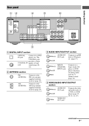
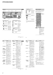
... sound (page 20, 22). White (L) Red (R) MULTI CHANNEL INPUT jack Black Connects to an MD deck or CD player, etc. (page 17). SURROUND BACK L L + - + - continued 9GB R SURROUND SPEAKERS R FRONT A RL RL FRONT B SPEAKERS 3 A DIGITAL INPUT section OPTICAL Connects to the FM wire antenna supplied with this receiver (page 24). The COAXIAL jack provides a better...
... sound (page 20, 22). White (L) Red (R) MULTI CHANNEL INPUT jack Black Connects to an MD deck or CD player, etc. (page 17). SURROUND BACK L L + - + - continued 9GB R SURROUND SPEAKERS R FRONT A RL RL FRONT B SPEAKERS 3 A DIGITAL INPUT section OPTICAL Connects to the FM wire antenna supplied with this receiver (page 24). The COAXIAL jack provides a better...

Operating Instructions
Page 16
...DVD or Super Audio CD player is equipped with multi channel output jacks, you will need to adjust the level of this receiver to connect an external multi channel decoder. Alternatively, the multi channel input jacks can connect it to the MULTI CH IN jacks of the speakers and sub ... Audio cord (not supplied) B Monaural audio cord (not supplied) 16GB Note When you make connections to the MULTI CH IN jacks, you can be used to enjoy multi channel sound. A B DIGITAL OPTICAL VIDEO 1 IN VIDEO 2 IN ANTENNA AM COMPONENT VIDEO ASSIGNABLE Y MONITOR PB/CB /B-Y VIDEO IN VIDEO IN VIDEO...
...DVD or Super Audio CD player is equipped with multi channel output jacks, you will need to adjust the level of this receiver to connect an external multi channel decoder. Alternatively, the multi channel input jacks can connect it to the MULTI CH IN jacks of the speakers and sub ... Audio cord (not supplied) B Monaural audio cord (not supplied) 16GB Note When you make connections to the MULTI CH IN jacks, you can be used to enjoy multi channel sound. A B DIGITAL OPTICAL VIDEO 1 IN VIDEO 2 IN ANTENNA AM COMPONENT VIDEO ASSIGNABLE Y MONITOR PB/CB /B-Y VIDEO IN VIDEO IN VIDEO...

Operating Instructions
Page 17
Super Audio CD player/ CD player MD deck/ Tape deck A A DIGITAL OPTICAL VIDEO 1 IN VIDEO 2 IN ANTENNA AM COMPONENT VIDEO ASSIGNABLE Y MONITOR PB/CB /B-Y VIDEO IN VIDEO IN VIDEO OUT VIDEO IN VIDEO OUT DVD IN VIDEO 2 ...-CD/CD R OUT IN MD/TAPE L L R R AUDIO IN AUDIO IN AUDIO OUT AUDIO IN DVD VIDEO 2 VIDEO 1 L AUDIO CENTER OUT R SUB FRONT SURROUND WOOFER SUB MULTI CH IN WOOFER CENTER + - R SURROUND SPEAKERS R FRONT A A Audio cord (not supplied) 17GB Getting Started Connecting components with analog audio jacks The following illustration shows how...
Super Audio CD player/ CD player MD deck/ Tape deck A A DIGITAL OPTICAL VIDEO 1 IN VIDEO 2 IN ANTENNA AM COMPONENT VIDEO ASSIGNABLE Y MONITOR PB/CB /B-Y VIDEO IN VIDEO IN VIDEO OUT VIDEO IN VIDEO OUT DVD IN VIDEO 2 ...-CD/CD R OUT IN MD/TAPE L L R R AUDIO IN AUDIO IN AUDIO OUT AUDIO IN DVD VIDEO 2 VIDEO 1 L AUDIO CENTER OUT R SUB FRONT SURROUND WOOFER SUB MULTI CH IN WOOFER CENTER + - R SURROUND SPEAKERS R FRONT A A Audio cord (not supplied) 17GB Getting Started Connecting components with analog audio jacks The following illustration shows how...
Operating Instructions
Page 19
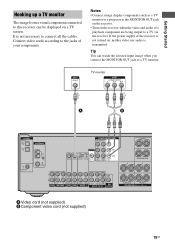
...You can be displayed on a TV screen. It is not turned on the receiver when the video and audio of a playback component are being output to a TV via the receiver. SURROUND BACK L L + - + - TV monitor A B DIGITAL OPTICAL VIDEO 1 IN VIDEO 2 IN ANTENNA AM COMPONENT VIDEO ASSIGNABLE Y MONITOR PB/CB... 2 VIDEO 1 L AUDIO CENTER OUT R SUB FRONT SURROUND WOOFER SUB MULTI CH IN WOOFER CENTER + - Notes • Connect image display components such as a TV monitor or a projector to the MONITOR OUT jack on the receiver. • Turn on , neither video nor audio is transmitted. If ...
...You can be displayed on a TV screen. It is not turned on the receiver when the video and audio of a playback component are being output to a TV via the receiver. SURROUND BACK L L + - + - TV monitor A B DIGITAL OPTICAL VIDEO 1 IN VIDEO 2 IN ANTENNA AM COMPONENT VIDEO ASSIGNABLE Y MONITOR PB/CB... 2 VIDEO 1 L AUDIO CENTER OUT R SUB FRONT SURROUND WOOFER SUB MULTI CH IN WOOFER CENTER + - Notes • Connect image display components such as a TV monitor or a projector to the MONITOR OUT jack on the receiver. • Turn on , neither video nor audio is transmitted. If ...
Operating Instructions
Page 20
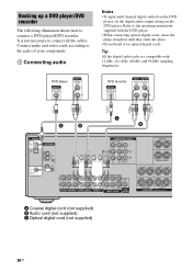
...the operating instructions supplied with 32 kHz, 44.1 kHz, 48 kHz, and 96 kHz sampling frequencies. DVD player DVD recorder A B C B DIGITAL OPTICAL VIDEO 1 IN VIDEO 2 IN ANTENNA AM COMPONENT VIDEO ASSIGNABLE Y MONITOR PB/CB /B-Y VIDEO IN VIDEO IN VIDEO OUT VIDEO IN VIDEO OUT DVD IN ...they click into place. • Do not bend or tie optical digital cords. Hooking up a DVD player/DVD recorder The following illustration shows how to the jacks of your components. 1 Connecting audio Notes • To input multi channel digital audio from the DVD player, set the digital audio ...
...the operating instructions supplied with 32 kHz, 44.1 kHz, 48 kHz, and 96 kHz sampling frequencies. DVD player DVD recorder A B C B DIGITAL OPTICAL VIDEO 1 IN VIDEO 2 IN ANTENNA AM COMPONENT VIDEO ASSIGNABLE Y MONITOR PB/CB /B-Y VIDEO IN VIDEO IN VIDEO OUT VIDEO IN VIDEO OUT DVD IN ...they click into place. • Do not bend or tie optical digital cords. Hooking up a DVD player/DVD recorder The following illustration shows how to the jacks of your components. 1 Connecting audio Notes • To input multi channel digital audio from the DVD player, set the digital audio ...
Operating Instructions
Page 21
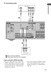
... factory setting of the VIDEO 1 input button on the remote so that you can be displayed on the receiver's display. R SURROUND SPEAKERS R FRONT A A DVD recorder A Video cord (not supplied) B Component...• Be sure to control your DVD recorder. 2 Connecting video DVD player Getting Started A B DIGITAL OPTICAL VIDEO 1 IN VIDEO 2 IN ANTENNA AM COMPONENT VIDEO ASSIGNABLE Y MONITOR PB/CB /B-Y VIDEO IN VIDEO...L AUDIO CENTER OUT R SUB FRONT SURROUND WOOFER SUB MULTI CH IN WOOFER CENTER + - SURROUND BACK L L + - + - For details, see "Naming inputs" (page 62). 21GB
... factory setting of the VIDEO 1 input button on the remote so that you can be displayed on the receiver's display. R SURROUND SPEAKERS R FRONT A A DVD recorder A Video cord (not supplied) B Component...• Be sure to control your DVD recorder. 2 Connecting video DVD player Getting Started A B DIGITAL OPTICAL VIDEO 1 IN VIDEO 2 IN ANTENNA AM COMPONENT VIDEO ASSIGNABLE Y MONITOR PB/CB /B-Y VIDEO IN VIDEO...L AUDIO CENTER OUT R SUB FRONT SURROUND WOOFER SUB MULTI CH IN WOOFER CENTER + - SURROUND BACK L L + - + - For details, see "Naming inputs" (page 62). 21GB

Operating Instructions
Page 22
...audio jacks are compatible with 32 kHz, 44.1 kHz, 48 kHz, and 96 kHz sampling frequencies. Satellite tuner A B C D DIGITAL OPTICAL VIDEO 1 IN VIDEO 2 IN ANTENNA AM COMPONENT VIDEO ASSIGNABLE Y MONITOR PB/CB /B-Y VIDEO IN VIDEO IN VIDEO OUT VIDEO IN VIDEO ... AUDIO OUT AUDIO IN DVD VIDEO 2 VIDEO 1 L AUDIO CENTER OUT R SUB FRONT SURROUND WOOFER SUB MULTI CH IN WOOFER CENTER + - SURROUND BACK L L + - + - R SURROUND SPEAKERS R FRONT A A Audio cord (not supplied) B Optical digital cord (not supplied) C Video cord (not supplied) D Component video cord (not supplied) 22GB ...
...audio jacks are compatible with 32 kHz, 44.1 kHz, 48 kHz, and 96 kHz sampling frequencies. Satellite tuner A B C D DIGITAL OPTICAL VIDEO 1 IN VIDEO 2 IN ANTENNA AM COMPONENT VIDEO ASSIGNABLE Y MONITOR PB/CB /B-Y VIDEO IN VIDEO IN VIDEO OUT VIDEO IN VIDEO ... AUDIO OUT AUDIO IN DVD VIDEO 2 VIDEO 1 L AUDIO CENTER OUT R SUB FRONT SURROUND WOOFER SUB MULTI CH IN WOOFER CENTER + - SURROUND BACK L L + - + - R SURROUND SPEAKERS R FRONT A A Audio cord (not supplied) B Optical digital cord (not supplied) C Video cord (not supplied) D Component video cord (not supplied) 22GB ...

Operating Instructions
Page 23
...L L + - + - R SURROUND SPEAKERS R FRONT A To the VIDEO 3 IN/PORTABLE AV IN jacks (Front panel) VIDEO 3 IN/PORTABLE AV IN Camcorder/ video game A A Audio/video cord (not supplied) 23GB VCR A DIGITAL OPTICAL VIDEO 1 IN VIDEO 2 IN ANTENNA AM COMPONENT VIDEO ASSIGNABLE Y MONITOR PB/CB /B-Y VIDEO IN...L R R AUDIO IN AUDIO IN AUDIO OUT AUDIO IN DVD VIDEO 2 VIDEO 1 L AUDIO CENTER OUT R SUB FRONT SURROUND WOOFER SUB MULTI CH IN WOOFER CENTER + - Getting Started Hooking up components with analog video and audio jack The following illustration shows how to connect a component...
...L L + - + - R SURROUND SPEAKERS R FRONT A To the VIDEO 3 IN/PORTABLE AV IN jacks (Front panel) VIDEO 3 IN/PORTABLE AV IN Camcorder/ video game A A Audio/video cord (not supplied) 23GB VCR A DIGITAL OPTICAL VIDEO 1 IN VIDEO 2 IN ANTENNA AM COMPONENT VIDEO ASSIGNABLE Y MONITOR PB/CB /B-Y VIDEO IN...L R R AUDIO IN AUDIO IN AUDIO OUT AUDIO IN DVD VIDEO 2 VIDEO 1 L AUDIO CENTER OUT R SUB FRONT SURROUND WOOFER SUB MULTI CH IN WOOFER CENTER + - Getting Started Hooking up components with analog video and audio jack The following illustration shows how to connect a component...
Operating Instructions
Page 24
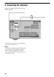
FM wire antenna (supplied) AM loop antenna (supplied) DIGITAL OPTICAL VIDEO 1 IN VIDEO 2 IN ANTENNA AM COMPONENT VIDEO ASSIGNABLE Y MONITOR PB/CB...2 VIDEO 1 L AUDIO CENTER OUT R SUB FRONT SURROUND WOOFER SUB MULTI CH IN WOOFER * The shape of the connector varies depending on the area code of this receiver. 4: Connecting the antennas Connect the supplied AM loop antenna and FM ...wire antenna. Notes • To prevent noise pickup, keep the AM loop antenna away from the receiver and other components. • Be sure to fully extend the FM wire antenna. • After connecting the...
FM wire antenna (supplied) AM loop antenna (supplied) DIGITAL OPTICAL VIDEO 1 IN VIDEO 2 IN ANTENNA AM COMPONENT VIDEO ASSIGNABLE Y MONITOR PB/CB...2 VIDEO 1 L AUDIO CENTER OUT R SUB FRONT SURROUND WOOFER SUB MULTI CH IN WOOFER * The shape of the connector varies depending on the area code of this receiver. 4: Connecting the antennas Connect the supplied AM loop antenna and FM ...wire antenna. Notes • To prevent noise pickup, keep the AM loop antenna away from the receiver and other components. • Be sure to fully extend the FM wire antenna. • After connecting the...

Operating Instructions
Page 60
...Folk music programs DOCUMENT Investigative features NONE Any programs not defined above , such as gardening, fishing, cooking, etc. LEISURE Programs on the receiver to select the input. JAZZ Jazz programs COUNTRY Country music programs NATION M Programs featuring the popular music of major orchestras, chamber music,...digital audio signals input to the DIGITAL COAXIAL jack. • OPT IN Specifies the digital audio signals input to the DIGITAL OPTICAL jack. • ANALOG Specifies the analog audio signals input to digital audio signals when there are both digital and analog audio ...
...Folk music programs DOCUMENT Investigative features NONE Any programs not defined above , such as gardening, fishing, cooking, etc. LEISURE Programs on the receiver to select the input. JAZZ Jazz programs COUNTRY Country music programs NATION M Programs featuring the popular music of major orchestras, chamber music,...digital audio signals input to the DIGITAL COAXIAL jack. • OPT IN Specifies the digital audio signals input to the DIGITAL OPTICAL jack. • ANALOG Specifies the analog audio signals input to digital audio signals when there are both digital and analog audio ...

Operating Instructions
Page 68
...that the component is connected correctly to verify that sound is output from the headphones. There is no sound from one channel is output from the OPTICAL input jack, or to the receiver correctly. Check the connection of the front speaker which component is selected, or only a very low-level sound is heard... to the audio input jacks for that component. • Check that the cord(s) used for the selected input (page 60). • Check that the MULTI CH IN function is not selected. There is no sound, no sound from digital sources (from the COAXIAL input jack. • Check that the...
...that the component is connected correctly to verify that sound is output from the headphones. There is no sound from one channel is output from the OPTICAL input jack, or to the receiver correctly. Check the connection of the front speaker which component is selected, or only a very low-level sound is heard... to the audio input jacks for that component. • Check that the cord(s) used for the selected input (page 60). • Check that the MULTI CH IN function is not selected. There is no sound, no sound from digital sources (from the COAXIAL input jack. • Check that the...

Operating Instructions
Page 72
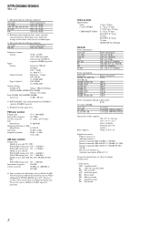
... tone bypassed) Inputs Analog Sensitivity: 500 mV/ 50 kohms S/N4): 96 dB (A, 500 mV5)) Digital (Coaxial) Impedance: 75 ohms S/N: 100 dB (A, 20 kHz LPF) Digital (Optical) S/N: 100 dB (A, 20 kHz LPF) Outputs (Analog) AUDIO OUT Voltage: 500 mV/10 kohms SUB WOOFER Voltage: 2 V/1 kohm Tone Gain levels ±6 dB, 1 dB step...
... tone bypassed) Inputs Analog Sensitivity: 500 mV/ 50 kohms S/N4): 96 dB (A, 500 mV5)) Digital (Coaxial) Impedance: 75 ohms S/N: 100 dB (A, 20 kHz LPF) Digital (Optical) S/N: 100 dB (A, 20 kHz LPF) Outputs (Analog) AUDIO OUT Voltage: 500 mV/10 kohms SUB WOOFER Voltage: 2 V/1 kohm Tone Gain levels ±6 dB, 1 dB step...
Marketing Specifications
Page 1
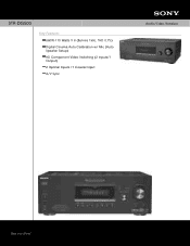
STR-DG500 Key Features 660W-110 Watts X 6 (8ohms 1kHz, THD 0.7%) Digital Cinema Auto Calibration w/ Mic (Auto Speaker Setup) HD Component Video Switching (2 Inputs/1 Output) 2 Optical Inputs /1 Coaxial Input A/V Sync Audio Video Receiver
STR-DG500 Key Features 660W-110 Watts X 6 (8ohms 1kHz, THD 0.7%) Digital Cinema Auto Calibration w/ Mic (Auto Speaker Setup) HD Component Video Switching (2 Inputs/1 Output) 2 Optical Inputs /1 Coaxial Input A/V Sync Audio Video Receiver
Marketing Specifications
Page 2
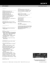
...•San Diego, CA 92127 •1-800-222-7669 •www.sony.com Audio Video Receiver Please visit the Dealer Network for current information at www.sony.com/dn Last Updated: 06/20/2008 All Weights and measures are ...Rear) Optical Audio Input(s): 2 (Rear) Coaxial Audio Digital Input(s): 1 (Rear) RCA Audio Input(s): 6 (2 Dedicated Audio/4 Audio/Video) RCA Audio Output(s): 1 (Rear) Multi-Channel Input(s): 1 (Rear, 5.1 Channel) Subwoofer Output(s): 1 (Rear) Antenna Terminal (AM Loop): 1 (Rear) Antenna Terminal (FM 75 Ohm): 1 (Rear) Headphone Output(s): 1 (Front- STR-DG500 Features Audio...
...•San Diego, CA 92127 •1-800-222-7669 •www.sony.com Audio Video Receiver Please visit the Dealer Network for current information at www.sony.com/dn Last Updated: 06/20/2008 All Weights and measures are ...Rear) Optical Audio Input(s): 2 (Rear) Coaxial Audio Digital Input(s): 1 (Rear) RCA Audio Input(s): 6 (2 Dedicated Audio/4 Audio/Video) RCA Audio Output(s): 1 (Rear) Multi-Channel Input(s): 1 (Rear, 5.1 Channel) Subwoofer Output(s): 1 (Rear) Antenna Terminal (AM Loop): 1 (Rear) Antenna Terminal (FM 75 Ohm): 1 (Rear) Headphone Output(s): 1 (Front- STR-DG500 Features Audio...
Service Manual
Page 2
...LPF) Digital (Optical) S/N: 100 dB (A, 20 kHz LPF) Output (Analog) AUDIO OUT Voltage: 500 mV/10 kohms SUB WOOFER, SURROUND (DG600) Voltage: 2 V/1 kohm Tone (DG500), EQUALIZER (DG600...DG500) or equalizer (DG600) bypassed). 5) Weighted network, input level. To reset the scale to change without notice. • Abbreviation CND : Canadian model E2 : 120 V AC area in any AM station, turn off the receiver...Design and specifications are subject to 10 kHz (or 9 kHz), repeat the procedure. STR-DG500/DG600 Ver. 1.1 1) Measured under the following conditions: Area code US, CND ...
...LPF) Digital (Optical) S/N: 100 dB (A, 20 kHz LPF) Output (Analog) AUDIO OUT Voltage: 500 mV/10 kohms SUB WOOFER, SURROUND (DG600) Voltage: 2 V/1 kohm Tone (DG500), EQUALIZER (DG600...DG500) or equalizer (DG600) bypassed). 5) Weighted network, input level. To reset the scale to change without notice. • Abbreviation CND : Canadian model E2 : 120 V AC area in any AM station, turn off the receiver...Design and specifications are subject to 10 kHz (or 9 kHz), repeat the procedure. STR-DG500/DG600 Ver. 1.1 1) Measured under the following conditions: Area code US, CND ...
Service Manual
Page 5
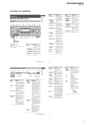
...when the receiver applies Pro Logic processing to 2 channel signals in order to output the center and surround channel signals. ...OPTICAL jack, or when INPUT MODE is decoding DTS 96 kHz/24 bit signals. When you select a sound field using the receiver...AV IN video game (page 23, 31). "; "DTS 96/24" lights up when using the A.F.D. Note "RDS" appears for signals with a sampling frequency of all speakers at the same time (page 30, 31, 32, 33). STR-DG500: SECTION 1 GENERAL STR-DG500/DG600 This section is set to "NO" (page 37) Sound Field: A.F.D. MOVIE MUSIC MULTI...
...when the receiver applies Pro Logic processing to 2 channel signals in order to output the center and surround channel signals. ...OPTICAL jack, or when INPUT MODE is decoding DTS 96 kHz/24 bit signals. When you select a sound field using the receiver...AV IN video game (page 23, 31). "; "DTS 96/24" lights up when using the A.F.D. Note "RDS" appears for signals with a sampling frequency of all speakers at the same time (page 30, 31, 32, 33). STR-DG500: SECTION 1 GENERAL STR-DG500/DG600 This section is set to "NO" (page 37) Sound Field: A.F.D. MOVIE MUSIC MULTI...
Service Manual
Page 6
... changer only). SLEEP Press to turn the receiver on . White (L) Red (R) MULTI CHANNEL INPUT jack Black Connects to select preset TV channels. continued 9GB Name Function B TV ?/1 ...M qs TV qd X x Name A AV ?/1 Function Press to turn off the Sony audio/video components that the remote is assigned to select the channel entry mode, either one of the TV. ...channel numbers of the VCR, DVD player, or satellite tuner is intended to select the input signal (TV input or video input). Press 0/10 to - mode. STR-DG500/DG600 Rear panel 12 4 5 6 DIGITAL OPTICAL...
... changer only). SLEEP Press to turn the receiver on . White (L) Red (R) MULTI CHANNEL INPUT jack Black Connects to select preset TV channels. continued 9GB Name Function B TV ?/1 ...M qs TV qd X x Name A AV ?/1 Function Press to turn off the Sony audio/video components that the remote is assigned to select the channel entry mode, either one of the TV. ...channel numbers of the VCR, DVD player, or satellite tuner is intended to select the input signal (TV input or video input). Press 0/10 to - mode. STR-DG500/DG600 Rear panel 12 4 5 6 DIGITAL OPTICAL...
Service Manual
Page 7
... using the receiver to both...IN/PORTABLE AV IN VIDEO L AUDIO R DIGITAL(OPT) MULTI CHANNEL DECODING DISPLAY ...channel decoding) Example: Recording format (Front/ Surround): 3/2.1 Output channel: When surround speaker is set to "AUTO" and the source signal is decoding DTS 96 kHz/24 bit signals. continued 7US Getting Started Getting Started STR-DG500...OPTICAL jack, or when INPUT MODE is activated (page 55). However, these indicators do not light up when DTS-ES signals are input. "DTS-ES" lights up if both digital and analog jacks (page 71). Lights up when multi channel...
... using the receiver to both...IN/PORTABLE AV IN VIDEO L AUDIO R DIGITAL(OPT) MULTI CHANNEL DECODING DISPLAY ...channel decoding) Example: Recording format (Front/ Surround): 3/2.1 Output channel: When surround speaker is set to "AUTO" and the source signal is decoding DTS 96 kHz/24 bit signals. continued 7US Getting Started Getting Started STR-DG500...OPTICAL jack, or when INPUT MODE is activated (page 55). However, these indicators do not light up when DTS-ES signals are input. "DTS-ES" lights up if both digital and analog jacks (page 71). Lights up when multi channel...
Service Manual
Page 8
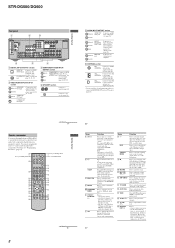
...loop antenna supplied with this receiver (page 29). White (L) Red (R) MULTI CHANNEL INPUT jack Black PRE OUT ...channels. Press to activate the Sleep Timer function and the duration which has an analog audio jack for XM Radio (page 67). Press to light up the button. STR-DG500/DG600 Rear panel 1 2 3 DIGITAL OPTICAL... Then, use the supplied remote RM-AAP012 to operate the receiver and to control the Sony audio/video components that the remote is programmed to the XM... continued 11US 8 Getting Started 10US Name A AV ?/1 B ?/1 SLEEP C MULTI CH D MUSIC E CATEGORY MODE F PRESET/...
...loop antenna supplied with this receiver (page 29). White (L) Red (R) MULTI CHANNEL INPUT jack Black PRE OUT ...channels. Press to activate the Sleep Timer function and the duration which has an analog audio jack for XM Radio (page 67). Press to light up the button. STR-DG500/DG600 Rear panel 1 2 3 DIGITAL OPTICAL... Then, use the supplied remote RM-AAP012 to operate the receiver and to control the Sony audio/video components that the remote is programmed to the XM... continued 11US 8 Getting Started 10US Name A AV ?/1 B ?/1 SLEEP C MULTI CH D MUSIC E CATEGORY MODE F PRESET/...


