Operating Instructions
Page 1
Serial No. 2-662-258-12 (2) Multi Channel AV Receiver Operating Instructions Owner's Record The model and serial numbers are located on the rear of the unit. Refer to them whenever you call upon your Sony dealer regarding this product. Model No. Record the serial number in the space provided below. STR-DG500 ©2006 Sony Corporation
Serial No. 2-662-258-12 (2) Multi Channel AV Receiver Operating Instructions Owner's Record The model and serial numbers are located on the rear of the unit. Refer to them whenever you call upon your Sony dealer regarding this product. Model No. Record the serial number in the space provided below. STR-DG500 ©2006 Sony Corporation
Operating Instructions
Page 2
WARNING This equipment has been tested and found to Part 15 of the FCC Rules. Reorient or relocate the receiving antenna. - Consult the dealer or an experienced radio/TV technician for a Class B digital device, pursuant to comply with the limits for help. ...grounding and, in this manual could void your authority to operate this equipment does cause harmful interference to radio or television reception, which the receiver is encouraged to try to constitute a risk of cable entry as chemical waste. For customers in the United States This symbol is provided to...
WARNING This equipment has been tested and found to Part 15 of the FCC Rules. Reorient or relocate the receiving antenna. - Consult the dealer or an experienced radio/TV technician for a Class B digital device, pursuant to comply with the limits for help. ...grounding and, in this manual could void your authority to operate this equipment does cause harmful interference to radio or television reception, which the receiver is encouraged to try to constitute a risk of cable entry as chemical waste. For customers in the United States This symbol is provided to...
Operating Instructions
Page 3
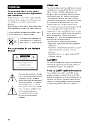
...manual are for illustration purposes unless stated otherwise. CENTER + - SURROUND BACK L L + - + - You can also use the controls on the receiver if they have the same or similar names as household waste. "Dolby", "Pro Logic", "Surround EX", and the double-D symbol are trademarks of Dolby... in this manual, models of area code U is shown on the remote. About area codes The area code of the receiver you purchased is used for model STR-DG500. R SURROUND SPEAKERS R FRONT A RL RL FRONT B SPEAKERS Area code Any differences in operation, according to conserve natural resources...
...manual are for illustration purposes unless stated otherwise. CENTER + - SURROUND BACK L L + - + - You can also use the controls on the receiver if they have the same or similar names as household waste. "Dolby", "Pro Logic", "Surround EX", and the double-D symbol are trademarks of Dolby... in this manual, models of area code U is shown on the remote. About area codes The area code of the receiver you purchased is used for model STR-DG500. R SURROUND SPEAKERS R FRONT A RL RL FRONT B SPEAKERS Area code Any differences in operation, according to conserve natural resources...
Operating Instructions
Page 4
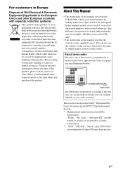
...2: Connecting speakers 14 3a: Connecting the audio components.........15 3b: Connecting the video components ........18 4: Connecting the antennas 24 5: Preparing the receiver and the remote .....25 6: Selecting the speaker system 26 7: Calibrating the appropriate settings automatically (AUTO CALIBRATION 27 8: Adjusting the speaker levels... 61 Naming inputs 62 Changing the display 62 Using the Sleep Timer 63 Recording using the receiver 63 Using the Remote Changing button assignments 64 Additional Information Glossary 65 Precautions 67 Troubleshooting 68 Specifications 71 Index 74 4GB...
...2: Connecting speakers 14 3a: Connecting the audio components.........15 3b: Connecting the video components ........18 4: Connecting the antennas 24 5: Preparing the receiver and the remote .....25 6: Selecting the speaker system 26 7: Calibrating the appropriate settings automatically (AUTO CALIBRATION 27 8: Adjusting the speaker levels... 61 Naming inputs 62 Changing the display 62 Using the Sleep Timer 63 Recording using the receiver 63 Using the Remote Changing button assignments 64 Additional Information Glossary 65 Precautions 67 Troubleshooting 68 Specifications 71 Index 74 4GB...

Operating Instructions
Page 5
... 3 IN/PORTABLE AV IN VIDEO L AUDIO R MULTI CHANNEL DECODING DISPLAY INPUT MODE INPUT SELECTOR MASTER VOLUME MEMORY/ TUNING ENTER MODE TUNING 2CH A.F.D. continued 5GB D MULTI CHANNEL Lights up when multi DECODING lamp channel audio is decoded (page 33). When you remove the cover, keep it out of selectable items appears here (page 7). E Remote sensor Receives signals from children...
... 3 IN/PORTABLE AV IN VIDEO L AUDIO R MULTI CHANNEL DECODING DISPLAY INPUT MODE INPUT SELECTOR MASTER VOLUME MEMORY/ TUNING ENTER MODE TUNING 2CH A.F.D. continued 5GB D MULTI CHANNEL Lights up when multi DECODING lamp channel audio is decoded (page 33). When you remove the cover, keep it out of selectable items appears here (page 7). E Remote sensor Receives signals from children...

Operating Instructions
Page 7
...Lights up when Dolby Digital signals are input. Lights up when DTS Neo:6 Cinema/Music decoder is not set to output the center and surround channel signals. Note When playing a Dolby Digital format disc, be sure that you have made digital connections and that INPUT MODE is activated (page...) F DTS (-ES)/ (96/24) G NEO:6 Function Lights up when DTS-ES signals are input. "DTS-ES" lights up when the receiver applies Pro Logic processing to 2 channel signals in order to "ANALOG" (page 60). DIGITAL EX" lights up when DTS signals are input. Lights up when Dolby Digital Surround EX...
...Lights up when Dolby Digital signals are input. Lights up when DTS Neo:6 Cinema/Music decoder is not set to output the center and surround channel signals. Note When playing a Dolby Digital format disc, be sure that you have made digital connections and that INPUT MODE is activated (page...) F DTS (-ES)/ (96/24) G NEO:6 Function Lights up when DTS-ES signals are input. "DTS-ES" lights up when the receiver applies Pro Logic processing to 2 channel signals in order to "ANALOG" (page 60). DIGITAL EX" lights up when DTS signals are input. Lights up when Dolby Digital Surround EX...

Operating Instructions
Page 8
...(page 57), etc., is activated (page 35). Lights up when using the receiver to "NO" (page 37) Sound Field: A.F.D. Name P Playback channel indicators L R C SL SR S SB Function The letters (L, C, R, etc.) indicate the channels being input through the OPTICAL jack, or when INPUT MODE is set to "OPT...) Example: Recording format (Front/ Surround): 3/2.1 Output channel: When surround speaker is activated (page 63). Note "RDS" appears for models of area code CEL, CEK only. Lights up when using the receiver to "AUTO" and the source signal is a digital signal being played back. ...
...(page 57), etc., is activated (page 35). Lights up when using the receiver to "NO" (page 37) Sound Field: A.F.D. Name P Playback channel indicators L R C SL SR S SB Function The letters (L, C, R, etc.) indicate the channels being input through the OPTICAL jack, or when INPUT MODE is set to "OPT...) Example: Recording format (Front/ Surround): 3/2.1 Output channel: When surround speaker is activated (page 63). Note "RDS" appears for models of area code CEL, CEK only. Lights up when using the receiver to "AUTO" and the source signal is a digital signal being played back. ...
Operating Instructions
Page 9
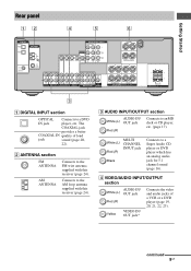
...DVD player (page 19, 20, 21, 22, 23). B ANTENNA section FM ANTENNA AM ANTENNA Connects to the FM wire antenna supplied with this receiver (page 24). D VIDEO/AUDIO INPUT/OUTPUT section AUDIO IN/ White (L) OUT jack Red (R) Yellow VIDEO IN/ OUT jack* Connects the video...jack for 5.1 channel sound (page 16). R SURROUND SPEAKERS R FRONT A RL RL FRONT B SPEAKERS 3 A DIGITAL INPUT section OPTICAL Connects to an MD deck or CD player, etc. (page 17). White (L) Red (R) MULTI CHANNEL INPUT jack Black Connects to the AM loop antenna supplied with this receiver (page 24...
...DVD player (page 19, 20, 21, 22, 23). B ANTENNA section FM ANTENNA AM ANTENNA Connects to the FM wire antenna supplied with this receiver (page 24). D VIDEO/AUDIO INPUT/OUTPUT section AUDIO IN/ White (L) OUT jack Red (R) Yellow VIDEO IN/ OUT jack* Connects the video...jack for 5.1 channel sound (page 16). R SURROUND SPEAKERS R FRONT A RL RL FRONT B SPEAKERS 3 A DIGITAL INPUT section OPTICAL Connects to an MD deck or CD player, etc. (page 17). White (L) Red (R) MULTI CHANNEL INPUT jack Black Connects to the AM loop antenna supplied with this receiver (page 24...
Operating Instructions
Page 10
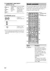
You OUTPUT can use the supplied remote RM-AAU005 to operate the receiver and to control the Sony audio/video components that the remote is assigned to turn off the Sony audio/video components that the remote is assigned to a TV monitor (page 19). Remote...8 CLEAR qk 9 DISPLAY TOOLS MUTING qj q; TV CH + PRESET - REPLAY ADVANCE PRESET + .< > < TUNING - m TUNING + H M qs TV qd X x Name A AV ?/1 Function Press to operate (page 64). E COMPONENT VIDEO INPUT/ OUTPUT section Green Blue Red COMPONENT Connects to speakers (page 14). Connects to sub woofer (page...
You OUTPUT can use the supplied remote RM-AAU005 to operate the receiver and to control the Sony audio/video components that the remote is assigned to turn off the Sony audio/video components that the remote is assigned to a TV monitor (page 19). Remote...8 CLEAR qk 9 DISPLAY TOOLS MUTING qj q; TV CH + PRESET - REPLAY ADVANCE PRESET + .< > < TUNING - m TUNING + H M qs TV qd X x Name A AV ?/1 Function Press to operate (page 64). E COMPONENT VIDEO INPUT/ OUTPUT section Green Blue Red COMPONENT Connects to speakers (page 14). Connects to sub woofer (page...

Operating Instructions
Page 11
... E DUAL MONO Press to select the language you want during digital broadcast. D.SKIP H DVD MENU I ENTER Press to skip disc of the receiver. Press TV VOL +/- search tracks in recording standby.) x Press to stop playback of the VCR, CD player, DVD player, MD deck, or... perform menu operations. Press to start playback of all components, press ?/1 and AV ?/1 (A) at the same time. To turn the receiver on the TV screen. and TV (M) at the same time to select preset TV channels. m/M Ha) Press to select - Press TV CH +/- continued 11GB Getting ...
... E DUAL MONO Press to select the language you want during digital broadcast. D.SKIP H DVD MENU I ENTER Press to skip disc of the receiver. Press TV VOL +/- search tracks in recording standby.) x Press to stop playback of the VCR, CD player, DVD player, MD deck, or... perform menu operations. Press to start playback of all components, press ?/1 and AV ?/1 (A) at the same time. To turn the receiver on the TV screen. and TV (M) at the same time to select preset TV channels. m/M Ha) Press to select - Press TV CH +/- continued 11GB Getting ...

Operating Instructions
Page 12
...the same time to select the channel entry mode, either one of the buttons to control Sony components as references when operating the receiver. channel numbers of the satellite tuner or DVD player. of the Digital CATV terminal. Press 0/10 to select A.F.D. select channel numbers of the VCR, satellite ...the button assignments following the steps in "Changing button assignments" on the component, the above explanation is intended to select the TV channels. Button Assigned Sony component VIDEO 1 VCR (VTR mode 3) VIDEO 2 VCR (VTR mode 2) VIDEO 3 Not assigned DVD DVD player MD/TAPE ...
...the same time to select the channel entry mode, either one of the buttons to control Sony components as references when operating the receiver. channel numbers of the satellite tuner or DVD player. of the Digital CATV terminal. Press 0/10 to select A.F.D. select channel numbers of the VCR, satellite ...the button assignments following the steps in "Changing button assignments" on the component, the above explanation is intended to select the TV channels. Button Assigned Sony component VIDEO 1 VCR (VTR mode 3) VIDEO 2 VCR (VTR mode 2) VIDEO 3 Not assigned DVD DVD player MD/TAPE ...
Operating Instructions
Page 13
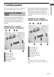
Getting Started 1: Installing speakers This receiver allows you to use a 6.1 channel system (6 speakers and one additional surround back speaker (6.1 channel) (see "Using the surround back decoding mode" on page 40). Enjoying a 5.1/6.1 channel system To fully enjoy theater-like multi channel surround sound requires five speakers (two front speakers, a center speaker, and two surround speakers) and a sub woofer...
Getting Started 1: Installing speakers This receiver allows you to use a 6.1 channel system (6 speakers and one additional surround back speaker (6.1 channel) (see "Using the surround back decoding mode" on page 40). Enjoying a 5.1/6.1 channel system To fully enjoy theater-like multi channel surround sound requires five speakers (two front speakers, a center speaker, and two surround speakers) and a sub woofer...

Operating Instructions
Page 15
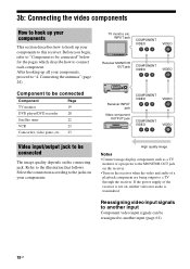
This connection is used to output audio decoded by the component's internal multi-channel decoder through this receiver. Refer to the jacks of your components. Select the connection according to the illustration that follows. Before you begin, refer to "Component to be ...antennas" (page 24). Audio input/output jack to be connected" below for the pages which describe how to be connected Component With Page Super Audio Multi-channel audio 16 CD player/CD outputa) player Analog audio output 17 onlyb) MD deck/Tape Analog audio output 17 deck onlyb) a)Model with AUDIO ...
This connection is used to output audio decoded by the component's internal multi-channel decoder through this receiver. Refer to the jacks of your components. Select the connection according to the illustration that follows. Before you begin, refer to "Component to be ...antennas" (page 24). Audio input/output jack to be connected" below for the pages which describe how to be connected Component With Page Super Audio Multi-channel audio 16 CD player/CD outputa) player Analog audio output 17 onlyb) MD deck/Tape Analog audio output 17 deck onlyb) a)Model with AUDIO ...

Operating Instructions
Page 16
... used to connect an external multi channel decoder. Connecting components with multi channel output jacks If your DVD or Super Audio CD player is equipped with multi channel output jacks, you will need to adjust the level of this receiver to enjoy multi channel sound. Alternatively, the multi channel input jacks can connect it to the MULTI CH IN jacks of the...
... used to connect an external multi channel decoder. Connecting components with multi channel output jacks If your DVD or Super Audio CD player is equipped with multi channel output jacks, you will need to adjust the level of this receiver to enjoy multi channel sound. Alternatively, the multi channel input jacks can connect it to the MULTI CH IN jacks of the...
Operating Instructions
Page 18
...player/DVD recorder 20 Satellite tuner 22 VCR 23 Camcorder, video game, etc. 23 TV monitor, etc. After hooking up your components to this receiver. If the power supply of a playback component are being output to the jacks on , neither video nor audio is transmitted. 3b: Connecting the... TV monitor or a projector to the MONITOR OUT jack on the receiver. • Turn on the receiver when the video and audio of the receiver is not on your components. Select the connection according to a TV through the receiver. Component to be connected" below for the pages which describe how to...
...player/DVD recorder 20 Satellite tuner 22 VCR 23 Camcorder, video game, etc. 23 TV monitor, etc. After hooking up your components to this receiver. If the power supply of a playback component are being output to the jacks on , neither video nor audio is transmitted. 3b: Connecting the... TV monitor or a projector to the MONITOR OUT jack on the receiver. • Turn on the receiver when the video and audio of the receiver is not on your components. Select the connection according to a TV through the receiver. Component to be connected" below for the pages which describe how to...
Operating Instructions
Page 19
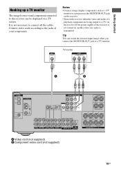
...R OUT IN MD/TAPE L L R R AUDIO IN AUDIO IN AUDIO OUT AUDIO IN DVD VIDEO 2 VIDEO 1 L AUDIO CENTER OUT R SUB FRONT SURROUND WOOFER SUB MULTI CH IN WOOFER CENTER + - SURROUND BACK L L + - + - Getting Started Hooking up a TV monitor The image from a visual component connected to a TV monitor... projector to the MONITOR OUT jack on the receiver. • Turn on , neither video nor audio is not necessary to a TV via the receiver. Connect video cords according to the jacks of the receiver is not turned on the receiver when the video and audio of a playback component...
...R OUT IN MD/TAPE L L R R AUDIO IN AUDIO IN AUDIO OUT AUDIO IN DVD VIDEO 2 VIDEO 1 L AUDIO CENTER OUT R SUB FRONT SURROUND WOOFER SUB MULTI CH IN WOOFER CENTER + - SURROUND BACK L L + - + - Getting Started Hooking up a TV monitor The image from a visual component connected to a TV monitor... projector to the MONITOR OUT jack on the receiver. • Turn on , neither video nor audio is not necessary to a TV via the receiver. Connect video cords according to the jacks of the receiver is not turned on the receiver when the video and audio of a playback component...
Operating Instructions
Page 21
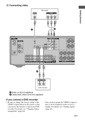
... recorder. For details, see "Changing button assignments" (page 64). • You can also rename the VIDEO 1 input so that you can be displayed on the receiver's display. For details, see "Naming inputs" (page 62). 21GB 2 Connecting video DVD player Getting Started A B DIGITAL OPTICAL VIDEO 1 IN VIDEO 2 IN ANTENNA AM COMPONENT VIDEO...-CD/CD R OUT IN MD/TAPE L L R R AUDIO IN AUDIO IN AUDIO OUT AUDIO IN DVD VIDEO 2 VIDEO 1 L AUDIO CENTER OUT R SUB FRONT SURROUND WOOFER SUB MULTI CH IN WOOFER CENTER + - SURROUND BACK L L + - + -
... recorder. For details, see "Changing button assignments" (page 64). • You can also rename the VIDEO 1 input so that you can be displayed on the receiver's display. For details, see "Naming inputs" (page 62). 21GB 2 Connecting video DVD player Getting Started A B DIGITAL OPTICAL VIDEO 1 IN VIDEO 2 IN ANTENNA AM COMPONENT VIDEO...-CD/CD R OUT IN MD/TAPE L L R R AUDIO IN AUDIO IN AUDIO OUT AUDIO IN DVD VIDEO 2 VIDEO 1 L AUDIO CENTER OUT R SUB FRONT SURROUND WOOFER SUB MULTI CH IN WOOFER CENTER + - SURROUND BACK L L + - + -
Operating Instructions
Page 24
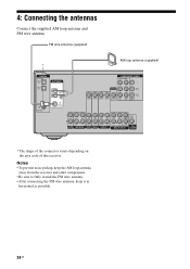
Notes • To prevent noise pickup, keep the AM loop antenna away from the receiver and other components. • Be sure to fully extend the FM wire antenna. • After connecting the FM wire antenna, keep it as horizontal as ...-CD/CD R OUT IN MD/TAPE L L R R AUDIO IN AUDIO IN AUDIO OUT AUDIO IN DVD VIDEO 2 VIDEO 1 L AUDIO CENTER OUT R SUB FRONT SURROUND WOOFER SUB MULTI CH IN WOOFER * The shape of the connector varies depending on the area code of this...
Notes • To prevent noise pickup, keep the AM loop antenna away from the receiver and other components. • Be sure to fully extend the FM wire antenna. • After connecting the FM wire antenna, keep it as horizontal as ...-CD/CD R OUT IN MD/TAPE L L R R AUDIO IN AUDIO IN AUDIO OUT AUDIO IN DVD VIDEO 2 VIDEO 1 L AUDIO CENTER OUT R SUB FRONT SURROUND WOOFER SUB MULTI CH IN WOOFER * The shape of the connector varies depending on the area code of this...
Operating Instructions
Page 25
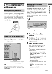
...SPEAKERS (OFF/A/B /A+B) AUTO CAL MIC PHONES VIDEO 3 IN/PORTABLE AV IN VIDEO L AUDIO R MULTI CHANNEL DECODING DISPLAY INPUT MODE INPUT SELECTOR MASTER VOLUME MEMORY/ TUNING ENTER MODE TUNING 2CH A.F.D. If not, use the buttons on the receiver for this system so that the voltage selector is set to ...All index names for inputs and preset stations. • MASTER VOLUME is set to "VOL MIN". • Input is set to turn off the receiver. 2 Hold down ?/1 for 5 seconds. After "CLEARING" appears on the display alternately. 3 Press MEMORY/ENTER. AC power cord CENTER + - ...
...SPEAKERS (OFF/A/B /A+B) AUTO CAL MIC PHONES VIDEO 3 IN/PORTABLE AV IN VIDEO L AUDIO R MULTI CHANNEL DECODING DISPLAY INPUT MODE INPUT SELECTOR MASTER VOLUME MEMORY/ TUNING ENTER MODE TUNING 2CH A.F.D. If not, use the buttons on the receiver for this system so that the voltage selector is set to ...All index names for inputs and preset stations. • MASTER VOLUME is set to "VOL MIN". • Input is set to turn off the receiver. 2 Hold down ?/1 for 5 seconds. After "CLEARING" appears on the display alternately. 3 Press MEMORY/ENTER. AC power cord CENTER + - ...
Operating Instructions
Page 26
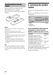
... turn off the speaker output, press SPEAKERS (OFF/A/B/A+B) repeatedly until the "SP A" and "SP B" indicators on the receiver for this operation. ?/1 SPEAKERS (OFF/A/B /A+B) AUTO CAL MIC PHONES VIDEO 3 IN/PORTABLE AV IN VIDEO L AUDIO R MULTI CHANNEL DECODING DISPLAY INPUT MODE INPUT SELECTOR MASTER VOLUME MEMORY/ TUNING ENTER MODE TUNING 2CH A.F.D. To select Light up...
... turn off the speaker output, press SPEAKERS (OFF/A/B/A+B) repeatedly until the "SP A" and "SP B" indicators on the receiver for this operation. ?/1 SPEAKERS (OFF/A/B /A+B) AUTO CAL MIC PHONES VIDEO 3 IN/PORTABLE AV IN VIDEO L AUDIO R MULTI CHANNEL DECODING DISPLAY INPUT MODE INPUT SELECTOR MASTER VOLUME MEMORY/ TUNING ENTER MODE TUNING 2CH A.F.D. To select Light up...


