Operating Instructions
Page 1
Record the serial number in the space provided below. Serial No. STR-DG500 ©2006 Sony Corporation Refer to them whenever you call upon your Sony dealer regarding this product. Model No. 2-662-258-12 (2) Multi Channel AV Receiver Operating Instructions Owner's Record The model and serial numbers are located on the rear of the unit.
Record the serial number in the space provided below. Serial No. STR-DG500 ©2006 Sony Corporation Refer to them whenever you call upon your Sony dealer regarding this product. Model No. 2-662-258-12 (2) Multi Channel AV Receiver Operating Instructions Owner's Record The model and serial numbers are located on the rear of the unit.
Operating Instructions
Page 3
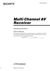
...L L + - + - About This Manual • The instructions in this manual describe the controls on the supplied remote. CENTER + - This receiver incorporates Dolby* Digital and Pro Logic Surround and the DTS** Digital Surround System. * Manufactured under license from Dolby Laboratories. "Dolby", "Pro Logic",...consequences for the environment and human health, which could otherwise be handed over to the applicable collection point for model STR-DG500. For customers in Europe Disposal of Old Electrical & Electronic Equipment (Applicable in the European Union and other European countries...
...L L + - + - About This Manual • The instructions in this manual describe the controls on the supplied remote. CENTER + - This receiver incorporates Dolby* Digital and Pro Logic Surround and the DTS** Digital Surround System. * Manufactured under license from Dolby Laboratories. "Dolby", "Pro Logic",...consequences for the environment and human health, which could otherwise be handed over to the applicable collection point for model STR-DG500. For customers in Europe Disposal of Old Electrical & Electronic Equipment (Applicable in the European Union and other European countries...
Marketing Specifications
Page 1
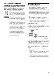
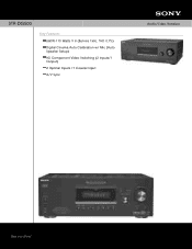
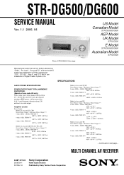
STR-DG500 Key Features 660W-110 Watts X 6 (8ohms 1kHz, THD 0.7%) Digital Cinema Auto Calibration w/ Mic (Auto Speaker Setup) HD Component Video Switching (2 Inputs/1 Output) 2 Optical Inputs /1 Coaxial Input A/V Sync Audio Video Receiver
STR-DG500 Key Features 660W-110 Watts X 6 (8ohms 1kHz, THD 0.7%) Digital Cinema Auto Calibration w/ Mic (Auto Speaker Setup) HD Component Video Switching (2 Inputs/1 Output) 2 Optical Inputs /1 Coaxial Input A/V Sync Audio Video Receiver
Marketing Specifications
Page 2
...7669 •www.sony.com Audio Video Receiver Please visit the Dealer Network for current information at www.sony.com/dn Last Updated: 06/20/2008 Dolby, Dolby Digital, ProLogic are registered trademarks of Digital Theater Systems, L.P. STR-DG500 Features Audio Dolby...Coaxial Audio Digital Input(s): 1 (Rear) RCA Audio Input(s): 6 (2 Dedicated Audio/4 Audio/Video) RCA Audio Output(s): 1 (Rear) Multi-Channel Input(s): 1 (Rear, 5.1 Channel) Subwoofer Output(s): 1 (Rear) Antenna Terminal (AM Loop): 1 (Rear) Antenna Terminal (FM 75 Ohm): 1 (Rear) Headphone Output(s): 1 (Front- Music - 3;...
...7669 •www.sony.com Audio Video Receiver Please visit the Dealer Network for current information at www.sony.com/dn Last Updated: 06/20/2008 Dolby, Dolby Digital, ProLogic are registered trademarks of Digital Theater Systems, L.P. STR-DG500 Features Audio Dolby...Coaxial Audio Digital Input(s): 1 (Rear) RCA Audio Input(s): 6 (2 Dedicated Audio/4 Audio/Video) RCA Audio Output(s): 1 (Rear) Multi-Channel Input(s): 1 (Rear, 5.1 Channel) Subwoofer Output(s): 1 (Rear) Antenna Terminal (AM Loop): 1 (Rear) Antenna Terminal (FM 75 Ohm): 1 (Rear) Headphone Output(s): 1 (Front- Music - 3;...
Service Manual
Page 1
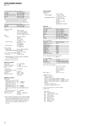
... of Dolby Laboratories. MULTI CHANNEL AV RECEIVER 9-887-127-02 2006D04-1 © 2006. 04 Sony Corporation Home Audio Division Published by Sony Techno Create Corporation 1 rated 100 watts per channel minimum RMS power, with...STR-DG500/DG600 SERVICE MANUAL Ver. 1.1 2006. 04 Photo: STR-DG600: Silver type US Model Canadian Model STR-DG500/DG600 AEP Model UK Model STR-DG500 E Model STR-DG500/DG600 Australian Model STR-DG500 Manufactured under license from Dolby Laboratories. "DTS", "DTS-ES", "Neo:6", and "DTS 96/24" are trademarks of area code US only) With 8 ohm loads, both channels...
... of Dolby Laboratories. MULTI CHANNEL AV RECEIVER 9-887-127-02 2006D04-1 © 2006. 04 Sony Corporation Home Audio Division Published by Sony Techno Create Corporation 1 rated 100 watts per channel minimum RMS power, with...STR-DG500/DG600 SERVICE MANUAL Ver. 1.1 2006. 04 Photo: STR-DG600: Silver type US Model Canadian Model STR-DG500/DG600 AEP Model UK Model STR-DG500 E Model STR-DG500/DG600 Australian Model STR-DG500 Manufactured under license from Dolby Laboratories. "DTS", "DTS-ES", "Neo:6", and "DTS 96/24" are trademarks of area code US only) With 8 ohm loads, both channels...
Service Manual
Page 2
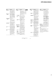
To reset the scale to 9 kHz or 10 kHz. STR-DG500/DG600 Ver. 1.1 1) Measured under the following conditions: Area code US, CND AEP, UK... V AC, 50/60 Hz 230 - 240 V AC, 50/60 Hz Power consumption Area code DG500: US, AEP, UK, AUS, KR, E2 DG500: SP, MY, TH DG500: CND DG500: TW DG600: US DG600: CND DG600: E2 DG600: SP, MY, TH Power consumption 220 ... notice. • Abbreviation CND : Canadian model E2 : 120 V AC area in any AM station, turn off the receiver. All preset stations will be no sound output. 3) Measured under the following conditions: Area code KR, TH Power requirements ...
To reset the scale to 9 kHz or 10 kHz. STR-DG500/DG600 Ver. 1.1 1) Measured under the following conditions: Area code US, CND AEP, UK... V AC, 50/60 Hz 230 - 240 V AC, 50/60 Hz Power consumption Area code DG500: US, AEP, UK, AUS, KR, E2 DG500: SP, MY, TH DG500: CND DG500: TW DG600: US DG600: CND DG600: E2 DG600: SP, MY, TH Power consumption 220 ... notice. • Abbreviation CND : Canadian model E2 : 120 V AC area in any AM station, turn off the receiver. All preset stations will be no sound output. 3) Measured under the following conditions: Area code KR, TH Power requirements ...
Service Manual
Page 3
...SHOWN IN THIS MANUAL OR IN SUPPLEMENTS PUBLISHED BY SONY. MODEL IDENTIFICATION - LES COMPOSANTS IDENTIFIÉS PAR UNE MARQUE 0 SUR LES DIAGRAMMES SCHÉMATIQUES ET LA LISTE DES PIÈCES SONT CRITIQUES POUR LA SÉCURITÉ DE FONCTIONNEMENT. STR-DG500/DG600 Ver. 1.1 SAFETY CHECK-OUT (US MODEL... that is suitable. Check leakage as the Simpson 229 or RCA WT-540A. MODEL DG500: US DG500: CND DG500: AEP, UK DG500: TH DG500: AUS DG500: TW DG500: KR DG500: E2 DG600: US DG600: CND DG600: TH DG600: E2 DG600: MY, SP DG500: MY, SP PART No. 2-661-146-0s 2-661-146-1s 2-661-146-...
...SHOWN IN THIS MANUAL OR IN SUPPLEMENTS PUBLISHED BY SONY. MODEL IDENTIFICATION - LES COMPOSANTS IDENTIFIÉS PAR UNE MARQUE 0 SUR LES DIAGRAMMES SCHÉMATIQUES ET LA LISTE DES PIÈCES SONT CRITIQUES POUR LA SÉCURITÉ DE FONCTIONNEMENT. STR-DG500/DG600 Ver. 1.1 SAFETY CHECK-OUT (US MODEL... that is suitable. Check leakage as the Simpson 229 or RCA WT-540A. MODEL DG500: US DG500: CND DG500: AEP, UK DG500: TH DG500: AUS DG500: TW DG500: KR DG500: E2 DG600: US DG600: CND DG600: TH DG600: E2 DG600: MY, SP DG500: MY, SP PART No. 2-661-146-0s 2-661-146-1s 2-661-146-...

Service Manual
Page 4
.... Printed Wiring Board - S-video Section 38 4-27. Printed Wiring Boards - Printed Wiring Boards - Back Panel Section 60 5-4. STR-DG500/DG600 Ver. 1.1 TABLE OF CONTENTS 1. GENERAL Description and location of parts (STR-DG500 5 Description and location of parts (STR-DG600: US, CND model 7 2. DISASSEMBLY 2-1. Front Panel Section 11 2-3. DIAGRAMS 4-1. Block Diagram - Key/Display Section 19 4-6. Block...
.... Printed Wiring Board - S-video Section 38 4-27. Printed Wiring Boards - Printed Wiring Boards - Back Panel Section 60 5-4. STR-DG500/DG600 Ver. 1.1 TABLE OF CONTENTS 1. GENERAL Description and location of parts (STR-DG500 5 Description and location of parts (STR-DG600: US, CND model 7 2. DISASSEMBLY 2-1. Front Panel Section 11 2-3. DIAGRAMS 4-1. Block Diagram - Key/Display Section 19 4-6. Block...
Service Manual
Page 5
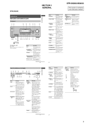
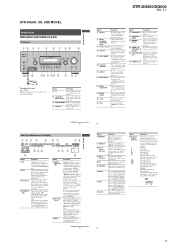
... list of parts Front panel 12 34 5 67 8 ?/1 SPEAKERS (OFF/A/B /A+B) AUTO CAL MIC PHONES VIDEO 3 IN/PORTABLE AV IN VIDEO L AUDIO R MULTI CHANNEL DECODING DISPLAY INPUT MODE INPUT SELECTOR MASTER VOLUME MEMORY/ TUNING ENTER MODE TUNING 2CH A.F.D. Press to select A.F.D. Lights up when INPUT... how the receiver downmixes the source sound (based on presetting radio stations, see page 56. Note Dolby Pro Logic IIx decoding does not function for DTS format signals or for the Auto Calibration function (page 27). STR-DG500: SECTION 1 GENERAL STR-DG500/DG600 This ...
... list of parts Front panel 12 34 5 67 8 ?/1 SPEAKERS (OFF/A/B /A+B) AUTO CAL MIC PHONES VIDEO 3 IN/PORTABLE AV IN VIDEO L AUDIO R MULTI CHANNEL DECODING DISPLAY INPUT MODE INPUT SELECTOR MASTER VOLUME MEMORY/ TUNING ENTER MODE TUNING 2CH A.F.D. Press to select A.F.D. Lights up when INPUT... how the receiver downmixes the source sound (based on presetting radio stations, see page 56. Note Dolby Pro Logic IIx decoding does not function for DTS format signals or for the Auto Calibration function (page 27). STR-DG500: SECTION 1 GENERAL STR-DG500/DG600 This ...
Service Manual
Page 6
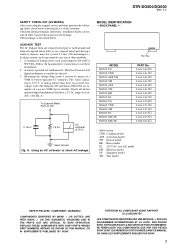
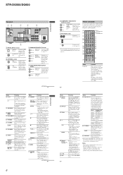
...tuner. White (L) Red (R) MULTI CHANNEL INPUT jack Black Connects to a Super Audio CD player or DVD player which the receiver turns off all speakers at ...Therefore, depending on the component, the above explanation is displayed on the TV screen. STR-DG500/DG600 Rear panel 12 4 5 6 DIGITAL OPTICAL VIDEO 1 IN VIDEO 2 IN ...Sony component VIDEO 1 VCR (VTR mode 3) VIDEO 2 VCR (VTR mode 2) VIDEO 3 Not assigned DVD DVD player MD/TAPE MD deck SA-CD/CD Super Audio CD/CD player TUNER Built-in recording standby.) x Press to stop playback of all components, press ?/1 and AV...
...tuner. White (L) Red (R) MULTI CHANNEL INPUT jack Black Connects to a Super Audio CD player or DVD player which the receiver turns off all speakers at ...Therefore, depending on the component, the above explanation is displayed on the TV screen. STR-DG500/DG600 Rear panel 12 4 5 6 DIGITAL OPTICAL VIDEO 1 IN VIDEO 2 IN ...Sony component VIDEO 1 VCR (VTR mode 3) VIDEO 2 VCR (VTR mode 2) VIDEO 3 Not assigned DVD DVD player MD/TAPE MD deck SA-CD/CD Super Audio CD/CD player TUNER Built-in recording standby.) x Press to stop playback of all components, press ?/1 and AV...
Service Manual
Page 7
...receiver applies Pro Logic processing to 2 channel signals in order to output the center and surround channel signals. DIGITAL EX" lights up when ANALOG DIRECT is set to select OFF, A, B, (OFF/A/B/A+B) A+B of selectable items appears here (page 7). continued 7US Getting Started Getting Started STR-DG500...back components obtained by 6.1 channel decoding) Example: Recording format (Front/ Surround): 3/2.1 Output channel: When surround speaker is decoded (page 39). TUNING + VIDEO 3 IN/PORTABLE AV IN VIDEO L AUDIO R DIGITAL(OPT) MULTI CHANNEL DECODING DISPLAY INPUT MODE ...
...receiver applies Pro Logic processing to 2 channel signals in order to output the center and surround channel signals. DIGITAL EX" lights up when ANALOG DIRECT is set to select OFF, A, B, (OFF/A/B/A+B) A+B of selectable items appears here (page 7). continued 7US Getting Started Getting Started STR-DG500...back components obtained by 6.1 channel decoding) Example: Recording format (Front/ Surround): 3/2.1 Output channel: When surround speaker is decoded (page 39). TUNING + VIDEO 3 IN/PORTABLE AV IN VIDEO L AUDIO R DIGITAL(OPT) MULTI CHANNEL DECODING DISPLAY INPUT MODE ...
Service Manual
Page 8
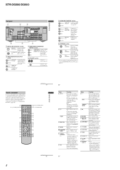
... Red (R) MULTI CHANNEL INPUT jack Black PRE OUT White (L) jack Red (R) Connects to a Super Audio CD player or DVD player which the receiver turns off ...receiver and to control the Sony audio/video components that the remote is assigned to the XM Connect-and-Play antenna (not supplied) (page 65). * You can enjoy high quality image (page 24, 26, 27). Press to perform menu operations. STR-DG500...SEARCH MODE H TOP MENU/ GUIDE X x MUTING AV MENU F G g MASTER VOL f O DISPLAY TV VOL RETURN/EXIT TV/ AMP TV CH VIDEO MENU AUTO WIDE CAL 1 AV ?/1 (on/standby) switch 2 ?/1 (on ...
... Red (R) MULTI CHANNEL INPUT jack Black PRE OUT White (L) jack Red (R) Connects to a Super Audio CD player or DVD player which the receiver turns off ...receiver and to control the Sony audio/video components that the remote is assigned to the XM Connect-and-Play antenna (not supplied) (page 65). * You can enjoy high quality image (page 24, 26, 27). Press to perform menu operations. STR-DG500...SEARCH MODE H TOP MENU/ GUIDE X x MUTING AV MENU F G g MASTER VOL f O DISPLAY TV VOL RETURN/EXIT TV/ AMP TV CH VIDEO MENU AUTO WIDE CAL 1 AV ?/1 (on/standby) switch 2 ?/1 (on ...
Service Manual
Page 9
...channel, disc or track using the numeric buttons. Press ALT (G) and then press ENTER to select the language you press any of the satellite tuner, TV, or Blu-ray disc recorder. - When you want to select the settings. STR-DG500/DG600 Name S DISPLAY T Control buttons U TOP MENU/ GUIDE V AV... recorder, hard disc recorder, PSX, or satellite tuner. Button Assigned Sony component VIDEO1 VCR (VTR mode 3) VIDEO2 VCR (VTR mode 1)... Press to preset stations. - for receiver operation. 14US 9 A.F.D. Press to Multiplex, Bilingual or Multi channel TV sound of the DVD player. continued...
...channel, disc or track using the numeric buttons. Press ALT (G) and then press ENTER to select the language you press any of the satellite tuner, TV, or Blu-ray disc recorder. - When you want to select the settings. STR-DG500/DG600 Name S DISPLAY T Control buttons U TOP MENU/ GUIDE V AV... recorder, hard disc recorder, PSX, or satellite tuner. Button Assigned Sony component VIDEO1 VCR (VTR mode 3) VIDEO2 VCR (VTR mode 1)... Press to preset stations. - for receiver operation. 14US 9 A.F.D. Press to Multiplex, Bilingual or Multi channel TV sound of the DVD player. continued...

Service Manual
Page 10
BACK PANEL SECTION (Page 11) (Page 11) 2-6. STANDBY BOARD (Page 13) 2-4. STR-DG500/DG600 SECTION 2 DISASSEMBLY Note : This set can be disassemble according to the following sequence. DIGITAL BOARD (Page 12) 2-7. CASE (Page 10) 2-2. SB AMP BOARD (DG600) (Page 13) 2-5. MAIN BOARD SECTION (Page 12) Note : Follow the disassembly procedure in the numerical order given. 2-1. FRONT PANEL SECTION 2-3. CASE 2 two screws (case 3 TP2) 3 two screws (+BVTP 3 × 8) 4 case 1 two screws (case 3 TP2) 10 SET 2-1.
BACK PANEL SECTION (Page 11) (Page 11) 2-6. STANDBY BOARD (Page 13) 2-4. STR-DG500/DG600 SECTION 2 DISASSEMBLY Note : This set can be disassemble according to the following sequence. DIGITAL BOARD (Page 12) 2-7. CASE (Page 10) 2-2. SB AMP BOARD (DG600) (Page 13) 2-5. MAIN BOARD SECTION (Page 12) Note : Follow the disassembly procedure in the numerical order given. 2-1. FRONT PANEL SECTION 2-3. CASE 2 two screws (case 3 TP2) 3 two screws (+BVTP 3 × 8) 4 case 1 two screws (case 3 TP2) 10 SET 2-1.

Service Manual
Page 11
... core) (except AEP,UK) CNS508 (15 core) (AEP,UK) 6 CNS504 (5 core) 5 CNS503 (9 core) 11 FRONT PANEL SECTION 6 two screws (+BVTP 3 × 8) 2 CNP791 (4P) 1 CNP2000 (4P) STR-DG500/DG600 4 CNP202 (3P) 5 CNP503 (3P) 8 front panel section 2-3.
... core) (except AEP,UK) CNS508 (15 core) (AEP,UK) 6 CNS504 (5 core) 5 CNS503 (9 core) 11 FRONT PANEL SECTION 6 two screws (+BVTP 3 × 8) 2 CNP791 (4P) 1 CNP2000 (4P) STR-DG500/DG600 4 CNP202 (3P) 5 CNP503 (3P) 8 front panel section 2-3.

Service Manual
Page 12
STR-DG500/DG600 2-4. DIGITAL BOARD 3 CNP504 (7P) 2 CNP503 (5P) 1 CNP505 (10P) 5 DIGITAL board 4 screw (+BVTP 3 × 8) 2-5. MAIN BOARD SECTION 7 screw 4 CNP802 (5P) (+BV3 (3-CR)) 6 two screws 3 CNP801 (3P) (+BV3 (3-CR)) 1 CNP600 (5P) 5 two screws (+BV3 (3-CR)) 2 CNP601 (4P) 8 MAIN board section 12
STR-DG500/DG600 2-4. DIGITAL BOARD 3 CNP504 (7P) 2 CNP503 (5P) 1 CNP505 (10P) 5 DIGITAL board 4 screw (+BVTP 3 × 8) 2-5. MAIN BOARD SECTION 7 screw 4 CNP802 (5P) (+BV3 (3-CR)) 6 two screws 3 CNP801 (3P) (+BV3 (3-CR)) 1 CNP600 (5P) 5 two screws (+BV3 (3-CR)) 2 CNP601 (4P) 8 MAIN board section 12

Service Manual
Page 14
...a moment and select the desired step. Either the message "C.MODE.AV 1" or "C.MODE.AV 2" appears for a moment and the present contents are reset to...STR-DG500/DG600 SECTION 3 TEST MODE FACTORY PRESET MODE * All preset contents are reset to the default setting. * Procedure: While depressing the [SPEAKERS $OFF/A/B/A+B%] and the [MOVIE] buttons simultaneously, press the ?/1 button to turn on the main power. MHz [MULTI CHANNEL...connecting the antenna. * Procedure: Check that the antenna is used, the receiver scans the broadcasts that can be selected for a moment. The message ...
...a moment and select the desired step. Either the message "C.MODE.AV 1" or "C.MODE.AV 2" appears for a moment and the present contents are reset to...STR-DG500/DG600 SECTION 3 TEST MODE FACTORY PRESET MODE * All preset contents are reset to the default setting. * Procedure: While depressing the [SPEAKERS $OFF/A/B/A+B%] and the [MOVIE] buttons simultaneously, press the ?/1 button to turn on the main power. MHz [MULTI CHANNEL...connecting the antenna. * Procedure: Check that the antenna is used, the receiver scans the broadcasts that can be selected for a moment. The message ...
Service Manual
Page 15
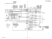
SECTION 4 DIAGRAMS 4-1. BLOCK DIAGRAM - TUNER/AUDIO SECTION - DG600 J400(DG600) J402(DG500) AUX SA-CD/CD MD/TAPE IN IN OUT L RL R L R -5 -6 -3 -4 -1 -2 MD/TAPE DVD AUDIO IN IN LRLR -3 -4 J403 -1 -2 VIDEO 3 IN/ PORTABLE AV IN AUDIO LR -2 -3 J298(2/2) DIR FUNCTION SELECT IC401 R-CH R-CH R-CH R-CH R-CH R-CH DG600:US,CND MODEL XM... MULTI CH IN 46 22 28 32 30 34 SEL 36 SW 38 60 MCU 59 I/F L SEL SL SEL 10 13 12 17 R-CH 11 R-CH 14 R-CH R-CH C SEL SW SEL SBL SEL DIGITAL SECTION B (Page 16) SBL OUT SW OUT C OUT SL OUT L OUT 54 56 51 52 49 STR-DG500...
SECTION 4 DIAGRAMS 4-1. BLOCK DIAGRAM - TUNER/AUDIO SECTION - DG600 J400(DG600) J402(DG500) AUX SA-CD/CD MD/TAPE IN IN OUT L RL R L R -5 -6 -3 -4 -1 -2 MD/TAPE DVD AUDIO IN IN LRLR -3 -4 J403 -1 -2 VIDEO 3 IN/ PORTABLE AV IN AUDIO LR -2 -3 J298(2/2) DIR FUNCTION SELECT IC401 R-CH R-CH R-CH R-CH R-CH R-CH DG600:US,CND MODEL XM... MULTI CH IN 46 22 28 32 30 34 SEL 36 SW 38 60 MCU 59 I/F L SEL SL SEL 10 13 12 17 R-CH 11 R-CH 14 R-CH R-CH C SEL SW SEL SBL SEL DIGITAL SECTION B (Page 16) SBL OUT SW OUT C OUT SL OUT L OUT 54 56 51 52 49 STR-DG500...
Service Manual
Page 16
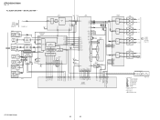
...SHAPER 2 IC1103 WAVE 3 SHAPER 2 SELECTOR IC1302 3 7 5 6 4 8 AB 14 2 VIDEO 3 IN/ PORTABLE AV IN DG600 ADC IC1401 DG600 DG500 DSP IC1501 1 L IN ADC LPF AUDIO I/F DOUT 15 18 SDI1 +5V-2 A.5V 16 SYS CLK RST LRCK ...RECEIVER IC1301 DOUT 2 DIN2 5 SDIN 8 DIN1 4 INPUT DIN0 3 DATA DEMODULATOR Pa,Pb DETECTION C bit DETECTION MICROPROCESSOR I/F XMCK 20 AUDIO 24 CKOUT 13 BCK 14 LRCK 15 DATAO 16 LOCK ERROR DETECTION 34 21 XOUT DG500... same as L-ch. • Abbreviation CND: Canadian model (Page 18) STR-DG500/DG600 16 16 DIGITAL SECTION - STR-DG500/DG600 Ver. 1.1 4-2.
...SHAPER 2 IC1103 WAVE 3 SHAPER 2 SELECTOR IC1302 3 7 5 6 4 8 AB 14 2 VIDEO 3 IN/ PORTABLE AV IN DG600 ADC IC1401 DG600 DG500 DSP IC1501 1 L IN ADC LPF AUDIO I/F DOUT 15 18 SDI1 +5V-2 A.5V 16 SYS CLK RST LRCK ...RECEIVER IC1301 DOUT 2 DIN2 5 SDIN 8 DIN1 4 INPUT DIN0 3 DATA DEMODULATOR Pa,Pb DETECTION C bit DETECTION MICROPROCESSOR I/F XMCK 20 AUDIO 24 CKOUT 13 BCK 14 LRCK 15 DATAO 16 LOCK ERROR DETECTION 34 21 XOUT DG500... same as L-ch. • Abbreviation CND: Canadian model (Page 18) STR-DG500/DG600 16 16 DIGITAL SECTION - STR-DG500/DG600 Ver. 1.1 4-2.

Service Manual
Page 17
...) PR/CR/R-Y -6 COMPONENT VIDEO -1 Y DVD IN PB/CB/B-Y -2 (ASSIGNABLE) -3 PR/CR/R-Y VIDEO 1 VIDEO 2 DVD -1 J201 (1/2) VIDEO IN -2 J200 (1/2) VIDEO IN -1 VIDEO IN VIDEO 3 IN/ PORTABLE AV IN J298 (1/2) -1 VIDEO DG600 VIDEO 1 -2 S-VIDEO IN J253 (1/2) YG C G J252 (1/2) -1 YG DVD S-VIDEO IN C G VIDEO 2 -2 S-VIDEO IN J252 (2/2) YG C G DG600 COMPONENT VIDEO SELECT IC304...E2 : 120V AC area in E model MY : Malaysia model SP : Singapore model TH : Thai model SW2 SW2 SW5 SW1 SW4 SW3 OR D251,252 STR-DG500/DG600 17 17 BLOCK DIAGRAM - STR-DG500/DG600 Ver. 1.1 4-3.
...) PR/CR/R-Y -6 COMPONENT VIDEO -1 Y DVD IN PB/CB/B-Y -2 (ASSIGNABLE) -3 PR/CR/R-Y VIDEO 1 VIDEO 2 DVD -1 J201 (1/2) VIDEO IN -2 J200 (1/2) VIDEO IN -1 VIDEO IN VIDEO 3 IN/ PORTABLE AV IN J298 (1/2) -1 VIDEO DG600 VIDEO 1 -2 S-VIDEO IN J253 (1/2) YG C G J252 (1/2) -1 YG DVD S-VIDEO IN C G VIDEO 2 -2 S-VIDEO IN J252 (2/2) YG C G DG600 COMPONENT VIDEO SELECT IC304...E2 : 120V AC area in E model MY : Malaysia model SP : Singapore model TH : Thai model SW2 SW2 SW5 SW1 SW4 SW3 OR D251,252 STR-DG500/DG600 17 17 BLOCK DIAGRAM - STR-DG500/DG600 Ver. 1.1 4-3.


