
Limited Warranty (U.S. Only)
Page 1
...: To locate the servicer or dealer nearest you . 4-557-173-02 General Stereo/Hifi Components/Tape Decks ® CD Players/Mini Disc Players/Audio Systems Hifi Audio LIMITED WARRANTY Sony Electronics Inc. ("Sony") warrants this Product is determined to be presented to any part of a service...FOR A PARTICULAR PURPOSE ON THIS PRODUCT IS LIMITED IN DURATION TO THE DURATION OF THIS WARRANTY. This warranty does not cover customer instruction, installation, set up adjustments or signal reception problems. This warranty does not cover cosmetic damage or damage due to acts of God...
...: To locate the servicer or dealer nearest you . 4-557-173-02 General Stereo/Hifi Components/Tape Decks ® CD Players/Mini Disc Players/Audio Systems Hifi Audio LIMITED WARRANTY Sony Electronics Inc. ("Sony") warrants this Product is determined to be presented to any part of a service...FOR A PARTICULAR PURPOSE ON THIS PRODUCT IS LIMITED IN DURATION TO THE DURATION OF THIS WARRANTY. This warranty does not cover customer instruction, installation, set up adjustments or signal reception problems. This warranty does not cover cosmetic damage or damage due to acts of God...
Service Manual
Page 3
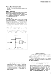
...BY SONY. Follow the manufacturers' instructions to check AC leakage. Measuring the voltage drop across a resistor by means of a passive VOM that is suitable. The "limit" indication is suitable for AC leakage. Nearly all exposed metal parts to any one of a tantalum capacitor may be dam- STR-DB870/DB1070 ...SAFETY-RELATED COMPONENT WARNING!! ATTENTION AU COMPOSANT AYANT RAPPORT À LA SÉCURITÉ! NE REMPLACER CES COMPOSANTS QUE PAR DES PIÈCES SONY DONT LES NUMÉROS SONT DONNÉS DANS CE ...
...BY SONY. Follow the manufacturers' instructions to check AC leakage. Measuring the voltage drop across a resistor by means of a passive VOM that is suitable. The "limit" indication is suitable for AC leakage. Nearly all exposed metal parts to any one of a tantalum capacitor may be dam- STR-DB870/DB1070 ...SAFETY-RELATED COMPONENT WARNING!! ATTENTION AU COMPOSANT AYANT RAPPORT À LA SÉCURITÉ! NE REMPLACER CES COMPOSANTS QUE PAR DES PIÈCES SONY DONT LES NUMÉROS SONT DONNÉS DANS CE ...
Service Manual
Page 6
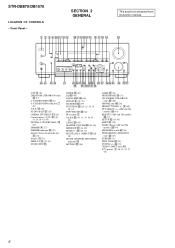
...(32) DISPLAY 3 (27, 41) DOOR OPEN wg ENTER wh (43) EQ e; (36) EQUALIZER ef (36) FM/AM 6 (38, 39) FM MODE r; (39) FUNCTION wd (24, 25, 38, 39, 40, 43) INPUT MODE wf (26) IR receptor ... 30) MULTI CHANNEL DECODING indicator qd MUTING ws (26) NAME ed (43) NIGHT MODE ql (31) ON SCREEN (STR-DB1070 only) rd (10) PHONES jack rg (26) PRESET TUNING +/- 9 (40) PTY SELECT +/- (AEP and UK...45678 9 0 qa qsqdqf qg qh qj qk ql This section is extracted from instruction manual. wk wj whwg wf wd wswa el eh efedea wl 2CH qg (30) 2ND ROOM (STR-DB1070 only) eg (27) 6.1CH DECODING 0 (31) 6.1CH DECODING indicator 7 ...
...(32) DISPLAY 3 (27, 41) DOOR OPEN wg ENTER wh (43) EQ e; (36) EQUALIZER ef (36) FM/AM 6 (38, 39) FM MODE r; (39) FUNCTION wd (24, 25, 38, 39, 40, 43) INPUT MODE wf (26) IR receptor ... 30) MULTI CHANNEL DECODING indicator qd MUTING ws (26) NAME ed (43) NIGHT MODE ql (31) ON SCREEN (STR-DB1070 only) rd (10) PHONES jack rg (26) PRESET TUNING +/- 9 (40) PTY SELECT +/- (AEP and UK...45678 9 0 qa qsqdqf qg qh qj qk ql This section is extracted from instruction manual. wk wj whwg wf wd wswa el eh efedea wl 2CH qg (30) 2ND ROOM (STR-DB1070 only) eg (27) 6.1CH DECODING 0 (31) 6.1CH DECODING indicator 7 ...
Operating Instructions (primary manual)
Page 1
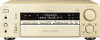
Model No. STR-DB1070 STR-DB870 © 2001 Sony Corporation Refer to them whenever you call upon your Sony dealer regarding this product. 4-235-985-14(1) FM Stereo FM-AM Receiver Operating Instructions Owner's Record The model and serial numbers are located on the rear panel. Serial No. Record the serial number in the space provided below.
Model No. STR-DB1070 STR-DB870 © 2001 Sony Corporation Refer to them whenever you call upon your Sony dealer regarding this product. 4-235-985-14(1) FM Stereo FM-AM Receiver Operating Instructions Owner's Record The model and serial numbers are located on the rear panel. Serial No. Record the serial number in the space provided below.
Operating Instructions (primary manual)
Page 2
... of the NEC that to rain or moisture. This receiver incorporates Dolby* Digital and Pro Logic Surround and the ... trademarks of important operating and maintenance (servicing) instructions in accordance with the limits for energy efficiency...been tested and found to comply with the instructions, may be connected to the grounding system of...Systems, Inc. Increase the separation between the equipment and receiver. - Do not install the appliance in a confined... or television reception, which the receiver is a U.S. Reorient or relocate the receiving antenna. - Note to CATV ...
... of the NEC that to rain or moisture. This receiver incorporates Dolby* Digital and Pro Logic Surround and the ... trademarks of important operating and maintenance (servicing) instructions in accordance with the limits for energy efficiency...been tested and found to comply with the instructions, may be connected to the grounding system of...Systems, Inc. Increase the separation between the equipment and receiver. - Do not install the appliance in a confined... or television reception, which the receiver is a U.S. Reorient or relocate the receiving antenna. - Note to CATV ...
Operating Instructions (primary manual)
Page 4
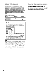
... BACK PRE OUT IMPEDANCE SELECTOR 4 Ω 8 Ω - Tip The instructions in the text, for models STR-DB1070 and STR-DB870. About This Manual The instructions in this manual are not available. 4 For details on the lower portion of the receiver you purchased is used for example, "STR-DB1070 only". Check your remote, see the illustration below). KERS USE...
... BACK PRE OUT IMPEDANCE SELECTOR 4 Ω 8 Ω - Tip The instructions in the text, for models STR-DB1070 and STR-DB870. About This Manual The instructions in this manual are not available. 4 For details on the lower portion of the receiver you purchased is used for example, "STR-DB1070 only". Check your remote, see the illustration below). KERS USE...

Operating Instructions (primary manual)
Page 12
... OUT jack is not possible to record analog signals to the components connected to the operating instructions supplied with your CD or SACD player, connect the CD or SACD player's digital output directly to the receiver's digital output jack. MD or DAT deck DIGITAL OPTICAL IN OUT INPUT OUTPUT LINE LINE L R...S-VIDEO S-VIDEO IN IN VIDEO VIDEO OUT VIDEO IN VIDEO S-VIDEO S-VIDEO OUT IN VIDEO VIDEO MD/DAT OPTICAL IN MD/DAT OPTICAL OUT U FM CONTROL 75Ω A1 MONITOR COAXIAL AUDIO IN L AUDIO IN AUDIO OUT AUDIO IN AUDIO OUT AUDIO IN MONITOR OUT L COM DVD/LD COAXIAL ...
... OUT jack is not possible to record analog signals to the components connected to the operating instructions supplied with your CD or SACD player, connect the CD or SACD player's digital output directly to the receiver's digital output jack. MD or DAT deck DIGITAL OPTICAL IN OUT INPUT OUTPUT LINE LINE L R...S-VIDEO S-VIDEO IN IN VIDEO VIDEO OUT VIDEO IN VIDEO S-VIDEO S-VIDEO OUT IN VIDEO VIDEO MD/DAT OPTICAL IN MD/DAT OPTICAL OUT U FM CONTROL 75Ω A1 MONITOR COAXIAL AUDIO IN L AUDIO IN AUDIO OUT AUDIO IN AUDIO OUT AUDIO IN MONITOR OUT L COM DVD/LD COAXIAL ...
Operating Instructions (primary manual)
Page 13
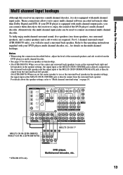
...instructions supplied with multi channel input jacks. DVD player, Multichannel decoder, etc. 13 For 6.1 channel surround sound (STR-DB1070 only), you set the center speaker to use as the surround back speaker in formats other than Dolby Digital and DTS. Hooking Up the Components Multi channel input hookups Although this receiver... VIDEO S-VIDEO IN VIDEO OUT VIDEO IN VIDEO S-VIDEO S-VIDEO OUT IN VIDEO VIDEO MD/DAT OPTICAL IN MD/DAT OPTICAL OUT U FM CONTROL 75Ω A1 MONITOR COAXIAL AUDIO IN L AUDIO IN AUDIO OUT AUDIO IN AUDIO OUT AUDIO IN MONITOR OUT L COM DVD/LD...
...instructions supplied with multi channel input jacks. DVD player, Multichannel decoder, etc. 13 For 6.1 channel surround sound (STR-DB1070 only), you set the center speaker to use as the surround back speaker in formats other than Dolby Digital and DTS. Hooking Up the Components Multi channel input hookups Although this receiver... VIDEO S-VIDEO IN VIDEO OUT VIDEO IN VIDEO S-VIDEO S-VIDEO OUT IN VIDEO VIDEO MD/DAT OPTICAL IN MD/DAT OPTICAL OUT U FM CONTROL 75Ω A1 MONITOR COAXIAL AUDIO IN L AUDIO IN AUDIO OUT AUDIO IN AUDIO OUT AUDIO IN MONITOR OUT L COM DVD/LD...
Operating Instructions (primary manual)
Page 14
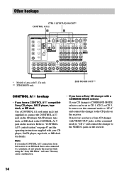
...VIDEO S-VIDEO OUT IN VIDEO VIDEO MD/DAT OPTICAL IN MD/DAT OPTICAL OUT U FM CONTROL 75Ω A1 MONITOR COAXIAL AUDIO IN L AUDIO IN AUDIO OUT AUDIO IN ...STR-DB1070 only. 2ND ROOM OUT** CONTROL A1 hookup • If you have a Sony CD changer with VIDEO OUT jacks, set the command mode to "CD 1" and connect the changer to the CD jacks on the receiver. Note If you have a CONTROL A1 compatible Sony... the receiver to an MD deck that is also connected to the VIDEO 2 jacks on the receiver. Refer to "CONTROL A1 control system" on page 47 and the operating instructions supplied ...
...VIDEO S-VIDEO OUT IN VIDEO VIDEO MD/DAT OPTICAL IN MD/DAT OPTICAL OUT U FM CONTROL 75Ω A1 MONITOR COAXIAL AUDIO IN L AUDIO IN AUDIO OUT AUDIO IN ...STR-DB1070 only. 2ND ROOM OUT** CONTROL A1 hookup • If you have a Sony CD changer with VIDEO OUT jacks, set the command mode to "CD 1" and connect the changer to the CD jacks on the receiver. Note If you have a CONTROL A1 compatible Sony... the receiver to an MD deck that is also connected to the VIDEO 2 jacks on the receiver. Refer to "CONTROL A1 control system" on page 47 and the operating instructions supplied ...

Operating Instructions (primary manual)
Page 15
..., monitor, VCR, etc., for details. If not, use a screwdriver to set to a stereo amplifier located in another room (see page 27). VOLTAGE SELECTOR 220V 240V 120V continued DVD player... CONTROL S hookup (Models of area code U, CA only) If you have a S-LINK CONTROL Scompatible Sony TV, satellite tuner, monitor, DVD player or VCR, use an audio/video/ control S connecting cord ...or OUT (for VCR, etc.) jack on the receiver to a wall outlet. Note Refer to the operating instructions supplied with your TV. 2ND ROOM hookup (STR-DB1070 only) You can control from the supplied audio/ ...
..., monitor, VCR, etc., for details. If not, use a screwdriver to set to a stereo amplifier located in another room (see page 27). VOLTAGE SELECTOR 220V 240V 120V continued DVD player... CONTROL S hookup (Models of area code U, CA only) If you have a S-LINK CONTROL Scompatible Sony TV, satellite tuner, monitor, DVD player or VCR, use an audio/video/ control S connecting cord ...or OUT (for VCR, etc.) jack on the receiver to a wall outlet. Note Refer to the operating instructions supplied with your TV. 2ND ROOM hookup (STR-DB1070 only) You can control from the supplied audio/ ...

Operating Instructions (primary manual)
Page 18
... nominal impedance between 4 and 8 ohms to the PRE OUT FRONT L and R jacks. 2ND ROOM hookup (STR-DB1070 area code U, CA only) You can use the PRE OUT jacks. Check the operating instructions supplied with a nominal impedance of preset stations and program sources) are cleared. • All SET UP parameters ... factory settings. • The sound field memorized for the 2nd room is connected, set the IMPEDANCE SELECTOR to turn the power off the receiver. 2 Hold down ?/1 for your speakers if you want to either of the speaker terminals. However, even if one speaker within this range...
... nominal impedance between 4 and 8 ohms to the PRE OUT FRONT L and R jacks. 2ND ROOM hookup (STR-DB1070 area code U, CA only) You can use the PRE OUT jacks. Check the operating instructions supplied with a nominal impedance of preset stations and program sources) are cleared. • All SET UP parameters ... factory settings. • The sound field memorized for the 2nd room is connected, set the IMPEDANCE SELECTOR to turn the power off the receiver. 2 Hold down ?/1 for your speakers if you want to either of the speaker terminals. However, even if one speaker within this range...

Operating Instructions (primary manual)
Page 27
Use the remote to the operating instructions supplied with the remote. Refer to adjust the volume in the ... The 2nd room speaker setting is displayed for output to a stereo amplifier or speakers*1 in another room (STR-DB1070 only) •• SPEAKERS 2ND ROOM OUT AUDIO IN Stereo amplifier SPEAKERS Press 2ND ROOM repeatedly to select the analog audio ...set to MULTI 1 or 2 DIRECT. • Only signals from components connected to the analog input jacks are turned off the receiver. DIRECT is the same as follows: SOURCE*2 t TAPE t MD/DAT t CD/SACD t TUNER *2 The audio signals of...
Use the remote to the operating instructions supplied with the remote. Refer to adjust the volume in the ... The 2nd room speaker setting is displayed for output to a stereo amplifier or speakers*1 in another room (STR-DB1070 only) •• SPEAKERS 2ND ROOM OUT AUDIO IN Stereo amplifier SPEAKERS Press 2ND ROOM repeatedly to select the analog audio ...set to MULTI 1 or 2 DIRECT. • Only signals from components connected to the analog input jacks are turned off the receiver. DIRECT is the same as follows: SOURCE*2 t TAPE t MD/DAT t CD/SACD t TUNER *2 The audio signals of...
Operating Instructions (primary manual)
Page 38
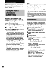
... entered the right frequency. For details on the buttons used in your new area. • For details on RDS, see the operating instructions for stations broadcasting the same program, then stores only the one , see "Presetting radio stations" on page 40. 1 Press ?/1 to turn off ...stations one by their Program Service name, then assigned a 2-character preset code. TUNING. 4 Press the numeric buttons to select the FM or AM band. 3 Press D. Receiving Broadcasts Before receiving broadcasts, make sure you have to enter the last "0" when the tuning scale is set to 10 kHz.) 1 b3 b5 ...
... entered the right frequency. For details on the buttons used in your new area. • For details on RDS, see the operating instructions for stations broadcasting the same program, then stores only the one , see "Presetting radio stations" on page 40. 1 Press ?/1 to turn off ...stations one by their Program Service name, then assigned a 2-character preset code. TUNING. 4 Press the numeric buttons to select the FM or AM band. 3 Press D. Receiving Broadcasts Before receiving broadcasts, make sure you have to enter the last "0" when the tuning scale is set to 10 kHz.) 1 b3 b5 ...
Operating Instructions (primary manual)
Page 40
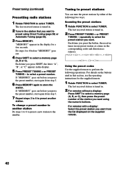
...page (A, B, or C), then press the preset number of the following operations. The last received station is tuned in this section, see the operating instructions for a few seconds. For details on the supplied remote. 40 The last received station is tuned in the station that you press the button, the... receiver tunes in one preset station at a time, in the display. 5 Press PRESET...
...page (A, B, or C), then press the preset number of the following operations. The last received station is tuned in this section, see the operating instructions for a few seconds. For details on the supplied remote. 40 The last received station is tuned in the station that you press the button, the... receiver tunes in one preset station at a time, in the display. 5 Press PRESET...

Operating Instructions (primary manual)
Page 43
... to jacks meant for another station or program source. This function is selected. If you are not familiar with how to tune in the receiver's display when a station or program source is useful for distinguishing components of an RDS station. To index a program source Select the program ...Select the component to be recorded. 2 Prepare the component for playing. The last station you 've connected all components properly. See the operating instructions of up to the next position. continued 43 Recording on an audio tape or MiniDisc You can record on the playback component.
... to jacks meant for another station or program source. This function is selected. If you are not familiar with how to tune in the receiver's display when a station or program source is useful for distinguishing components of an RDS station. To index a program source Select the program ...Select the component to be recorded. 2 Prepare the component for playing. The last station you 've connected all components properly. See the operating instructions of up to the next position. continued 43 Recording on an audio tape or MiniDisc You can record on the playback component.

Operating Instructions (primary manual)
Page 44
... input (for example, MD/DAT OPTICAL), the analog audio signals of the current function is set the receiver to the analog TAPE OUT or MD/DAT OUT jacks (STR-DB1070) or the analog MD/TAPE OUT jacks (STR-DB870). Recording (continued) Notes • You cannot record a digital audio signal using a component connected...MD/ DAT OPT OUT) when you make both digital and analog connections to record. DIRECT is output from REC OUT jacks. See the operating instructions of area code CEL) or on the remote while the power is not possible if you set MULTI/2CH A. You can record the sound ...
... input (for example, MD/DAT OPTICAL), the analog audio signals of the current function is set the receiver to the analog TAPE OUT or MD/DAT OUT jacks (STR-DB1070) or the analog MD/TAPE OUT jacks (STR-DB870). Recording (continued) Notes • You cannot record a digital audio signal using a component connected...MD/ DAT OPT OUT) when you make both digital and analog connections to record. DIRECT is output from REC OUT jacks. See the operating instructions of area code CEL) or on the remote while the power is not possible if you set MULTI/2CH A. You can record the sound ...

Operating Instructions (primary manual)
Page 47
...connections provide a path for the transmission of control signals which is no distinction of separate Sony components. You can use either one of component (i.e., 1 CD player, 1 MD deck, 1 tape deck and 1 receiver). (You may be able to the CONTROL A1 jacks on the back of each type... series to connect more than one CONTROL A1 jack, you can connect only one , or connect different components to the Operating Instructions supplied with the component(s). Other Operations CONTROL A1 control system Getting Started This section explains the basic functions of the functions available...
...connections provide a path for the transmission of control signals which is no distinction of separate Sony components. You can use either one of component (i.e., 1 CD player, 1 MD deck, 1 tape deck and 1 receiver). (You may be able to the CONTROL A1 jacks on the back of each type... series to connect more than one CONTROL A1 jack, you can connect only one , or connect different components to the Operating Instructions supplied with the component(s). Other Operations CONTROL A1 control system Getting Started This section explains the basic functions of the functions available...
Operating Instructions (primary manual)
Page 48
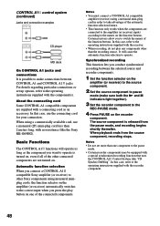
...recording between CONTROL A1 and CONTROL A1 jacks. Notes • Do not set up options, refer to the operating instructions supplied with the receiver. • When recording, do not play button on the recorder component. CONTROL A1 control system (continued) Jacks and...You must connect a CONTROL A1 compatible amplifier (receiver) using monaural miniplug cords, the function selector on the amplifier (or receiver) automatically switches to the correct input when you connect a CONTROL A1 compatible Sony amplifier (or receiver) to other Sony components using a monaural mini-plug cord in ...
...recording between CONTROL A1 and CONTROL A1 jacks. Notes • Do not set up options, refer to the operating instructions supplied with the receiver. • When recording, do not play button on the recorder component. CONTROL A1 control system (continued) Jacks and...You must connect a CONTROL A1 compatible amplifier (receiver) using monaural miniplug cords, the function selector on the amplifier (or receiver) automatically switches to the correct input when you connect a CONTROL A1 compatible Sony amplifier (or receiver) to other Sony components using a monaural mini-plug cord in ...
Operating Instructions (primary manual)
Page 51
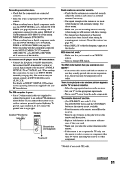
...FIXED (see the operating instructions supplied with your RF demodulator. For details on DOLBY DIGITAL RF hookups, see page 26) before operating the receiver or other than TV before recording with the component connected to the DIGITAL MD/DAT OUT terminals (STR-DB1070) or the DIGITAL ...MD/DAT or TAPE terminals (STR-DB1070) or the analog MD/TAPE terminals (STR-DB870). • When recording from the audio components. RDS does not work.* • Make sure that the antennas are connected securely. continued 51 Outdoor FM antenna Receiver ANTENNA AM U FM 75Ω COAXIAL Ground wire...
...FIXED (see the operating instructions supplied with your RF demodulator. For details on DOLBY DIGITAL RF hookups, see page 26) before operating the receiver or other than TV before recording with the component connected to the DIGITAL MD/DAT OUT terminals (STR-DB1070) or the DIGITAL ...MD/DAT or TAPE terminals (STR-DB1070) or the analog MD/TAPE terminals (STR-DB870). • When recording from the audio components. RDS does not work.* • Make sure that the antennas are connected securely. continued 51 Outdoor FM antenna Receiver ANTENNA AM U FM 75Ω COAXIAL Ground wire...


