Service Manual
Page 2
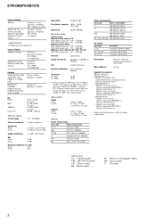
... 16.0 kg Supplied accessories FM wire antenna (1) AM loop antenna (1) • Models of area code U, CA Audio/video/control S connecting cord (1) Control S connecting cord (1) • STR-DB1070 only • Models of...(or 9 kHz), repeat the procedure. To reset the scale to 9 kHz or 10 kHz. After tuning in any AM station, turn off the receiver. Inputs (Digital) DVD/LD (Coaxial) DVD... ohms Usable sensitivity 11.2 dBf, 1 µV/75 ohms S/N Mono: Stereo: 76 dB 70 dB Harmonic distortion at 1 kHz Mono: 0.3% Stereo: 0.5% Separation 45 dB at 1 kHz Frequency response 30 Hz - 15...
... 16.0 kg Supplied accessories FM wire antenna (1) AM loop antenna (1) • Models of area code U, CA Audio/video/control S connecting cord (1) Control S connecting cord (1) • STR-DB1070 only • Models of...(or 9 kHz), repeat the procedure. To reset the scale to 9 kHz or 10 kHz. After tuning in any AM station, turn off the receiver. Inputs (Digital) DVD/LD (Coaxial) DVD... ohms Usable sensitivity 11.2 dBf, 1 µV/75 ohms S/N Mono: Stereo: 76 dB 70 dB Harmonic distortion at 1 kHz Mono: 0.3% Stereo: 0.5% Separation 45 dB at 1 kHz Frequency response 30 Hz - 15...
Service Manual
Page 12
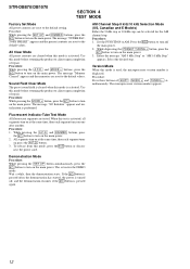
... pressing the [SET UP] button simultaneously, press the I /1 button to turn on the main power. 3. STR-DB870/DB1070 SECTION 4 TEST MODE Factory Set Mode All preset contents are reset to the default values. Use this mode before returning the product to turn on at the same time, then ...Field Clear Mode The preset sound field is cleared when this test is activated. Select the desired step. All Clear Mode All preset contents are reset to clients upon completion of repair. When this mode is performed. Procedure: While pressing the [MODE +] button, press the I /1 button...
... pressing the [SET UP] button simultaneously, press the I /1 button to turn on the main power. 3. STR-DB870/DB1070 SECTION 4 TEST MODE Factory Set Mode All preset contents are reset to the default values. Use this mode before returning the product to turn on at the same time, then ...Field Clear Mode The preset sound field is cleared when this test is activated. Select the desired step. All Clear Mode All preset contents are reset to clients upon completion of repair. When this mode is performed. Procedure: While pressing the [MODE +] button, press the I /1 button...
Service Manual
Page 15
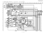
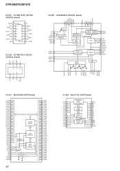
...FM 75Ω COAXIAL *FM/AM TUNER UNIT STEREO TUNED MUTING R CH GND L CH FM... DET OUT VDD 12V VDD 3.3V FMIF OUT GND DO CLOCK DATA CE *SUPPLIED AS THE ASSEMBLED BLOCK (Page 23) DVD/LD OPTICAL IN DIGITAL TV/SAT OPTICAL IN (DB870) MD/TAPE OPTICAL IN MD/DAT OPTICAL IN (DB1070... (US,CND) 15P (DB1070:AEP,UK,E,CH) 11P ...SYNC DB870:CND /DB1070 P/N GND_A1 CTRL A1...FB1401 21A DIGITAL OPTICAL RECEIVER IC1401 TORX179 R1406 100 ...OPTICAL RECEIVER IC1402 TORX178 DIGITAL OPTICAL RECEIVER IC1403... AUDIO INTERFACE RECEIVER IC1408 LC89056W-E...STR-DB870/DB1070 L1...
...FM 75Ω COAXIAL *FM/AM TUNER UNIT STEREO TUNED MUTING R CH GND L CH FM... DET OUT VDD 12V VDD 3.3V FMIF OUT GND DO CLOCK DATA CE *SUPPLIED AS THE ASSEMBLED BLOCK (Page 23) DVD/LD OPTICAL IN DIGITAL TV/SAT OPTICAL IN (DB870) MD/TAPE OPTICAL IN MD/DAT OPTICAL IN (DB1070... (US,CND) 15P (DB1070:AEP,UK,E,CH) 11P ...SYNC DB870:CND /DB1070 P/N GND_A1 CTRL A1...FB1401 21A DIGITAL OPTICAL RECEIVER IC1401 TORX179 R1406 100 ...OPTICAL RECEIVER IC1402 TORX178 DIGITAL OPTICAL RECEIVER IC1403... AUDIO INTERFACE RECEIVER IC1408 LC89056W-E...STR-DB870/DB1070 L1...
Service Manual
Page 42
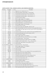
STR-DB870/DB1070 IC1407 TC7WH157FU (TE12R) (DIGITAL Board) SELECT 111 1A 2 INPUT 1B 3 OUTPUT 1Y 4 2A 5 INPUT 2B 6 OUTPUT 2Y 7 GND 8 S 1A G 1B 4A 1Y 4B 2A 4Y ... 24 HVO1 25 VDISP 26 VDD 27 DIN 28 DOUT 29 CLK 30 LS 31 CL 32 CHG 33 L-GND 34 D-GND 35 OUTPUT CIRCUIT RESET C 60BIT R REGISTER SI 60BIT C SHIFT SO R REGISTER 42 70 HVO26 69 HVO27 68 HVO28 67 HVO29 66 HVO30 65 HVO31 64 HVO32 63 HVO33 62...
STR-DB870/DB1070 IC1407 TC7WH157FU (TE12R) (DIGITAL Board) SELECT 111 1A 2 INPUT 1B 3 OUTPUT 1Y 4 2A 5 INPUT 2B 6 OUTPUT 2Y 7 GND 8 S 1A G 1B 4A 1Y 4B 2A 4Y ... 24 HVO1 25 VDISP 26 VDD 27 DIN 28 DOUT 29 CLK 30 LS 31 CL 32 CHG 33 L-GND 34 D-GND 35 OUTPUT CIRCUIT RESET C 60BIT R REGISTER SI 60BIT C SHIFT SO R REGISTER 42 70 HVO26 69 HVO27 68 HVO28 67 HVO29 66 HVO30 65 HVO31 64 HVO32 63 HVO33 62...

Service Manual
Page 43
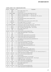
... Serial dara input from the system controller (IC1703) I Clock signal input from the system controller (IC1703) I Latch signal input from the system controllrt (IC1703) I Reset signal input from the system controller (IC1703) I Serial clock signal input from the audio DSP2 (IC1601) O Serial clock signal output terminal Not used (open) I Bit...terminal O Lerge external capacitor is used (open ) - Ground terminal (for analog) - Power supply terminal (+5V) - Power supply terminal (+5V) - Ground terminal (for analog) - STR-DB870/DB1070 5-25. Ground terminal (for analog) -
... Serial dara input from the system controller (IC1703) I Clock signal input from the system controller (IC1703) I Latch signal input from the system controllrt (IC1703) I Reset signal input from the system controller (IC1703) I Serial clock signal input from the audio DSP2 (IC1601) O Serial clock signal output terminal Not used (open) I Bit...terminal O Lerge external capacitor is used (open ) - Ground terminal (for analog) - Power supply terminal (+5V) - Power supply terminal (+5V) - Ground terminal (for analog) - STR-DB870/DB1070 5-25. Ground terminal (for analog) -
Service Manual
Page 44
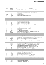
... I Mode setting input terminal (fixed at "L") 47 CKSEL1 I System clock select signal input from the system controller (IC1703) 48 XMODE I Reset signal input from the select switch (IC1406) O Amp integrate data input terminal Not used (fixed at "L") I Amp integrate data input terminal ...(for digital) 43 DVDD - Power supply terminal (+5V) (for PLL is connected to the system controller (IC1703) 18 DGND - STR-DB870/DB1070 • DIGITAL BOARD IC1408 LC89056W-E (DIGITAL AUDIO INTERFACE RECEIVER) Pin No. 1 2 3 4 5 6 7 8 9 10 11 12 13 14 Pin Name DISEL DOUT DIN0 DIN1 DIN2...
... I Mode setting input terminal (fixed at "L") 47 CKSEL1 I System clock select signal input from the system controller (IC1703) 48 XMODE I Reset signal input from the select switch (IC1406) O Amp integrate data input terminal Not used (fixed at "L") I Amp integrate data input terminal ...(for digital) 43 DVDD - Power supply terminal (+5V) (for PLL is connected to the system controller (IC1703) 18 DGND - STR-DB870/DB1070 • DIGITAL BOARD IC1408 LC89056W-E (DIGITAL AUDIO INTERFACE RECEIVER) Pin No. 1 2 3 4 5 6 7 8 9 10 11 12 13 14 Pin Name DISEL DOUT DIN0 DIN1 DIN2...

Service Manual
Page 45
... I/O Audio clock signal (384fs/256fs) in/out terminal O Audio serial data output to the audio DSP2 (IC1601) - Ground terminal I Reset signal input from the audio interface receiver (IC1408) - Ground terminal O Host acknowledge signal output to the system controller (IC1703) I Host serial data input from the system contrller ... BCKI2 SDI2 VSS HACN HDIN HCLK HDOUT HCS SDCLK CLKEN RAS VDDI VSS CAS DQM/OE0 CS0 WE0 VDDE WMD1 VSS I/O Description - Ground terminal 45 STR-DB870/DB1070 • DIGITAL BOARD IC1501 CDX9617R (AUDIO DSP1) Pin No. 1 2 3 4 5 6 7 8 9 10 11 12 13 14 15 16...
... I/O Audio clock signal (384fs/256fs) in/out terminal O Audio serial data output to the audio DSP2 (IC1601) - Ground terminal I Reset signal input from the audio interface receiver (IC1408) - Ground terminal O Host acknowledge signal output to the system controller (IC1703) I Host serial data input from the system contrller ... BCKI2 SDI2 VSS HACN HDIN HCLK HDOUT HCS SDCLK CLKEN RAS VDDI VSS CAS DQM/OE0 CS0 WE0 VDDE WMD1 VSS I/O Description - Ground terminal 45 STR-DB870/DB1070 • DIGITAL BOARD IC1501 CDX9617R (AUDIO DSP1) Pin No. 1 2 3 4 5 6 7 8 9 10 11 12 13 14 15 16...
Service Manual
Page 47
... mode setting terminal (fixed at "H") Mode select signal input terminal "L": 384fs, "H": 256fs Mode select signal input terminal "L": single chip mode, "H": can not use Ground terminal Reset signal input from the system controller (IC1703) Ground terminal Serial clock signal output to the D/A converter (IC1201, 1202) Power supply terminal (+2.5V) (for PLL) Sync... the S-RAM (IC1602) Power supply terminal (+3.3V) Ground terminal Two-way data bus with the S-RAM (IC1602) Address signal output to the S-RAM (IC1602) 47 STR-DB870/DB1070 • DIGITAL BOARD IC1601 CXD9616R (AUDIO DSP2) Pin No.
... mode setting terminal (fixed at "H") Mode select signal input terminal "L": 384fs, "H": 256fs Mode select signal input terminal "L": single chip mode, "H": can not use Ground terminal Reset signal input from the system controller (IC1703) Ground terminal Serial clock signal output to the D/A converter (IC1201, 1202) Power supply terminal (+2.5V) (for PLL) Sync... the S-RAM (IC1602) Power supply terminal (+3.3V) Ground terminal Two-way data bus with the S-RAM (IC1602) Address signal output to the S-RAM (IC1602) 47 STR-DB870/DB1070 • DIGITAL BOARD IC1601 CXD9616R (AUDIO DSP2) Pin No.
Service Manual
Page 51
... to the audio DSP1 (IC1501) 85 HCS1 O Host chip select signal output to the digital audio interface receiver (IC1408) 76 DO I Data input from the reset signal generator (IC1702) 56 VCC - Not used (fixed at "H" ) 55 RSTX I Not used ...at "L" ) 47 ERROR I Error signal input from the audio DSP (IC1601) 48 NC I System reset signal input from the digital audio interface receiver (IC1408) 77 VCC - Power supply terminal (+3.3V) 69 XSTATE I Clock status flag signal input from ... A1) 87 A1 OUT O Audio bus output terminal (control A1) 51 STR-DB870/DB1070 Pin No.
... to the audio DSP1 (IC1501) 85 HCS1 O Host chip select signal output to the digital audio interface receiver (IC1408) 76 DO I Data input from the reset signal generator (IC1702) 56 VCC - Not used (fixed at "H" ) 55 RSTX I Not used ...at "L" ) 47 ERROR I Error signal input from the audio DSP (IC1601) 48 NC I System reset signal input from the digital audio interface receiver (IC1408) 77 VCC - Power supply terminal (+3.3V) 69 XSTATE I Clock status flag signal input from ... A1) 87 A1 OUT O Audio bus output terminal (control A1) 51 STR-DB870/DB1070 Pin No.

Service Manual
Page 52
... audio DSP1 (IC1501) 90 PM1 O PLL initialize signal output to the audio DSP1 (IC1501) 91 ADC : RST O Reset signal output to the A/D converter (IC1101) 92 DACINT O Reset signal output to the D/A converter (IC1201) 93 DA1LAT O Serial data latch pulse output to the D/A converter (IC1201) ...) 52 Ground terminal (for analog) 129 AVRH - Connect to the EEPROM (IC1701) 101 VSS - Ground terminal (for analog) 131 AVSS - STR-DB870/DB1070 Pin No. Not used (open ) 125 NC - DIRECT O MULT/2CH DIRECT select signal output terminal Not used (open ) 124 NC - ...
... audio DSP1 (IC1501) 90 PM1 O PLL initialize signal output to the audio DSP1 (IC1501) 91 ADC : RST O Reset signal output to the A/D converter (IC1101) 92 DACINT O Reset signal output to the D/A converter (IC1201) 93 DA1LAT O Serial data latch pulse output to the D/A converter (IC1201) ...) 52 Ground terminal (for analog) 129 AVRH - Connect to the EEPROM (IC1701) 101 VSS - Ground terminal (for analog) 131 AVSS - STR-DB870/DB1070 Pin No. Not used (open ) 125 NC - DIRECT O MULT/2CH DIRECT select signal output terminal Not used (open ) 124 NC - ...

Operating Instructions (primary manual)
Page 18
...the IMPEDANCE SELECTOR to all of their factory settings. • The sound field memorized for 5 seconds. Check the operating instructions supplied with your receiver for the first time, or when you 're not sure of the following . However, even if one speaker within this range is output from...reset to -∞ dB. 18 The remaining jack can use the PRE OUT jacks. Make sure to another amplifier, connect that amplifier to "4Ω". Note Be sure to either of 8 ohms or higher, and set the IMPEDANCE SELECTOR to the PRE OUT FRONT L and R jacks. 2ND ROOM hookup (STR-DB1070...
...the IMPEDANCE SELECTOR to all of their factory settings. • The sound field memorized for 5 seconds. Check the operating instructions supplied with your receiver for the first time, or when you 're not sure of the following . However, even if one speaker within this range is output from...reset to -∞ dB. 18 The remaining jack can use the PRE OUT jacks. Make sure to another amplifier, connect that amplifier to "4Ω". Note Be sure to either of 8 ohms or higher, and set the IMPEDANCE SELECTOR to the PRE OUT FRONT L and R jacks. 2ND ROOM hookup (STR-DB1070...
Operating Instructions (primary manual)
Page 37
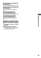
.../Frequency) Lets you adjust the gain and frequency of treble. Surround speaker treble adjustment (Gain/Frequency) Lets you adjust the gain and frequency of bass. Resetting customized sound fields to the factory settings 1 If the power is on, press ?/1 to turn off the power. 2 Hold down MODE + and press ?/1. Enjoying Surround... back speaker treble adjustment (Gain/Frequency) Lets you adjust the gain and frequency of bass. "S.F Initialize" appears in the display and all sound fields are reset at once. 37
.../Frequency) Lets you adjust the gain and frequency of treble. Surround speaker treble adjustment (Gain/Frequency) Lets you adjust the gain and frequency of bass. Resetting customized sound fields to the factory settings 1 If the power is on, press ?/1 to turn off the power. 2 Hold down MODE + and press ?/1. Enjoying Surround... back speaker treble adjustment (Gain/Frequency) Lets you adjust the gain and frequency of bass. "S.F Initialize" appears in the display and all sound fields are reset at once. 37

Operating Instructions (primary manual)
Page 53
... (37 steps) 1.0 kHz~10 kHz (23 steps) ±10 dB, 1 dB step FM tuner section Tuning range 87.5 - 108.0 MHz Antenna terminals 75 ohms, unbalanced Sensitivity Mono: Stereo: 18.3 dBf, 2.2 µV/75 ohms 38.3 dBf, 22.5 µV/75 ohms Usable sensitivity.../m, 400 kHz) Selectivity At 9 kHz: At 10 kHz: 35 dB 40 dB 6) You can change the tuning scale. continued 53 To reset the scale to 9 kHz or 10 kHz. Impedance: - Inputs (Digital) DVD/LD (Coaxial) DVD/LD, TV/SAT, MD/DAT, MD... INPUT SHORT. 5) Weighted network, input level. After tuning in any AM station, turn off the receiver.
... (37 steps) 1.0 kHz~10 kHz (23 steps) ±10 dB, 1 dB step FM tuner section Tuning range 87.5 - 108.0 MHz Antenna terminals 75 ohms, unbalanced Sensitivity Mono: Stereo: 18.3 dBf, 2.2 µV/75 ohms 38.3 dBf, 22.5 µV/75 ohms Usable sensitivity.../m, 400 kHz) Selectivity At 9 kHz: At 10 kHz: 35 dB 40 dB 6) You can change the tuning scale. continued 53 To reset the scale to 9 kHz or 10 kHz. Impedance: - Inputs (Digital) DVD/LD (Coaxial) DVD/LD, TV/SAT, MD/DAT, MD... INPUT SHORT. 5) Weighted network, input level. After tuning in any AM station, turn off the receiver.
Operating Instructions (primary manual)
Page 66
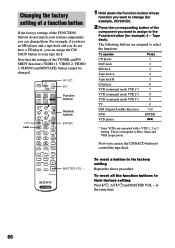
...the Function button whose function you want to control the tape deck. These correspond to its factory setting Repeat the above procedure. To reset all the function buttons to select the functions: To operate CD player Press 1 DAT deck 2 MD deck 3 Tape deck A ... deck B 5 LD player 6 VCR (command mode VTR 1*) 7 VCR (command mode VTR 2*) 8 VCR (command mode VTR 3*) 9 TV 0 DSS (Digital Satellite Receiver) >10 DVD VCD player ENTER . * Sony VCRs are operated with a VTR 1, 2 or 3 setting. SUB CH + 0 ) DISPLAY 9 P IN P ( JUMP WIDE P p SOUND FIELD A.F.D. 2CH/OFF...
...the Function button whose function you want to control the tape deck. These correspond to its factory setting Repeat the above procedure. To reset all the function buttons to select the functions: To operate CD player Press 1 DAT deck 2 MD deck 3 Tape deck A ... deck B 5 LD player 6 VCR (command mode VTR 1*) 7 VCR (command mode VTR 2*) 8 VCR (command mode VTR 3*) 9 TV 0 DSS (Digital Satellite Receiver) >10 DVD VCD player ENTER . * Sony VCRs are operated with a VTR 1, 2 or 3 setting. SUB CH + 0 ) DISPLAY 9 P IN P ( JUMP WIDE P p SOUND FIELD A.F.D. 2CH/OFF...


