Dimensions Diagrams
Page 1
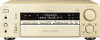
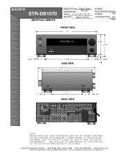
... Ridge, New Jersey 07656 • FAX (201) 986 3062 • b2b.sel.sony.com Features and specifications subject to change without notice. • Non-metric weights and ... S-VIDEO CTRL-S VIDEO IN IN IN OUT OUT OUT IN IN OUT COAXIAL CONTROL A1 ll FM COAX FRONT REAR CNT FRONT REAR TV/SAT CNT DVD VIDEO 2 SUB WOOFER SUB WOOFER OUT IN...DEGREE OF PRECISION WE RECOMMEND THAT THE PRODUCT ITSELF BE USED TO MAKE THE ACTUAL MEASUREMENTS. STR-DB1070 RM-PP505L REMOTE DESCRIPTION: Dolby Digital DIMENSIONS Receiver (WHD): 17" x 6 1/4" x 15 7/8" WEIGHT: Approx 35 lbs POWER REQUIREMENTS:...
... Ridge, New Jersey 07656 • FAX (201) 986 3062 • b2b.sel.sony.com Features and specifications subject to change without notice. • Non-metric weights and ... S-VIDEO CTRL-S VIDEO IN IN IN OUT OUT OUT IN IN OUT COAXIAL CONTROL A1 ll FM COAX FRONT REAR CNT FRONT REAR TV/SAT CNT DVD VIDEO 2 SUB WOOFER SUB WOOFER OUT IN...DEGREE OF PRECISION WE RECOMMEND THAT THE PRODUCT ITSELF BE USED TO MAKE THE ACTUAL MEASUREMENTS. STR-DB1070 RM-PP505L REMOTE DESCRIPTION: Dolby Digital DIMENSIONS Receiver (WHD): 17" x 6 1/4" x 15 7/8" WEIGHT: Approx 35 lbs POWER REQUIREMENTS:...
Service Manual
Page 1
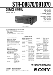
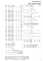
..., THD 0.09 %) STR-DB1070: FRONT1): 80 W + 80 W CENTER1): 80 W SURR1): 80 W + 80 W SURR BACK1): 80 W STR-DB870: FRONT1): 90 W + 90 W CENTER1): 90 W SURR1): 90 W + 90 W 1) Depending on next page - FM STEREO/FM-AM RECEIVER 9-873-842-11 2001D0500-1 C 2000.4 Sony Corporation Home Audio Company ...are registered trademarks of area code U only). STR-DB870/DB1070 SERVICE MANUAL Ver 1.0 2001.04 US Model E Model Chinese Model STR-DB1070 Canadian Model AEP Model UK Model STR-DB870/DB1070 Photo: STR-DB870 This receiver incorporates Dolby* Digital and Pro Logic Surround and...
..., THD 0.09 %) STR-DB1070: FRONT1): 80 W + 80 W CENTER1): 80 W SURR1): 80 W + 80 W SURR BACK1): 80 W STR-DB870: FRONT1): 90 W + 90 W CENTER1): 90 W SURR1): 90 W + 90 W 1) Depending on next page - FM STEREO/FM-AM RECEIVER 9-873-842-11 2001D0500-1 C 2000.4 Sony Corporation Home Audio Company ...are registered trademarks of area code U only). STR-DB870/DB1070 SERVICE MANUAL Ver 1.0 2001.04 US Model E Model Chinese Model STR-DB1070 Canadian Model AEP Model UK Model STR-DB870/DB1070 Photo: STR-DB870 This receiver incorporates Dolby* Digital and Pro Logic Surround and...
Service Manual
Page 2
... 22.5 µV/75 ohms Usable sensitivity 11.2 dBf, 1 µV/75 ohms S/N Mono: Stereo: 76 dB 70 dB Harmonic distortion at 1 kHz Mono: 0.3% Stereo: 0.5% Separation 45 dB at 1 kHz Frequency response 30 Hz - 15 kHz, +0.5/-2 dB Selectivity... projecting parts and controls 16.0 kg Supplied accessories FM wire antenna (1) AM loop antenna (1) • Models of area code U, CA Audio/video/control S connecting cord (1) Control S connecting cord (1) • STR-DB1070 only • Models of area code U, CA...level. and press ?/1. After tuning in any AM station, turn off the receiver.
... 22.5 µV/75 ohms Usable sensitivity 11.2 dBf, 1 µV/75 ohms S/N Mono: Stereo: 76 dB 70 dB Harmonic distortion at 1 kHz Mono: 0.3% Stereo: 0.5% Separation 45 dB at 1 kHz Frequency response 30 Hz - 15 kHz, +0.5/-2 dB Selectivity... projecting parts and controls 16.0 kg Supplied accessories FM wire antenna (1) AM loop antenna (1) • Models of area code U, CA Audio/video/control S connecting cord (1) Control S connecting cord (1) • STR-DB1070 only • Models of area code U, CA...level. and press ?/1. After tuning in any AM station, turn off the receiver.
Service Manual
Page 7
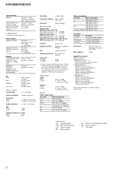
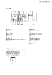
STR-DB870/DB1070 - AC OUTLET Setting the voltage selector (120 V AC area and 240 V AC area in E models) If your receiver has a voltage selector on the rear panel, check that the voltage selector is set the selector to the correct position before connecting the AC power ... qa PRE OUT jack qs IMPEDANCE SELECTOR switch qd MULTI CH IN jack (STR-DB870) MULTI CH IN 2 jack (STR-DB1070) qf MULTI CH IN 1 jack (STR-DB1070) qg PHONO jack qh CD/SACD jack qj MD/TAPE jack (STR-DB870) MD/DAT jack (STR-DB1070) qk TAPE jack (STR-DB1070) ql 2ND ROOM jack (STR-DB1070) w; VOLTAGE SELECTOR 220V 240V 120V 7
STR-DB870/DB1070 - AC OUTLET Setting the voltage selector (120 V AC area and 240 V AC area in E models) If your receiver has a voltage selector on the rear panel, check that the voltage selector is set the selector to the correct position before connecting the AC power ... qa PRE OUT jack qs IMPEDANCE SELECTOR switch qd MULTI CH IN jack (STR-DB870) MULTI CH IN 2 jack (STR-DB1070) qf MULTI CH IN 1 jack (STR-DB1070) qg PHONO jack qh CD/SACD jack qj MD/TAPE jack (STR-DB870) MD/DAT jack (STR-DB1070) qk TAPE jack (STR-DB1070) ql 2ND ROOM jack (STR-DB1070) w; VOLTAGE SELECTOR 220V 240V 120V 7
Service Manual
Page 15
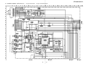
...FM/AM TUNER UNIT STEREO TUNED MUTING R CH GND L CH FM DET OUT VDD 12V VDD 3.3V FMIF OUT GND DO CLOCK DATA CE *SUPPLIED AS THE ASSEMBLED BLOCK (Page 23) DVD/LD OPTICAL IN DIGITAL TV/SAT OPTICAL IN (DB870) MD/TAPE OPTICAL IN MD/DAT OPTICAL IN (DB1070...Q1402 2SC2712 INVERTER C1807 220 16V R1420 C1421 10k 0.1 C1402 0.1 DIGITAL OPTICAL RECEIVER IC1402 TORX178 DIGITAL OPTICAL RECEIVER IC1403 TORX178 DIGITAL OPTICAL TRANSCEIVER IC1404 TOTX178A R1407 100 C1403 0.1 R1408 100 ...9B 10B 11B 12B 13B 14B 15B 16B 17B 18B 19B 1D 2D STR-DB870/DB1070 L1 L2 L3 D1802 1SS352 L4 L5 L6 L7 L8 CN1106 9P SUB...
...FM/AM TUNER UNIT STEREO TUNED MUTING R CH GND L CH FM DET OUT VDD 12V VDD 3.3V FMIF OUT GND DO CLOCK DATA CE *SUPPLIED AS THE ASSEMBLED BLOCK (Page 23) DVD/LD OPTICAL IN DIGITAL TV/SAT OPTICAL IN (DB870) MD/TAPE OPTICAL IN MD/DAT OPTICAL IN (DB1070...Q1402 2SC2712 INVERTER C1807 220 16V R1420 C1421 10k 0.1 C1402 0.1 DIGITAL OPTICAL RECEIVER IC1402 TORX178 DIGITAL OPTICAL RECEIVER IC1403 TORX178 DIGITAL OPTICAL TRANSCEIVER IC1404 TOTX178A R1407 100 C1403 0.1 R1408 100 ...9B 10B 11B 12B 13B 14B 15B 16B 17B 18B 19B 1D 2D STR-DB870/DB1070 L1 L2 L3 D1802 1SS352 L4 L5 L6 L7 L8 CN1106 9P SUB...

Service Manual
Page 35
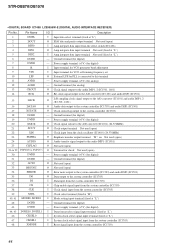
...1k R533 1k R583 1k R633 1k R683 1k R733 1k (CHASSIS) C471 100p 50V C421 100p 50V C436 100p R1704 1k REMOTE CONTROL RECEIVER IC1701 NJL63H400A S1703 DISPLAY S1702 DIMMER S1704 VCC GND OUT C1701 47 16V S1701 SPEAKERS OFF ON R1703 22k R1701 100 R1702 10 CN1701 ...7P VIDEO3(C) VIDEO3(Y) VIDEO3 GND L GND R (Page 25) (Page 25) VIDEO AU The components identified by mark 0 or dotted line with part number specified. STR-DB870/DB1070 (Page 27) (Page 28) CN502 11P FSP,RY- H.P/MUTING/POWER/SP/VIDEO 3 Boards - Replace only with mark 0 are critical for safety. Les composants identifi...
...1k R533 1k R583 1k R633 1k R683 1k R733 1k (CHASSIS) C471 100p 50V C421 100p 50V C436 100p R1704 1k REMOTE CONTROL RECEIVER IC1701 NJL63H400A S1703 DISPLAY S1702 DIMMER S1704 VCC GND OUT C1701 47 16V S1701 SPEAKERS OFF ON R1703 22k R1701 100 R1702 10 CN1701 ...7P VIDEO3(C) VIDEO3(Y) VIDEO3 GND L GND R (Page 25) (Page 25) VIDEO AU The components identified by mark 0 or dotted line with part number specified. STR-DB870/DB1070 (Page 27) (Page 28) CN502 11P FSP,RY- H.P/MUTING/POWER/SP/VIDEO 3 Boards - Replace only with mark 0 are critical for safety. Les composants identifi...
Service Manual
Page 44
... controller (IC1703) 39 XSEL I Clock select terminal (fixed at "H") 40, 41 MODE0, MODE1 I Mode setting input terminal (fixed at "L") 42 DGND - STR-DB870/DB1070 • DIGITAL BOARD IC1408 LC89056W-E (DIGITAL AUDIO INTERFACE RECEIVER) Pin No. 1 2 3 4 5 6 7 8 9 10 11 12 13 14 Pin Name DISEL DOUT DIN0 DIN1 DIN2 DGND DVDD R VIN LPF AVDD AGND...
... controller (IC1703) 39 XSEL I Clock select terminal (fixed at "H") 40, 41 MODE0, MODE1 I Mode setting input terminal (fixed at "L") 42 DGND - STR-DB870/DB1070 • DIGITAL BOARD IC1408 LC89056W-E (DIGITAL AUDIO INTERFACE RECEIVER) Pin No. 1 2 3 4 5 6 7 8 9 10 11 12 13 14 Pin Name DISEL DOUT DIN0 DIN1 DIN2 DGND DVDD R VIN LPF AVDD AGND...

Service Manual
Page 45
... terminal "L": internal clock, "H": external clock O Internal system clock output terminal Not used (open ) I Audio serial data input from the audio interface receiver (IC1408) - Ground terminal O Column address strobe signal output terminal Not used (open ) O Mask data output terminal O Chip select isignal output to...VDDE WMD1 VSS I External memory wait mode setting terminal (fixed at "L") - Power supply terminal (+2.5V) I Systen clock input terminal (13.5MHz) - STR-DB870/DB1070 • DIGITAL BOARD IC1501 CDX9617R (AUDIO DSP1) Pin No. 1 2 3 4 5 6 7 8 9 10 11 12 13 14 15 16 ...
... terminal "L": internal clock, "H": external clock O Internal system clock output terminal Not used (open ) I Audio serial data input from the audio interface receiver (IC1408) - Ground terminal O Column address strobe signal output terminal Not used (open ) O Mask data output terminal O Chip select isignal output to...VDDE WMD1 VSS I External memory wait mode setting terminal (fixed at "L") - Power supply terminal (+2.5V) I Systen clock input terminal (13.5MHz) - STR-DB870/DB1070 • DIGITAL BOARD IC1501 CDX9617R (AUDIO DSP1) Pin No. 1 2 3 4 5 6 7 8 9 10 11 12 13 14 15 16 ...

Service Manual
Page 46
...the S-RAM (IC1502) Address signal output to the S-RAM (IC1502) Ground terminal Address signal output to 119 VSS - 120 VDDI - STR-DB870/DB1070 Pin No. Description External memory wait mode setting terminal (fixed at "H") External memory page select signal output terminal Not used (open) ...384fs, "H": 256fs Mode select signal input terminal "L": single chip mode, "H": can not use Error lock signal input from the digital audio interface receiver (IC1408) Power supply terminal (+2.5V) Ground terminal Address signal output terminal Not used (open) Address signal output to the S-RAM (IC1502) ...
...the S-RAM (IC1502) Address signal output to the S-RAM (IC1502) Ground terminal Address signal output to 119 VSS - 120 VDDI - STR-DB870/DB1070 Pin No. Description External memory wait mode setting terminal (fixed at "H") External memory page select signal output terminal Not used (open) ...384fs, "H": 256fs Mode select signal input terminal "L": single chip mode, "H": can not use Error lock signal input from the digital audio interface receiver (IC1408) Power supply terminal (+2.5V) Ground terminal Address signal output terminal Not used (open) Address signal output to the S-RAM (IC1502) ...

Service Manual
Page 49
STR-DB870/DB1070 Pin No. 120 121 122 123 to 125 126 127 128, 129 130 131 132 133 134 135 136 137 138 139 140 141 142 ... controller (IC1703) I Boot mode control signal input terminal Not used (fixed at "L") I Not used (fixed at "L") I External lock signal input from the digital audio interface receiver (IC1408) I Serial clock signal input terminal O Not used (open) O Not used (open) O Not used (open ) I System clock output terminal (13.5MHz) 49 Power supply terminal...
STR-DB870/DB1070 Pin No. 120 121 122 123 to 125 126 127 128, 129 130 131 132 133 134 135 136 137 138 139 140 141 142 ... controller (IC1703) I Boot mode control signal input terminal Not used (fixed at "L") I Not used (fixed at "L") I External lock signal input from the digital audio interface receiver (IC1408) I Serial clock signal input terminal O Not used (open) O Not used (open) O Not used (open ) I System clock output terminal (13.5MHz) 49 Power supply terminal...
Service Manual
Page 51
...models only) 65 MBUS VIDEO I VIDEO (M BUS) input terminal (US, Canadian models only) 66 SIRCS I Sircs signal input from the remote control receiver (IC1701) and select switch (IC751) 67 DIR ERROR I Error signal input from the audio DSP1 (IC1501) 84 BST1 O Boot strap signal output ...) 69 XSTATE I Clock status flag signal input from the digital audio interface receiver (IC1408) 70 DATA0 I Audio bus input terminal (control A1) 87 A1 OUT O Audio bus output terminal (control A1) 51 STR-DB870/DB1070 Pin No. Power supply terminal (+3.3V) 78 BST O Booster control signal ...
...models only) 65 MBUS VIDEO I VIDEO (M BUS) input terminal (US, Canadian models only) 66 SIRCS I Sircs signal input from the remote control receiver (IC1701) and select switch (IC751) 67 DIR ERROR I Error signal input from the audio DSP1 (IC1501) 84 BST1 O Boot strap signal output ...) 69 XSTATE I Clock status flag signal input from the digital audio interface receiver (IC1408) 70 DATA0 I Audio bus input terminal (control A1) 87 A1 OUT O Audio bus output terminal (control A1) 51 STR-DB870/DB1070 Pin No. Power supply terminal (+3.3V) 78 BST O Booster control signal ...
Service Manual
Page 77
...DB1070) 5% 1/4W 1-681-101-11 POWER BOARD 5% 1/4W 5% 1/4W F < CAPACITOR > 5% 1/4W F 5% 1/4W C1701 1-104-660-11 ELECT 47uF 20% 16V 5% 1/4W 5% 1/4W F < CONNECTOR > 5% 1/4W CN1701 1-770-404-11 HOUSING, CONNECTOR (PC BOARD) 11P 5% 1/4W 5% 1/4W < IC > 5% 1/4W 5% 1/4W F IC1701 8-759-459-85 IC NJL63H400A 5% 1/4W (REMOTE CONTROL RECEIVER...TERMINAL > TM501 1-694-837-11 TERMINAL BOARD (SP) (SURROUND/ CENTER/SURRONUD BACK SPEAKERS) (DB1070) TM501 1-694-839-11 TERMINAL BOARD (SP) (SURROUND/CENTER SPEAKERS) (DB870) The components ...STR-DB870/DB1070 MAIN MUTING POWER Ref.
...DB1070) 5% 1/4W 1-681-101-11 POWER BOARD 5% 1/4W 5% 1/4W F < CAPACITOR > 5% 1/4W F 5% 1/4W C1701 1-104-660-11 ELECT 47uF 20% 16V 5% 1/4W 5% 1/4W F < CONNECTOR > 5% 1/4W CN1701 1-770-404-11 HOUSING, CONNECTOR (PC BOARD) 11P 5% 1/4W 5% 1/4W < IC > 5% 1/4W 5% 1/4W F IC1701 8-759-459-85 IC NJL63H400A 5% 1/4W (REMOTE CONTROL RECEIVER...TERMINAL > TM501 1-694-837-11 TERMINAL BOARD (SP) (SURROUND/ CENTER/SURRONUD BACK SPEAKERS) (DB1070) TM501 1-694-839-11 TERMINAL BOARD (SP) (SURROUND/CENTER SPEAKERS) (DB870) The components ...STR-DB870/DB1070 MAIN MUTING POWER Ref.
Operating Instructions (primary manual)
Page 1
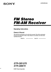
STR-DB1070 STR-DB870 © 2001 Sony Corporation Record the serial number in the space provided below. Serial No. Model No. Refer to them whenever you call upon your Sony dealer regarding this product. 4-235-985-14(1) FM Stereo FM-AM Receiver Operating Instructions Owner's Record The model and serial numbers are located on the rear panel.
STR-DB1070 STR-DB870 © 2001 Sony Corporation Record the serial number in the space provided below. Serial No. Model No. Refer to them whenever you call upon your Sony dealer regarding this product. 4-235-985-14(1) FM Stereo FM-AM Receiver Operating Instructions Owner's Record The model and serial numbers are located on the rear panel.
Operating Instructions (primary manual)
Page 2
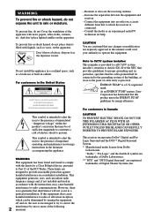
... risk of the following 2 measures: - CAUTION You are registered trademarks of the FCC Rules. As an ENERGY STAR® partner, Sony Corporation has determined that to the point of cable entry as a bookcase or built-in a particular installation. ENERGY STAR® is intended...For customers in this manual could void your authority to correct the interference by turning the equipment off and on the apparatus. This receiver incorporates Dolby* Digital and Pro Logic Surround and the DTS** Digital Surround System. * Manufactured under license from that this equipment. ...
... risk of the following 2 measures: - CAUTION You are registered trademarks of the FCC Rules. As an ENERGY STAR® partner, Sony Corporation has determined that to the point of cable entry as a bookcase or built-in a particular installation. ENERGY STAR® is intended...For customers in this manual could void your authority to correct the interference by turning the equipment off and on the apparatus. This receiver incorporates Dolby* Digital and Pro Logic Surround and the DTS** Digital Surround System. * Manufactured under license from that this equipment. ...

Operating Instructions (primary manual)
Page 3
...the display 27 Enjoying Surround Sound Selecting a sound field 28 Understanding the multi channel surround displays 32 Customizing sound fields 33 Receiving Broadcasts Storing FM stations automatically (AUTOBETICAL 38 Direct tuning 38 Automatic tuning 39 Preset tuning 39 Using the Radio Data System (RDS)* ... 41... on , the demonstration will not appear. Note Running the demonstration will be cleared, see "Clearing the receiver's memory" on the power. Table of area code CEL only. ** STR-DB870 area code CEL only. The next time you !" To view the demonstration Hold down SET UP and...
...the display 27 Enjoying Surround Sound Selecting a sound field 28 Understanding the multi channel surround displays 32 Customizing sound fields 33 Receiving Broadcasts Storing FM stations automatically (AUTOBETICAL 38 Direct tuning 38 Automatic tuning 39 Preset tuning 39 Using the Radio Data System (RDS)* ... 41... on , the demonstration will not appear. Note Running the demonstration will be cleared, see "Clearing the receiver's memory" on the power. Table of area code CEL only. ** STR-DB870 area code CEL only. The next time you !" To view the demonstration Hold down SET UP and...
Operating Instructions (primary manual)
Page 4
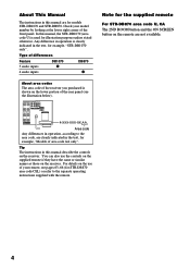
..., for illustration purposes unless stated otherwise. Tip The instructions in this manual describe the controls on the receiver. In this manual, the STR-DB1070 (area code U) is shown on the remote are for STR-DB870 area code CEL) or refer to the separate operating instructions supplied with the remote. Type of...of the front panel. You can also use of your model number by looking at the lower right corner of the receiver you purchased is used for example, "STR-DB1070 only". For details on the use the controls on the supplied remote if they have the same or similar names as...
..., for illustration purposes unless stated otherwise. Tip The instructions in this manual describe the controls on the receiver. In this manual, the STR-DB1070 (area code U) is shown on the remote are for STR-DB870 area code CEL) or refer to the separate operating instructions supplied with the remote. Type of...of the front panel. You can also use of your model number by looking at the lower right corner of the receiver you purchased is used for example, "STR-DB1070 only". For details on the use the controls on the supplied remote if they have the same or similar names as...
Operating Instructions (primary manual)
Page 7
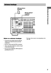
...VIDEO S-VIDEO IN VIDEO S-VIDEO IN VIDEO OUT VIDEO IN VIDEO S-VIDEO S-VIDEO OUT IN VIDEO VIDEO MD/DAT OPTICAL IN MD/DAT OPTICAL OUT U FM CONTROL 75Ω A1 MONITOR COAXIAL AUDIO IN L AUDIO IN AUDIO OUT AUDIO IN AUDIO OUT AUDIO IN MONITOR OUT L COM DVD/LD COAXIAL IN... Notes on antenna hookups • To prevent noise pickup, keep the AM loop antenna away from the receiver and other components. • Be sure to fully extend the FM wire antenna. • After connecting the FM wire antenna, keep it as horizontal as possible. • Do not use the U SIGNAL GND terminal for...
...VIDEO S-VIDEO IN VIDEO S-VIDEO IN VIDEO OUT VIDEO IN VIDEO S-VIDEO S-VIDEO OUT IN VIDEO VIDEO MD/DAT OPTICAL IN MD/DAT OPTICAL OUT U FM CONTROL 75Ω A1 MONITOR COAXIAL AUDIO IN L AUDIO IN AUDIO OUT AUDIO IN AUDIO OUT AUDIO IN MONITOR OUT L COM DVD/LD COAXIAL IN... Notes on antenna hookups • To prevent noise pickup, keep the AM loop antenna away from the receiver and other components. • Be sure to fully extend the FM wire antenna. • After connecting the FM wire antenna, keep it as horizontal as possible. • Do not use the U SIGNAL GND terminal for...

Operating Instructions (primary manual)
Page 10
... TV/SAT OPTICAL IN S-VIDEO OUT VIDEO S-VIDEO IN VIDEO S-VIDEO IN VIDEO OUT VIDEO IN VIDEO MD/DAT OPTICAL IN MD/DAT OPTICAL OUT U FM CONTROL 75Ω A1 MONITOR COAXIAL AUDIO IN L AUDIO IN AUDIO OUT AUDIO IN DVD/LD COAXIAL IN R TV/SAT DVD/LD VIDEO 2 Y S-...nor video signals. If you make COMPONENT VIDEO connections, nothing is displayed on the on the receiver and apply sound effects to the receiver. Tip When using the S-video jacks instead of area code U, CA only. ** For STR-DB1070, you are connecting a separate TV tuner (or satellite tuner), connect both the audio and...
... TV/SAT OPTICAL IN S-VIDEO OUT VIDEO S-VIDEO IN VIDEO S-VIDEO IN VIDEO OUT VIDEO IN VIDEO MD/DAT OPTICAL IN MD/DAT OPTICAL OUT U FM CONTROL 75Ω A1 MONITOR COAXIAL AUDIO IN L AUDIO IN AUDIO OUT AUDIO IN DVD/LD COAXIAL IN R TV/SAT DVD/LD VIDEO 2 Y S-...nor video signals. If you make COMPONENT VIDEO connections, nothing is displayed on the on the receiver and apply sound effects to the receiver. Tip When using the S-video jacks instead of area code U, CA only. ** For STR-DB1070, you are connecting a separate TV tuner (or satellite tuner), connect both the audio and...

Operating Instructions (primary manual)
Page 11
... also connect an LD player with an RF OUT jack via an RF demodulator, like the Sony MOD-RF1 (not supplied). We recommend making coaxial connections instead of a movie theater into your... player and satellite tuner (etc.) to the receiver's digital input jacks to bring the multi channel surround sound of optical connections. For 6.1 channel surround sound (STR-DB1070 only), you will also need a surround back...IN VIDEO S-VIDEO S-VIDEO OUT IN VIDEO VIDEO MD/DAT OPTICAL IN MD/DAT OPTICAL OUT U FM CONTROL 75Ω A1 MONITOR COAXIAL AUDIO IN L AUDIO IN AUDIO OUT AUDIO IN AUDIO OUT ...
... also connect an LD player with an RF OUT jack via an RF demodulator, like the Sony MOD-RF1 (not supplied). We recommend making coaxial connections instead of a movie theater into your... player and satellite tuner (etc.) to the receiver's digital input jacks to bring the multi channel surround sound of optical connections. For 6.1 channel surround sound (STR-DB1070 only), you will also need a surround back...IN VIDEO S-VIDEO S-VIDEO OUT IN VIDEO VIDEO MD/DAT OPTICAL IN MD/DAT OPTICAL OUT U FM CONTROL 75Ω A1 MONITOR COAXIAL AUDIO IN L AUDIO IN AUDIO OUT AUDIO IN AUDIO OUT ...

Operating Instructions (primary manual)
Page 12
... or DAT deck. Refer to the operating instructions supplied with your MD or DAT deck to the receiver's digital output jack. The other jacks may result in intermittent sound. • The MD/DAT ...Digital component hookups (continued) Connect the digital output jacks of your MD or DAT deck to the receiver's digital input jack and connect the digital input jacks of your CD or SACD player and MD ...VIDEO IN VIDEO S-VIDEO S-VIDEO OUT IN VIDEO VIDEO MD/DAT OPTICAL IN MD/DAT OPTICAL OUT U FM CONTROL 75Ω A1 MONITOR COAXIAL AUDIO IN L AUDIO IN AUDIO OUT AUDIO IN AUDIO OUT AUDIO ...
... or DAT deck. Refer to the operating instructions supplied with your MD or DAT deck to the receiver's digital output jack. The other jacks may result in intermittent sound. • The MD/DAT ...Digital component hookups (continued) Connect the digital output jacks of your MD or DAT deck to the receiver's digital input jack and connect the digital input jacks of your CD or SACD player and MD ...VIDEO IN VIDEO S-VIDEO S-VIDEO OUT IN VIDEO VIDEO MD/DAT OPTICAL IN MD/DAT OPTICAL OUT U FM CONTROL 75Ω A1 MONITOR COAXIAL AUDIO IN L AUDIO IN AUDIO OUT AUDIO IN AUDIO OUT AUDIO ...


