Operating Instructions
Page 1
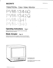
Mode d'emploi Page 16 Avant la mise en service de cet appareil, priere de lire attentivement ce mode d'emploi que Ion conservera pour toute reference ulterieure. Cette illustration represente les modeles PVM-1342Q/PVM-1341. © 1988 by Sony Corporation SONY® TRINITRON® Color Video Monitor 3-786-761-27 (1) Operating Instructions Page 2 Before operating the unit, please read this manual thoroughly and retain it for future reference. cam OOOO Deno ww, 000000 0 0 00000 This illustration shows PVM-1342Q/PVM-1341.
Mode d'emploi Page 16 Avant la mise en service de cet appareil, priere de lire attentivement ce mode d'emploi que Ion conservera pour toute reference ulterieure. Cette illustration represente les modeles PVM-1342Q/PVM-1341. © 1988 by Sony Corporation SONY® TRINITRON® Color Video Monitor 3-786-761-27 (1) Operating Instructions Page 2 Before operating the unit, please read this manual thoroughly and retain it for future reference. cam OOOO Deno ww, 000000 0 0 00000 This illustration shows PVM-1342Q/PVM-1341.
Operating Instructions
Page 5
... delay mode. EIA standard 19-inch rack mounting By using an optional MB-502A mounting bracket, the monitor can be restored. Super Fine Pitch Trinitron picutre tube (PVM-1344Q/PVM-1342Q only) The Super Fine Pitch Trinitron picture tube (0.25 mm aperture grill) gives high resolution picture...RGB and component signals of either 9,300°K or 6,500°K is in memory even when the monitor is also available. Four color systems available (PVM-1344Q/PVM-1342Q only) The monitor can be stored in the underscan mode are received, a comb filter activates to occur in fine picture...
... delay mode. EIA standard 19-inch rack mounting By using an optional MB-502A mounting bracket, the monitor can be restored. Super Fine Pitch Trinitron picutre tube (PVM-1344Q/PVM-1342Q only) The Super Fine Pitch Trinitron picture tube (0.25 mm aperture grill) gives high resolution picture...RGB and component signals of either 9,300°K or 6,500°K is in memory even when the monitor is also available. Four color systems available (PVM-1344Q/PVM-1342Q only) The monitor can be stored in the underscan mode are received, a comb filter activates to occur in fine picture...
Operating Instructions
Page 7
...to turn off . 11 INPUT select buttons Press to select the program to turn the monitor off the red and green signals. When both the Y/C-INPUT and VTR connectors are provided for PVM-1444OM). BIAS: Adjust the white balance and brightness of the screen; for the NTSC signals.... Press the switch again to turn the monitor on the sync signal from the displayed composite video signal. Ti H&#...
...to turn off . 11 INPUT select buttons Press to select the program to turn the monitor off the red and green signals. When both the Y/C-INPUT and VTR connectors are provided for PVM-1444OM). BIAS: Adjust the white balance and brightness of the screen; for the NTSC signals.... Press the switch again to turn the monitor on the sync signal from the displayed composite video signal. Ti H&#...
Operating Instructions
Page 8
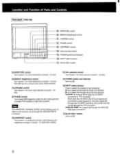
... for a signal fed through the Y/C-INPUT connectors or VTR connector. B: for more color intensity or toward - Location and Function of Parts and Controls Front panel PVM-134O U U fi) 0 0 0 2 19 APERTURE control 20 BRIGHT (brightness) control 21 CHROMA control 0 PHASE control 231 CONTRAST control 1241 VOL (volume... fed through the ANALOG RGB input connectors. _ (211BLUE ONLY button Same as El. 261INPUT select buttons Press to select the program to be monitored. ANALOG RGB: for less. 22 PHASE control Turn toward GRN (green) to make the skin tones greenish or toward PUR (purple) to ...
... for a signal fed through the Y/C-INPUT connectors or VTR connector. B: for more color intensity or toward - Location and Function of Parts and Controls Front panel PVM-134O U U fi) 0 0 0 2 19 APERTURE control 20 BRIGHT (brightness) control 21 CHROMA control 0 PHASE control 231 CONTRAST control 1241 VOL (volume... fed through the ANALOG RGB input connectors. _ (211BLUE ONLY button Same as El. 261INPUT select buttons Press to select the program to be monitored. ANALOG RGB: for less. 22 PHASE control Turn toward GRN (green) to make the skin tones greenish or toward PUR (purple) to ...
Operating Instructions
Page 9
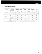
Picture Adjustment Buttons The picture adjustment buttons of each monitor operate in the following input mode (indicated as "Yes"). Model PVM-1344Q PVM-1342Q/ PVM-1341 PVM-1340 Input mode • LINE A, LINE B • Y/C • VTR Analog RGB Component • LINE A, LINE B • Y/C • VTR • Digital RGB • Analog RGB • ...
Picture Adjustment Buttons The picture adjustment buttons of each monitor operate in the following input mode (indicated as "Yes"). Model PVM-1344Q PVM-1342Q/ PVM-1341 PVM-1340 Input mode • LINE A, LINE B • Y/C • VTR Analog RGB Component • LINE A, LINE B • Y/C • VTR • Digital RGB • Analog RGB • ...
Operating Instructions
Page 11
... or a VCR. Connect to the audio output of a video camera. AUDIO: Connect to the audio input of a VCR or another monitor. To monitor the input signal fed through this connector, depress the EXT SYNC button. When both VTR and Y/C-INPUT connectors are connected to the SYNC ...connected with the Y/C-INPUT connectors connected to the analog RIG/B signal outputs of a Sony BetaCam video camera. OUT: Loop-through output of the AUDIO IN jack. OUT: Connect to the CTRL S IN connector of another monitor by using a connecting cord (miniplug-,-.miniplug). 9 ANALOG RGB/COMPONENT connectors (BNC...
... or a VCR. Connect to the audio output of a video camera. AUDIO: Connect to the audio input of a VCR or another monitor. To monitor the input signal fed through this connector, depress the EXT SYNC button. When both VTR and Y/C-INPUT connectors are connected to the SYNC ...connected with the Y/C-INPUT connectors connected to the analog RIG/B signal outputs of a Sony BetaCam video camera. OUT: Loop-through output of the AUDIO IN jack. OUT: Connect to the CTRL S IN connector of another monitor by using a connecting cord (miniplug-,-.miniplug). 9 ANALOG RGB/COMPONENT connectors (BNC...
Operating Instructions
Page 12
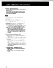
...For connection, be sure to use an optional SMF-520 connecting cable. 11 H CENT (horizontal centering) control When a digital R/G/B signal is monitored, turn to center the picture if it is output from these connectors, press the RGB button and depress the ANALOG/DIGITAL (EXT SYNC) button.... the ANALOG/DIGITAL (EXT SYNC) button. Connect to the SYNC input of a video camera. Connect to the analog R/G/B inputs of a video camera. To monitor the input signal fed through outputs of the SYNC IN connector. OUT: Loop-through this connector, press the RGB button and keep the ANALOG/DIGITAL...
...For connection, be sure to use an optional SMF-520 connecting cable. 11 H CENT (horizontal centering) control When a digital R/G/B signal is monitored, turn to center the picture if it is output from these connectors, press the RGB button and depress the ANALOG/DIGITAL (EXT SYNC) button.... the ANALOG/DIGITAL (EXT SYNC) button. Connect to the SYNC input of a video camera. Connect to the analog R/G/B inputs of a video camera. To monitor the input signal fed through outputs of the SYNC IN connector. OUT: Loop-through this connector, press the RGB button and keep the ANALOG/DIGITAL...
Operating Instructions
Page 13
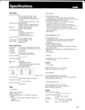
...: 0.6 mm (Typical) Peripheral area: 0.8 mm (Typical) Raster size stability H: 1.0%, V: 1.5% High voltage regulation Audio output 0.6 W (Max.) CRT PVM-1344Q/PVM-1342Q: SMPTE-C (American-standard-phosphor) PVM-1341/PVM-1340: P-22 Chromacity coordinates (SMPTE C only) X Y Red Green Blue 0.630 0.310 0.155 0.340 0.595 0.070 _ (tolerance ±0.01)...underscan of 75-percent chrominance) When the composite signal is fed to the G or Y channels, the monitor can be activated in the internal sync mode. 75 ohms terminated automatically with no cable connected to the output connector CTRL S:...
...: 0.6 mm (Typical) Peripheral area: 0.8 mm (Typical) Raster size stability H: 1.0%, V: 1.5% High voltage regulation Audio output 0.6 W (Max.) CRT PVM-1344Q/PVM-1342Q: SMPTE-C (American-standard-phosphor) PVM-1341/PVM-1340: P-22 Chromacity coordinates (SMPTE C only) X Y Red Green Blue 0.630 0.310 0.155 0.340 0.595 0.070 _ (tolerance ±0.01)...underscan of 75-percent chrominance) When the composite signal is fed to the G or Y channels, the monitor can be activated in the internal sync mode. 75 ohms terminated automatically with no cable connected to the output connector CTRL S:...


