Warranty Card
Page 2
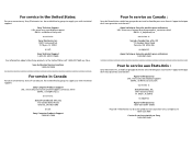
.... has established a group to supply you with technical support: Sony Technical Support URL: www.sony.com/displays/support EMAIL: [email protected] or write to : Sony of Canada Ltd. For service in the United States: For your convenience, Sony of Canada Ltd. has established a group to supply you with technical support: Sony Computer Products Support URL: www.sony.ca/sonyca/customersupport_contactus.shtml EMAIL...
.... has established a group to supply you with technical support: Sony Technical Support URL: www.sony.com/displays/support EMAIL: [email protected] or write to : Sony of Canada Ltd. For service in the United States: For your convenience, Sony of Canada Ltd. has established a group to supply you with technical support: Sony Computer Products Support URL: www.sony.ca/sonyca/customersupport_contactus.shtml EMAIL...
Operating Instructions
Page 1
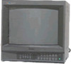
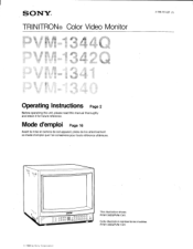
Mode d'emploi Page 16 Avant la mise en service de cet appareil, priere de lire attentivement ce mode d'emploi que Ion conservera pour toute reference ulterieure. Cette illustration represente les modeles PVM-1342Q/PVM-1341. © 1988 by Sony Corporation SONY® TRINITRON® Color Video Monitor 3-786-761-27 (1) Operating Instructions Page 2 Before operating the unit, please read this manual thoroughly and retain it for future reference. cam OOOO Deno ww, 000000 0 0 00000 This illustration shows PVM-1342Q/PVM-1341.
Mode d'emploi Page 16 Avant la mise en service de cet appareil, priere de lire attentivement ce mode d'emploi que Ion conservera pour toute reference ulterieure. Cette illustration represente les modeles PVM-1342Q/PVM-1341. © 1988 by Sony Corporation SONY® TRINITRON® Color Video Monitor 3-786-761-27 (1) Operating Instructions Page 2 Before operating the unit, please read this manual thoroughly and retain it for future reference. cam OOOO Deno ww, 000000 0 0 00000 This illustration shows PVM-1342Q/PVM-1341.
Operating Instructions
Page 2
... (servicing) instructions in Part 15 of the complete system has a label with the instructions manual, may cause interference to radio communications. This symbol is intended to alert the user to the presence of uninsulated "dangerous voltage" within the product's enclosure that the complete system (including this product. Refer to these numbers whenever you call upon your Sony dealer...
... (servicing) instructions in Part 15 of the complete system has a label with the instructions manual, may cause interference to radio communications. This symbol is intended to alert the user to the presence of uninsulated "dangerous voltage" within the product's enclosure that the complete system (including this product. Refer to these numbers whenever you call upon your Sony dealer...
Operating Instructions
Page 3
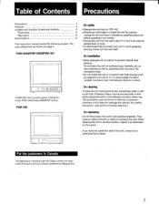
... make an ideal container in Canada This apparatus complies with a mild detergent solution. Table of Contents Precautions Precautions 3 Features 4 Location and function of parts and controls 6 Front panel 6 Rear panel 10 Specifications 13 This instruction manual covers the following models. PVM-13440/PVM-13420/PVM-1341 L___ rr. 2E,LAoMaoPou]; • PVM-1341 has no color system indicators. • Only PVM-1344O has a MEMORY button. On cleaning To keep...
... make an ideal container in Canada This apparatus complies with a mild detergent solution. Table of Contents Precautions Precautions 3 Features 4 Location and function of parts and controls 6 Front panel 6 Rear panel 10 Specifications 13 This instruction manual covers the following models. PVM-13440/PVM-13420/PVM-1341 L___ rr. 2E,LAoMaoPou]; • PVM-1341 has no color system indicators. • Only PVM-1344O has a MEMORY button. On cleaning To keep...
Operating Instructions
Page 4
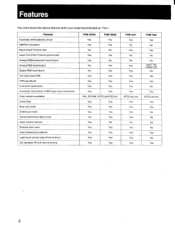
External sync input Color temperature selector Light-touch picture adjustment buttons EIA standard 19-inch rack mounting PVM-1344O PVM-1342Q ^ Yes Yes Yes Yes No ...PVM-1341 Yes No - Features Automatic white balance circuit SMPTE-C phosphor Black-tinted Trinitron tube Super Fine Pitch Trinitron picture tube Analog RGB/component input/output Analog RGB input/output Digital RGB input (9-pin) Y/C input (4-pin DIN) VTR input (8-pin) Control S input/output Automatic termination of BNC-type input connectors Color systems available Comb filter Blue only mode Underscan mode...
External sync input Color temperature selector Light-touch picture adjustment buttons EIA standard 19-inch rack mounting PVM-1344O PVM-1342Q ^ Yes Yes Yes Yes No ...PVM-1341 Yes No - Features Automatic white balance circuit SMPTE-C phosphor Black-tinted Trinitron tube Super Fine Pitch Trinitron picture tube Analog RGB/component input/output Analog RGB input/output Digital RGB input (9-pin) Y/C input (4-pin DIN) VTR input (8-pin) Control S input/output Automatic termination of BNC-type input connectors Color systems available Comb filter Blue only mode Underscan mode...
Operating Instructions
Page 5
... picture. The adjusted settings will be displayed with the COLOR TEMP selector. Analog RGBlcomponent connector (PVM-1344Q only) Analog RGB and component signals of the screen can be stored in a composite video signal and assuring the video quality. When the cable is connected to the output connector, the 75-ohms termination is automatically released, and the signal input to the corresponding IN connector is more than the input signal. Horizontal/vertical delay mode (except PVM-1340) The horizontal and vertical sync signals...
... picture. The adjusted settings will be displayed with the COLOR TEMP selector. Analog RGBlcomponent connector (PVM-1344Q only) Analog RGB and component signals of the screen can be stored in a composite video signal and assuring the video quality. When the cable is connected to the output connector, the 75-ohms termination is automatically released, and the signal input to the corresponding IN connector is more than the input signal. Horizontal/vertical delay mode (except PVM-1340) The horizontal and vertical sync signals...
Operating Instructions
Page 6
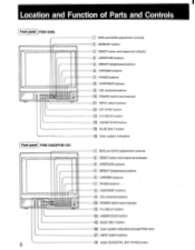
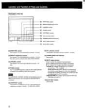
... EXT SYNC button 13 H-V DELAY button 1141 UNDER SCAN button 15 BLUE ONLY button 16 Color system indicators 1 BIAS and GAIN adjustment controls 13 1 RESET button and response indicator 141 APERTURE buttons 5 BRIGHT (brightness) buttons 6 CHROMA buttons 17 1 PHASE buttons 101 CONTRAST buttons 9 VOL (volume) buttons 1101 POWER switch and indicator 13 H-V DELAY button 1141 UNDER SCAN button 151 BLUE ONLY button 16 Color system indicators (except PVM-1341) 17 INPUT select buttons 18 ANALOG/DIGITAL (EXT SYNC)button Location and Function of Parts and Controls Front panel PVM...
... EXT SYNC button 13 H-V DELAY button 1141 UNDER SCAN button 15 BLUE ONLY button 16 Color system indicators 1 BIAS and GAIN adjustment controls 13 1 RESET button and response indicator 141 APERTURE buttons 5 BRIGHT (brightness) buttons 6 CHROMA buttons 17 1 PHASE buttons 101 CONTRAST buttons 9 VOL (volume) buttons 1101 POWER switch and indicator 13 H-V DELAY button 1141 UNDER SCAN button 151 BLUE ONLY button 16 Color system indicators (except PVM-1341) 17 INPUT select buttons 18 ANALOG/DIGITAL (EXT SYNC)button Location and Function of Parts and Controls Front panel PVM...
Operating Instructions
Page 7
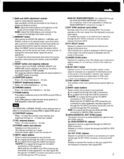
...: Adjust the white balance and contrast of analog RGB or digital RGB signals. 8 CONTRAST buttons Press + to turn the monitor off the red and green signals. The response indicator flashes when the above buttons or the RESET button is displayed near the center of ANALOG RGB/COMPONENT connectors on the sync signal from the displayed composite video signal. The indicator will be monitored. ANALOG RGB/COMPONENT: for underscanning. Ti H•V DELAY button Depress to make them purplish. The display size is pressed, the above operations. A blue signal...
...: Adjust the white balance and contrast of analog RGB or digital RGB signals. 8 CONTRAST buttons Press + to turn the monitor off the red and green signals. The response indicator flashes when the above buttons or the RESET button is displayed near the center of ANALOG RGB/COMPONENT connectors on the sync signal from the displayed composite video signal. The indicator will be monitored. ANALOG RGB/COMPONENT: for underscanning. Ti H•V DELAY button Depress to make them purplish. The display size is pressed, the above operations. A blue signal...
Operating Instructions
Page 8
... program to make them purplish. Location and Function of Parts and Controls Front panel PVM-134O U U fi) 0 0 0 2 19 APERTURE control 20 BRIGHT (brightness) control 21 CHROMA control 0 PHASE control 231 CONTRAST control 1241 VOL (volume) control 1251 POWER switch and indicator a INPUT select buttons 27 BLUE ONLY button 1191APERTURE control Turn toward + for more sharpness or toward - for a signal fed through the ANALOG RGB IN connector. 231CONTRAST control Turn toward + to be monitored. Note The APERTURE, CHROMA, PHASE control settings have no...
... program to make them purplish. Location and Function of Parts and Controls Front panel PVM-134O U U fi) 0 0 0 2 19 APERTURE control 20 BRIGHT (brightness) control 21 CHROMA control 0 PHASE control 231 CONTRAST control 1241 VOL (volume) control 1251 POWER switch and indicator a INPUT select buttons 27 BLUE ONLY button 1191APERTURE control Turn toward + for more sharpness or toward - for a signal fed through the ANALOG RGB IN connector. 231CONTRAST control Turn toward + to be monitored. Note The APERTURE, CHROMA, PHASE control settings have no...
Operating Instructions
Page 9
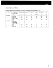
Model PVM-1344Q PVM-1342Q/ PVM-1341 PVM-1340 Input mode • LINE A, LINE B • Y/C • VTR Analog RGB Component • LINE A, LINE B • Y/C • VTR • Digital RGB • Analog RGB • LINE A, LINE B • Y/C • VTR Analog RGB APERTURE BRIGHT Yes Yes No Yes Yes Yes Yes Yes No Yes Yes Yes No Yes CHROMA Yes No Yes Yes No PHASE CONTRAST Yes _ (NTSC only) Yes No...
Model PVM-1344Q PVM-1342Q/ PVM-1341 PVM-1340 Input mode • LINE A, LINE B • Y/C • VTR Analog RGB Component • LINE A, LINE B • Y/C • VTR • Digital RGB • Analog RGB • LINE A, LINE B • Y/C • VTR Analog RGB APERTURE BRIGHT Yes Yes No Yes Yes Yes Yes Yes No Yes Yes Yes No Yes CHROMA Yes No Yes Yes No PHASE CONTRAST Yes _ (NTSC only) Yes No...
Operating Instructions
Page 10
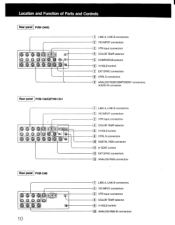
Location and Function of Parts and Controls Rear panel PVM-1344Q O0 (0) LINE A, LINE B connectors 2 Y/C-INPUT connectors _1 VTR input connectors T1 COLOR TEMP selector 05 COMPO/RGB selector LC • V HOLD control 1 EXT SYNC connectors 8 CTRL S connectors 1. ] ANALOG RGB/COMPONENT connectors, AUDIO IN connector Rear panel PVM-1342O/PVM-1341 O 006 O ie
Location and Function of Parts and Controls Rear panel PVM-1344Q O0 (0) LINE A, LINE B connectors 2 Y/C-INPUT connectors _1 VTR input connectors T1 COLOR TEMP selector 05 COMPO/RGB selector LC • V HOLD control 1 EXT SYNC connectors 8 CTRL S connectors 1. ] ANALOG RGB/COMPONENT connectors, AUDIO IN connector Rear panel PVM-1342O/PVM-1341 O 006 O ie
Operating Instructions
Page 11
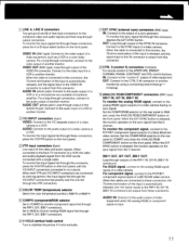
... the SYNC IN connector. To monitor the component signal, connect to the video output of another monitor by using a connecting cord (miniplug-,-.miniplug). 9 ANALOG RGB/COMPONENT connectors (BNC type) Ft/R-Y IN, G/Y IN, B/B-Y IN: To monitor the analog R/G/B signal, connect to the output of the APERTURE, BRIGHT, CHROMA, PHASE, CONTRAST and VOL control buttons. AUDIO IN: Connect to the analog RIG/B signal inputs of another monitor. For R/G/B signal, connect to the audio output of video equipment when the analog RIG/B or component signal is...
... the SYNC IN connector. To monitor the component signal, connect to the video output of another monitor by using a connecting cord (miniplug-,-.miniplug). 9 ANALOG RGB/COMPONENT connectors (BNC type) Ft/R-Y IN, G/Y IN, B/B-Y IN: To monitor the analog R/G/B signal, connect to the output of the APERTURE, BRIGHT, CHROMA, PHASE, CONTRAST and VOL control buttons. AUDIO IN: Connect to the analog RIG/B signal inputs of another monitor. For R/G/B signal, connect to the audio output of video equipment when the analog RIG/B or component signal is...
Operating Instructions
Page 12
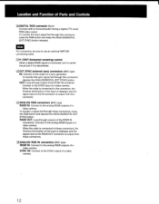
... use an optional SMF-520 connecting cable. 11 H CENT (horizontal centering) control When a digital R/G/B signal is monitored, turn to center the picture if it is output from this connector. 13 ANALOG RGB connectors (BNC type) R/G/B IN: Connect to the SYNC input of a video camera. SYNC IN: Connect to the analog R/G/B outputs of Parts and Controls 1101DIGITAL RGB connector (9-pin) Connect with a microcomputer having a digital (TTL level) RGB video output. When the cable is connected to these connectors, press the RGB button and depress the ANALOG/DIGITAL...
... use an optional SMF-520 connecting cable. 11 H CENT (horizontal centering) control When a digital R/G/B signal is monitored, turn to center the picture if it is output from this connector. 13 ANALOG RGB connectors (BNC type) R/G/B IN: Connect to the SYNC input of a video camera. SYNC IN: Connect to the analog R/G/B outputs of Parts and Controls 1101DIGITAL RGB connector (9-pin) Connect with a microcomputer having a digital (TTL level) RGB video output. When the cable is connected to these connectors, press the RGB button and depress the ANALOG/DIGITAL...
Operating Instructions
Page 13
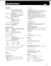
...) Raster size stability H: 1.0%, V: 1.5% High voltage regulation Audio output 0.6 W (Max.) CRT PVM-1344Q/PVM-1342Q: SMPTE-C (American-standard-phosphor) PVM-1341/PVM-1340: P-22 Chromacity coordinates (SMPTE C only) X Y Red Green Blue 0.630 0.310 0.155 0.340 0.595 0.070 _ (tolerance ±0.01) Color temperature 6,500 K19,300 K (+8MPCD), selectable AC regulation range 110 - 130 V AC, 50/60 Hz Power consumption Approx. 99 W Inputs For all models VIDEO IN: BNC connector AUIO...
...) Raster size stability H: 1.0%, V: 1.5% High voltage regulation Audio output 0.6 W (Max.) CRT PVM-1344Q/PVM-1342Q: SMPTE-C (American-standard-phosphor) PVM-1341/PVM-1340: P-22 Chromacity coordinates (SMPTE C only) X Y Red Green Blue 0.630 0.310 0.155 0.340 0.595 0.070 _ (tolerance ±0.01) Color temperature 6,500 K19,300 K (+8MPCD), selectable AC regulation range 110 - 130 V AC, 50/60 Hz Power consumption Approx. 99 W Inputs For all models VIDEO IN: BNC connector AUIO...
Operating Instructions
Page 14
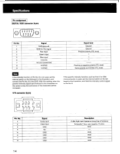
... ohms GND ---. Specifications Pin assignment DIGITAL RGB connector (9-pin) © ( O1OO2 O3OO4OO5o ) 6 789 Pin No. 1 2 3 4 5 6 7 8 9 Signal GND (ground) GND for the signal Red input Green input Blue input Intensity NC (no connection) H-SYNC V-SYNC Signal level Ground Ground Positive polarity (TTL level) t t t Positive or negative polarity (TTL level) Same polarity as that of Pin No. 6 is not used, set the internal switch on the Qd board to the B position, and connect the Pin No...
... ohms GND ---. Specifications Pin assignment DIGITAL RGB connector (9-pin) © ( O1OO2 O3OO4OO5o ) 6 789 Pin No. 1 2 3 4 5 6 7 8 9 Signal GND (ground) GND for the signal Red input Green input Blue input Intensity NC (no connection) H-SYNC V-SYNC Signal level Ground Ground Positive polarity (TTL level) t t t Positive or negative polarity (TTL level) Same polarity as that of Pin No. 6 is not used, set the internal switch on the Qd board to the B position, and connect the Pin No...

Operating Instructions
Page 15
Description 1 Vp-p, sync negative, 75 ohms 300 mVp-p, burst Delay time between Y and C: within 0±100 nsec., 75 ohms Ground Ground Press the switch inside this slot. YIC (VIC separate) INPUT connector (4-pin) 2 1 0 0 4 3 u 0 Pin No. 1 Y-input Signal 2 CHROMA sub-carrier-input 3 GND for Y-input 4 GND for CHROMA-input * Slot for internal switch Design and specifications subject to change without notice. The signal from Y/C-INPUT connector has priority over the one from VTR (8-pin) connector. 15
Description 1 Vp-p, sync negative, 75 ohms 300 mVp-p, burst Delay time between Y and C: within 0±100 nsec., 75 ohms Ground Ground Press the switch inside this slot. YIC (VIC separate) INPUT connector (4-pin) 2 1 0 0 4 3 u 0 Pin No. 1 Y-input Signal 2 CHROMA sub-carrier-input 3 GND for Y-input 4 GND for CHROMA-input * Slot for internal switch Design and specifications subject to change without notice. The signal from Y/C-INPUT connector has priority over the one from VTR (8-pin) connector. 15


