
(English:pg.58-108) Operating Instructions
Page 58
... Number: SONY PFM-42V1/PFM-42V1P/ PFM-42V1A Sony Electronics Inc. 16450 W. Record the model and serial numbers in the U.S.A. For customers in the spaces provided below. Sony Customer Information Services Center 1-800-222-7669 or http://www.sony.com/ Declaration of explosion if batteries are replaced by an incorrect type. This equipment generates, uses, and can radiate radio frequency energy and, if not installed and used batteries...
... Number: SONY PFM-42V1/PFM-42V1P/ PFM-42V1A Sony Electronics Inc. 16450 W. Record the model and serial numbers in the U.S.A. For customers in the spaces provided below. Sony Customer Information Services Center 1-800-222-7669 or http://www.sony.com/ Declaration of explosion if batteries are replaced by an incorrect type. This equipment generates, uses, and can radiate radio frequency energy and, if not installed and used batteries...

(English:pg.58-108) Operating Instructions
Page 59
...) Connecting the Speakers 15 (GB) Connecting the AC Power Cord 15 (GB) Connection Example 16 (GB) Using On-screen Menus 18 (GB) Operating Through Menus 18 (GB) GB Menu Guide 18 (GB) Watching the Picture 26 (GB) Switching the Input Signal 26 (GB) Input Signal, Picture Mode and Display Status Information 27 (GB) Switching the Display Mode 29 (GB) Energy Saving Function 29 (GB) Selecting Image Quality 30 (GB) Adjusting the Picture 30 (GB) Adjusting the Contrast, Brightness, Chroma...
...) Connecting the Speakers 15 (GB) Connecting the AC Power Cord 15 (GB) Connection Example 16 (GB) Using On-screen Menus 18 (GB) Operating Through Menus 18 (GB) GB Menu Guide 18 (GB) Watching the Picture 26 (GB) Switching the Input Signal 26 (GB) Input Signal, Picture Mode and Display Status Information 27 (GB) Switching the Display Mode 29 (GB) Energy Saving Function 29 (GB) Selecting Image Quality 30 (GB) Adjusting the Picture 30 (GB) Adjusting the Contrast, Brightness, Chroma...
(English:pg.58-108) Operating Instructions
Page 61
... further. • Unplug the unit from the wall outlet if it . is used for several days or more. • To disconnect the AC power cord, pull it out by qualified personnel before cleaning it is used in a location near the display. On installation • Allow adequate air circulation to equalize use video or imaging softwares to provide constant movement on the floor...
... further. • Unplug the unit from the wall outlet if it . is used for several days or more. • To disconnect the AC power cord, pull it out by qualified personnel before cleaning it is used in a location near the display. On installation • Allow adequate air circulation to equalize use video or imaging softwares to provide constant movement on the floor...
(English:pg.58-108) Operating Instructions
Page 62
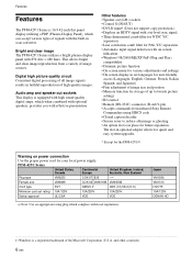
... local power supply. Bright and clear image The PFM-42V1 Series utilizes a bright plasma display panel with on power connection Use the proper power cord for future expansion. Features Features The PFM-42V1 Series is 16:9 42-inch flat panel display utilizing a PDP (Plasma Display Panel), which complies with effective presentation. This allows bright and clear image reproduction from infrared Sony Remote Commanders using SIRCS code • Closed caption decoder • Screen saver to twenty picture settings • ID control • Remote (RS-232C) connector (D-sub...
... local power supply. Bright and clear image The PFM-42V1 Series utilizes a bright plasma display panel with on power connection Use the proper power cord for future expansion. Features Features The PFM-42V1 Series is 16:9 42-inch flat panel display utilizing a PDP (Plasma Display Panel), which complies with effective presentation. This allows bright and clear image reproduction from infrared Sony Remote Commanders using SIRCS code • Closed caption decoder • Screen saver to twenty picture settings • ID control • Remote (RS-232C) connector (D-sub...

(English:pg.58-108) Operating Instructions
Page 64
... red in the standby mode. 3 ON indicator Lights up in a menu. 3 ENTER button Press to set your choice. 4 VOLUME +/- Press again to the standby mode. Location and Function of time is powered on the display unit. Note To protect the panel, a certain amount of Parts and Controls 1 (standby) Switch / Indicator Section Control Button Section (Top) 4 3 ON 2 STANDBY 1 123 4 MENU ENTER VOLUME 1 1 (standby) switch Press to power on . 4 Remote control detector Receives the signals...
... red in the standby mode. 3 ON indicator Lights up in a menu. 3 ENTER button Press to set your choice. 4 VOLUME +/- Press again to the standby mode. Location and Function of time is powered on the display unit. Note To protect the panel, a certain amount of Parts and Controls 1 (standby) Switch / Indicator Section Control Button Section (Top) 4 3 ON 2 STANDBY 1 123 4 MENU ENTER VOLUME 1 1 (standby) switch Press to power on . 4 Remote control detector Receives the signals...
(English:pg.58-108) Operating Instructions
Page 67
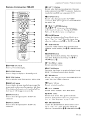
... signal input to the INPUT1 connectors. 6 INPUT2 button Press to select the signal input to the VIDEO connectors. Remote Commander RM-971 1 2 3 4 5 MUTING DISPLAY STBY ON POWER INPUT 1 INPUT 2 VIDEO OPTION qf 6 123 qg 456 qh 789 0 7 8 RGB/YUV S/VIDEO ASPECT MENU qj qk 9 ENTER 0 BRIGHT CHROMA ql qa H SHIFT V SHFT H SIZE VSIZE w; qs VOL CONTRAST wa qd ws ON SET OFF ID MODE wd PFM RM-971 1 POWER ON switch Press to mute the sound...
... signal input to the INPUT1 connectors. 6 INPUT2 button Press to select the signal input to the VIDEO connectors. Remote Commander RM-971 1 2 3 4 5 MUTING DISPLAY STBY ON POWER INPUT 1 INPUT 2 VIDEO OPTION qf 6 123 qg 456 qh 789 0 7 8 RGB/YUV S/VIDEO ASPECT MENU qj qk 9 ENTER 0 BRIGHT CHROMA ql qa H SHIFT V SHFT H SIZE VSIZE w; qs VOL CONTRAST wa qd ws ON SET OFF ID MODE wd PFM RM-971 1 POWER ON switch Press to mute the sound...

(English:pg.58-108) Operating Instructions
Page 68
Location and Function of Parts and Controls w; H SIZE button Adjusts the horizontal picture size. Press this button, then adjust the horizontal picture size with M/m or
Location and Function of Parts and Controls w; H SIZE button Adjusts the horizontal picture size. Press this button, then adjust the horizontal picture size with M/m or

(English:pg.58-108) Operating Instructions
Page 71
... each piece of equipment is turned off. • Use connecting cables suitable for the equipment to connect the speakers correctly. AC IN socket cover To remove the AC power cord After squeezing the AC plug holder and freeing it connects to the AC power cord. Connections 15 (GB) Then, attach the AC plug holder (supplied) to the AC IN socket cover. Connections Before you start • First make sure that came with...
... each piece of equipment is turned off. • Use connecting cables suitable for the equipment to connect the speakers correctly. AC IN socket cover To remove the AC power cord After squeezing the AC plug holder and freeing it connects to the AC power cord. Connections 15 (GB) Then, attach the AC plug holder (supplied) to the AC IN socket cover. Connections Before you start • First make sure that came with...

(English:pg.58-108) Operating Instructions
Page 74
Note Operation may differ in these operating instructions for menu operations. Remote Commander MENU Control button section ENTER MENU ENTER VOLUME Operation of the unit is explained in some cases since there is no The M/m and ENTER buttons on the Remote Commander have the same functions as the M/m and ENTER buttons on the display unit or the Remote Commander for the case of operation using the Remote Commander. Using On-screen Menus Using On-screen Menus Operating Through Menus Menu operating buttons Use the buttons on the display.
Note Operation may differ in these operating instructions for menu operations. Remote Commander MENU Control button section ENTER MENU ENTER VOLUME Operation of the unit is explained in some cases since there is no The M/m and ENTER buttons on the Remote Commander have the same functions as the M/m and ENTER buttons on the display unit or the Remote Commander for the case of operation using the Remote Commander. Using On-screen Menus Using On-screen Menus Operating Through Menus Menu operating buttons Use the buttons on the display.

(English:pg.58-108) Operating Instructions
Page 75
... 33 (GB). Color Temp. Gamma Correct. Adjust Sound menu You can make fine adjustment of the picture. Note You cannot adjust the following items when Picture Mode is set to Their Original Settings" on page 31 (GB). Chroma Press M/, to increase color saturation and press m/ < to decrease it. 19 (GB) Noise Reduct. Using On-screen Menus Dynamic Picture Enhances contrast by which image graininess and color noise are reduced...
... 33 (GB). Color Temp. Gamma Correct. Adjust Sound menu You can make fine adjustment of the picture. Note You cannot adjust the following items when Picture Mode is set to Their Original Settings" on page 31 (GB). Chroma Press M/, to increase color saturation and press m/ < to decrease it. 19 (GB) Noise Reduct. Using On-screen Menus Dynamic Picture Enhances contrast by which image graininess and color noise are reduced...

(English:pg.58-108) Operating Instructions
Page 76
... ze 00 H Size Adjust the horizontal picture size. The Auto Wide function is used for horizontal and vertical display, and automatically expands the picture to match the size and type of images. Wide Mode Switches the wide screen display to a wide screen image with a 16:9 aspect ratio, enabling the most appropriate display of different types of the picture. For details, see "Setting Auto Wide" on page 23 (GB). Press , to enlarge the horizontal size and press < to the Adjust Sound menu items. For...
... ze 00 H Size Adjust the horizontal picture size. The Auto Wide function is used for horizontal and vertical display, and automatically expands the picture to match the size and type of images. Wide Mode Switches the wide screen display to a wide screen image with a 16:9 aspect ratio, enabling the most appropriate display of different types of the picture. For details, see "Setting Auto Wide" on page 23 (GB). Press , to enlarge the horizontal size and press < to the Adjust Sound menu items. For...
(English:pg.58-108) Operating Instructions
Page 78
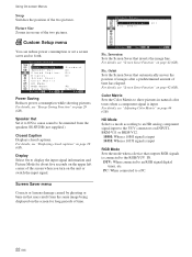
... connected to an RGB signal digital tuner, etc. Custom Setup menu You can reduce power consumption or set a screen saver and so forth. Speaker Out Set it to ON to cause sound to be emmited from the same image being displayed on page 29 (GB). Display Select On to the YUV connectors on INPUT1, BKM-V11 or BKM-V12. 1080I: When a 1080I signal is input 1035I: When a 1035I signal...
... connected to an RGB signal digital tuner, etc. Custom Setup menu You can reduce power consumption or set a screen saver and so forth. Speaker Out Set it to ON to cause sound to be emmited from the same image being displayed on page 29 (GB). Display Select On to the YUV connectors on INPUT1, BKM-V11 or BKM-V12. 1080I: When a 1080I signal is input 1035I: When a 1035I signal...
(English:pg.58-108) Operating Instructions
Page 79
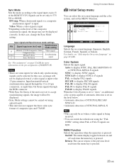
Input signal and Synchronous mode settings PIN Signal input over the D-sub Synchronous mode setting 13 13/14 2 480/60I, 575/50I Composite Video Composite Sync H Sync/V Sync Sync On Green Video signal Synchronizing signal See "Pin assignment" on and off each time the menu key is input to the 13 pin connector. Using On-screen Menus Initial Setup menu You can be displayed even if a video signal is pressed. 23 (GB) In that case, change the Sync Mode setting. Notes •...
Input signal and Synchronous mode settings PIN Signal input over the D-sub Synchronous mode setting 13 13/14 2 480/60I, 575/50I Composite Video Composite Sync H Sync/V Sync Sync On Green Video signal Synchronizing signal See "Pin assignment" on and off each time the menu key is input to the 13 pin connector. Using On-screen Menus Initial Setup menu You can be displayed even if a video signal is pressed. 23 (GB) In that case, change the Sync Mode setting. Notes •...

(English:pg.58-108) Operating Instructions
Page 80
... (GB). Clock Display Displays the currently set time on the display unit. E n d MENU Note When you set the index number, use the buttons on the screen when set to RGB. For details, see "Adjusting the time" on page 46 (GB). Remote menu This menu is automatically turned on page 40 (GB). Save Saves your settings. Using On-screen Menus Timer/Clock menu You can set the timer, adjust time, display the built-in the Picture/ Sound Control and Screen Control menus...
... (GB). Clock Display Displays the currently set time on the display unit. E n d MENU Note When you set the index number, use the buttons on the screen when set to RGB. For details, see "Adjusting the time" on page 46 (GB). Remote menu This menu is automatically turned on page 40 (GB). Save Saves your settings. Using On-screen Menus Timer/Clock menu You can set the timer, adjust time, display the built-in the Picture/ Sound Control and Screen Control menus...
(English:pg.58-108) Operating Instructions
Page 82
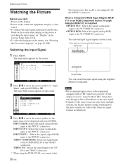
... model is installed OPTION YUV: Selects the signal (component) input to the INPUT1 connectors. INPUT2 DVI * : Selects the signal (digital RGB) input to On. • To select the language of the VIDEO connectors. * When using the supplied Remote Commander. Switching the Input Signal 1 Press MENU. VIDEO Y/C: Selects the signal input to the INPUT1 connectors. INPUT1 RGB: Selects the signal (analog RGB) input to the Y/C IN of the menus, see "Selecting the On-screen Language" on the screen. The main menu appears on the screen...
... model is installed OPTION YUV: Selects the signal (component) input to the INPUT1 connectors. INPUT2 DVI * : Selects the signal (digital RGB) input to On. • To select the language of the VIDEO connectors. * When using the supplied Remote Commander. Switching the Input Signal 1 Press MENU. VIDEO Y/C: Selects the signal input to the INPUT1 connectors. INPUT1 RGB: Selects the signal (analog RGB) input to the Y/C IN of the menus, see "Selecting the On-screen Language" on the screen. The main menu appears on the screen...

(English:pg.58-108) Operating Instructions
Page 83
... the DISPLAY button on the Remote Commander, regardless of the above . The factory default setting is switched. To disable this function, follow the steps below. 1 In the Custom Setup menu, press M/m to move the cursor (yellow) to "Off." The following menu appears on the screen. Watching the Picture 27 (GB) To display the information Set "Display" to "On" in step 2 above setting. Input Signal, Picture Mode and Display Status Information Input signal and Picture Mode information...
... the DISPLAY button on the Remote Commander, regardless of the above . The factory default setting is switched. To disable this function, follow the steps below. 1 In the Custom Setup menu, press M/m to move the cursor (yellow) to "Off." The following menu appears on the screen. Watching the Picture 27 (GB) To display the information Set "Display" to "On" in step 2 above setting. Input Signal, Picture Mode and Display Status Information Input signal and Picture Mode information...
(English:pg.58-108) Operating Instructions
Page 84
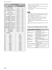
.... c) Mac (Macintosh) is component video. The selected input signal is a registered trademark of INPUT1 is set to component video. Y/C video input is NTSC. The selected input signal is selected for VIDEO. Actual on the INPUT1 connector. • If colors appear too light after inputting a DVD signal to PFM-42V1 series, adjust the "Chroma" setting in the Adjust Picture menu. • When the phase is set to RGB. Watching the Picture Preset input signals Signal name Color system or horizontal/ vertical frequency Computer signals 1 VGAa)-1 (VGA 350...
.... c) Mac (Macintosh) is component video. The selected input signal is a registered trademark of INPUT1 is set to component video. Y/C video input is NTSC. The selected input signal is selected for VIDEO. Actual on the INPUT1 connector. • If colors appear too light after inputting a DVD signal to PFM-42V1 series, adjust the "Chroma" setting in the Adjust Picture menu. • When the phase is set to RGB. Watching the Picture Preset input signals Signal name Color system or horizontal/ vertical frequency Computer signals 1 VGAa)-1 (VGA 350...

(English:pg.58-108) Operating Instructions
Page 102
... press the DISPLAY button on the screen. The following menu appears on the Remote Commander, the clock disappears, and the signal currently input and the Picture Mode appear. The following menu appears on the lower right corner of the second turns to power off . 46 (GB) When you must make further adjustments, or the setting must be exhausted. The setting for the minute is displayed undisturbed for...
... press the DISPLAY button on the screen. The following menu appears on the Remote Commander, the clock disappears, and the signal currently input and the Picture Mode appear. The following menu appears on the lower right corner of the second turns to power off . 46 (GB) When you must make further adjustments, or the setting must be exhausted. The setting for the minute is displayed undisturbed for...

(English:pg.58-108) Operating Instructions
Page 107
... INPUT2 connectors. 2) The PFM-42V1E and 42V1N are not equipped with VIDEO connectors. Specifications Specifications Video processing Preset signal See page 28 (GB). Sampling rate 13.5 MHz to 140 MHz Panel system AC-type Plasma Display Panel Display resolution 852 dots (horizontal) × 480 lines (vertical) 480 dots (horizontal) × 852 lines (vertical) (PFM-42V1P) Pixel pitch 1.08 (horizontal) × 1.08 (vertical) mm (1⁄32 × 1⁄32 inches) Picture size 920 (horizontal) × 518 (vertical) mm...
... INPUT2 connectors. 2) The PFM-42V1E and 42V1N are not equipped with VIDEO connectors. Specifications Specifications Video processing Preset signal See page 28 (GB). Sampling rate 13.5 MHz to 140 MHz Panel system AC-type Plasma Display Panel Display resolution 852 dots (horizontal) × 480 lines (vertical) 480 dots (horizontal) × 852 lines (vertical) (PFM-42V1P) Pixel pitch 1.08 (horizontal) × 1.08 (vertical) mm (1⁄32 × 1⁄32 inches) Picture size 920 (horizontal) × 518 (vertical) mm...
Marketing Specifications
Page 1
... bezel colors - New Connector Panel - 2 RGB/Component 15 pin Inputs - Showcasing a high resolution picture at 852 x 480 pixels and a stylish design, the PFM-42V1 plasma monitor is prohibited. The PFM-42V1 (42" viewable area, measured diagonally) monitor supports a new plasma panel with sizing adjustment • Supports The Real Digital Processing System Incorporating: - The units are subject to change without written permission is available in part without notice. Sony introduces the PFM-42V1/B and PFM-42V1/S PlasmaPro™ Flat Panel Display...
... bezel colors - New Connector Panel - 2 RGB/Component 15 pin Inputs - Showcasing a high resolution picture at 852 x 480 pixels and a stylish design, the PFM-42V1 plasma monitor is prohibited. The PFM-42V1 (42" viewable area, measured diagonally) monitor supports a new plasma panel with sizing adjustment • Supports The Real Digital Processing System Incorporating: - The units are subject to change without written permission is available in part without notice. Sony introduces the PFM-42V1/B and PFM-42V1/S PlasmaPro™ Flat Panel Display...


