
User Manual
Page 54
... B digital device, pursuant to Part 15 of the FCC Rules. This equipment has been tested and found to comply with Canadian ICES-003. WARNING Owner's Record The model and serial numbers are located on a circuit different from that to the following measures: • Reorient or relocate the receiving antenna. • Increase the separation between the equipment and receiver. • Connect the...
... B digital device, pursuant to Part 15 of the FCC Rules. This equipment has been tested and found to comply with Canadian ICES-003. WARNING Owner's Record The model and serial numbers are located on a circuit different from that to the following measures: • Reorient or relocate the receiving antenna. • Increase the separation between the equipment and receiver. • Connect the...
User Manual
Page 55
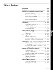
...) Control Button Section (Rear 8 (GB) Connector Panel 9 (GB) Remote Commander RM-42B 11 (GB) Caution 13 (GB) Connections 14 (GB) Connecting the AC Power Cord 14 (GB) Attaching the ferrite core (PFM-42B2/42B2E only 14 (GB) Connection Example 14 (GB) Using On-screen Menus 19 (GB) Operating Through Menus 19 (GB) GB Menu Guide 19 (GB) Watching the Picture 23 (GB) Switching the Input Signal 23 (GB) Switching the Display Mode 24...
...) Control Button Section (Rear 8 (GB) Connector Panel 9 (GB) Remote Commander RM-42B 11 (GB) Caution 13 (GB) Connections 14 (GB) Connecting the AC Power Cord 14 (GB) Attaching the ferrite core (PFM-42B2/42B2E only 14 (GB) Connection Example 14 (GB) Using On-screen Menus 19 (GB) Operating Through Menus 19 (GB) GB Menu Guide 19 (GB) Watching the Picture 23 (GB) Switching the Input Signal 23 (GB) Switching the Display Mode 24...
User Manual
Page 57
... of time, to display the same image on the screen for a long period of time, part of that may burn into the panel, use some striped or color irregularities may become less conspicuous, but once burn-in ) occurs, it is installed on the floor, be seen on the screen, or bright points (white, red, blue or green) may remain on surfaces (rugs, blankets, etc.) or near heat sources...
... of time, to display the same image on the screen for a long period of time, part of that may burn into the panel, use some striped or color irregularities may become less conspicuous, but once burn-in ) occurs, it is installed on the floor, be seen on the screen, or bright points (white, red, blue or green) may remain on surfaces (rugs, blankets, etc.) or near heat sources...
User Manual
Page 58
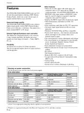
... using SIRCS code. • Vertical setup • Closed caption decoder • Screen saver to reduce afterimage or ghosting. The slot-in six languages for user-friendly access. (Languages: English, German, French, Italian, Spanish and Japanese) • Fine adjustment of image size and position • Memory function for quick and easy system upgrades. Features Features The PFM-42B1/42B2/42B1E/42B2E series are 16:9 42-inch flat panel displays utilizing a PDP (Plasma Display Panel...
... using SIRCS code. • Vertical setup • Closed caption decoder • Screen saver to reduce afterimage or ghosting. The slot-in six languages for user-friendly access. (Languages: English, German, French, Italian, Spanish and Japanese) • Fine adjustment of image size and position • Memory function for quick and easy system upgrades. Features Features The PFM-42B1/42B2/42B1E/42B2E series are 16:9 42-inch flat panel displays utilizing a PDP (Plasma Display Panel...
User Manual
Page 59
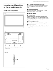
... 8 (GB). 3 Carrying handles 4 -AC IN socket Connect the supplied AC power cord to this socket and to install the stand (not supplied). 6 Connector panel For details on the connector panel, see "Control Button Section (Rear)" on page 9 (GB). Rear 2 3 4 5 The shaded areas shown in red and the display turns to the standby mode. 5 Stand installation hooks Use these hooks to a wall outlet. Once you connect the AC power cord, the STANDBY indicator lights up in the illustration above are...
... 8 (GB). 3 Carrying handles 4 -AC IN socket Connect the supplied AC power cord to this socket and to install the stand (not supplied). 6 Connector panel For details on the connector panel, see "Control Button Section (Rear)" on page 9 (GB). Rear 2 3 4 5 The shaded areas shown in red and the display turns to the standby mode. 5 Stand installation hooks Use these hooks to a wall outlet. Once you connect the AC power cord, the STANDBY indicator lights up in the illustration above are...
User Manual
Page 61
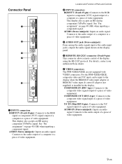
.... Connects to the audio output of a computer or a piece of video equipment. 3 AUDIO OUT jack (Stereo minijack) From among the audio signals input at the audio input jacks, outputs the audio signal shown on the display panel. 4 REMOTE (RS-232C) connector (D-sub 9-pin) This connector allows remote control of video equipment. Location and Function of Parts and Controls 2 INPUT2 connectors RGB/YUV (D-sub 15-pin): Connects to the composite video signal output of a piece of the display using...
.... Connects to the audio output of a computer or a piece of video equipment. 3 AUDIO OUT jack (Stereo minijack) From among the audio signals input at the audio input jacks, outputs the audio signal shown on the display panel. 4 REMOTE (RS-232C) connector (D-sub 9-pin) This connector allows remote control of video equipment. Location and Function of Parts and Controls 2 INPUT2 connectors RGB/YUV (D-sub 15-pin): Connects to the composite video signal output of a piece of the display using...

User Manual
Page 62
.... 1 VIDEO Connectors COMPOSITE IN (Video Input) connector (BNC): Connects to the Component (YUV) signal output connector. COMPOSITE OUT (Video Output) connector (BNC): Connects to the CONTROL S IN connector on the other device. 10 (GB) Location and Function of Parts and Controls Component Input Adaptor (with the VIDEO Input & Control S Adaptor BKM-B13. Video Input & Control S Adaptor BKM-B13 (Not supplied) The VIDEO connectors are Slot-in connectors. You can replace the VIDEO connectors with Control...
.... 1 VIDEO Connectors COMPOSITE IN (Video Input) connector (BNC): Connects to the Component (YUV) signal output connector. COMPOSITE OUT (Video Output) connector (BNC): Connects to the CONTROL S IN connector on the other device. 10 (GB) Location and Function of Parts and Controls Component Input Adaptor (with the VIDEO Input & Control S Adaptor BKM-B13. Video Input & Control S Adaptor BKM-B13 (Not supplied) The VIDEO connectors are Slot-in connectors. You can replace the VIDEO connectors with Control...

User Manual
Page 63
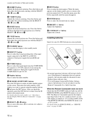
.... Network Adaptor BKM-B30NW (Not supplied) The VIDEO connectors are Slot-in the unit. 7 ASPECT button Changes the aspect ratio of the picture. 11 (GB) Press again to the Y/ C output connector of the display panel. COMPOSITE connector (Pinjack): Connect to the composite output connector of an image device. 2 PC card slot Install a LAN card or PC memory card as needed. 3 Ethernet connector Connect to turn on the display. 2 DISPLAY button Displays the input signal information...
.... Network Adaptor BKM-B30NW (Not supplied) The VIDEO connectors are Slot-in the unit. 7 ASPECT button Changes the aspect ratio of the picture. 11 (GB) Press again to the Y/ C output connector of the display panel. COMPOSITE connector (Pinjack): Connect to the composite output connector of an image device. 2 PC card slot Install a LAN card or PC memory card as needed. 3 Ethernet connector Connect to turn on the display. 2 DISPLAY button Displays the input signal information...
User Manual
Page 64
... this button and then adjust the horizontal picture size with the SELECT +M/-m button qj. 9 V SHIFT button Adjusts the vertical centering. qf S/VIDEO button Press to the previous menu level. For details about the index number, see "Operating a Specific Display With the Remote Commander" on the display panel, press to return to select the signal input from the COMPOSITE IN connector or Y/C IN connector from the ID mode to operate using the number buttons...
... this button and then adjust the horizontal picture size with the SELECT +M/-m button qj. 9 V SHIFT button Adjusts the vertical centering. qf S/VIDEO button Press to the previous menu level. For details about the index number, see "Operating a Specific Display With the Remote Commander" on the display panel, press to return to select the signal input from the COMPOSITE IN connector or Y/C IN connector from the ID mode to operate using the number buttons...

User Manual
Page 66
... equipment is turned off. • Use connecting cables suitable for the equipment to be fully inserted into the jacks. AC IN socket cover To remove the AC power cord After squeezing the AC plug holder and freeing it out by grasping the plug. Never pull the cable itself. • Refer to the instruction manual of the equipment to be connected. • The cable connectors should...
... equipment is turned off. • Use connecting cables suitable for the equipment to be fully inserted into the jacks. AC IN socket cover To remove the AC power cord After squeezing the AC plug holder and freeing it out by grasping the plug. Never pull the cable itself. • Refer to the instruction manual of the equipment to be connected. • The cable connectors should...

User Manual
Page 69
OUT IN Y/C IN CONTROL S VIDEO to Control S out to video output VCR, game machine, DVD player, etc. Connection Example: The Video Input & Control S Adaptor BKM-B13 (Not supplied) has been installed. Connections IN OUT COMPOSITE to Y/C IN or COMPOSITE IN to Control S in 17 (GB) The following shows a connection example where the Video Input & Control S Adaptor BKM-B13 (Not supplied) has been installed. For a connection example of the BKM-B30NW network adaptor (Not supplied), see the BKMB30NW instruction manual.
OUT IN Y/C IN CONTROL S VIDEO to Control S out to video output VCR, game machine, DVD player, etc. Connection Example: The Video Input & Control S Adaptor BKM-B13 (Not supplied) has been installed. Connections IN OUT COMPOSITE to Y/C IN or COMPOSITE IN to Control S in 17 (GB) The following shows a connection example where the Video Input & Control S Adaptor BKM-B13 (Not supplied) has been installed. For a connection example of the BKM-B30NW network adaptor (Not supplied), see the BKMB30NW instruction manual.

User Manual
Page 73
.... ql CLOSED CAPTION Displays closed captions" on page 38 (GB). CORNER: Sets the point of origin at the center of the display panel when the power is turned on -screen language (English, German, French, Italian, Spanish or Japanese). For details, see "Displaying closed captions. wk NETWORK ADAPTOR (PFM-42B2/42B2E only) Setting the Network Adaptor. SAVE SE L ECT S E T ENTER E N D MENU For details, see "Setting the SERIAL REMOTE" on page 33 (GB). wd POWER CONTROL Sets the...
.... ql CLOSED CAPTION Displays closed captions" on page 38 (GB). CORNER: Sets the point of origin at the center of the display panel when the power is turned on -screen language (English, German, French, Italian, Spanish or Japanese). For details, see "Displaying closed captions. wk NETWORK ADAPTOR (PFM-42B2/42B2E only) Setting the Network Adaptor. SAVE SE L ECT S E T ENTER E N D MENU For details, see "Setting the SERIAL REMOTE" on page 33 (GB). wd POWER CONTROL Sets the...
User Manual
Page 74
... power cord is based on the PFM-42B2E. If the message is displayed and the item flashes in a poorly ventilated location. OK: Normal NG: Unusual When the cooling fans are blocked or the display unit is normal. The display turns to the standby mode and the REMOTE ONLY mode is used for displaying the internal status of the OPERATION time. The STANDBY indicator on the 1 (standby) switch / indicator section also flashes...
... power cord is based on the PFM-42B2E. If the message is displayed and the item flashes in a poorly ventilated location. OK: Normal NG: Unusual When the cooling fans are blocked or the display unit is normal. The display turns to the standby mode and the REMOTE ONLY mode is used for displaying the internal status of the OPERATION time. The STANDBY indicator on the 1 (standby) switch / indicator section also flashes...

User Manual
Page 75
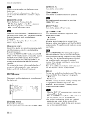
... can also switch the input signal using the Remote Commander. VIDEO COMPOSITE: Selects the audio and video signal input from the INPUT2 connectors when the input signal is installed.) The selected input signal appears on the display panel. Watching the Picture Before you start • Turn on the display. • Turn on the connected equipment and play a video source. • To display the input signal information on the screen when turning on the power or switching the input signal, set "DISPLAY" in the CONFIG (1/2) menu to ON...
... can also switch the input signal using the Remote Commander. VIDEO COMPOSITE: Selects the audio and video signal input from the INPUT2 connectors when the input signal is installed.) The selected input signal appears on the display panel. Watching the Picture Before you start • Turn on the display. • Turn on the connected equipment and play a video source. • To display the input signal information on the screen when turning on the power or switching the input signal, set "DISPLAY" in the CONFIG (1/2) menu to ON...

User Manual
Page 76
... hour is displayed in cyan. 4 Similarly, adjust the minute and press ENTER. Watching the Picture Switching the Display Mode Displaying closed captions 1 Press MENU. The CONFIG (1/2) menu appears on the display panel. 4 Select the caption type with v / V and press ENTER. TEXT1: Displays caption1 against a black background. 5 Press MENU. CAPT1: Displays caption1 over the picture. The time is shown in the upper-right corner of the minute is reset to "CLOSED CAPTION" and press...
... hour is displayed in cyan. 4 Similarly, adjust the minute and press ENTER. Watching the Picture Switching the Display Mode Displaying closed captions 1 Press MENU. The CONFIG (1/2) menu appears on the display panel. 4 Select the caption type with v / V and press ENTER. TEXT1: Displays caption1 against a black background. 5 Press MENU. CAPT1: Displays caption1 over the picture. The time is shown in the upper-right corner of the minute is reset to "CLOSED CAPTION" and press...
User Manual
Page 78
...) a) VGA is set to No.14), input it using a YUV signal. Notes • When inputting an HDTV signal, input the tri-level sync signal to the 2nd pin of INPUT1 is too light after inputting the DVD signal in the PFM-42B1/42B1E, adjust the color in the "CHROMA" setting in the PIC SIZE menu, or the picture might oscillate. • If the image color is set to RGB. INPUT1 YUV The signal mode of the...
...) a) VGA is set to No.14), input it using a YUV signal. Notes • When inputting an HDTV signal, input the tri-level sync signal to the 2nd pin of INPUT1 is too light after inputting the DVD signal in the PFM-42B1/42B1E, adjust the color in the "CHROMA" setting in the PIC SIZE menu, or the picture might oscillate. • If the image color is set to RGB. INPUT1 YUV The signal mode of the...

User Manual
Page 85
... automatically or manually. Storing the Current Setting 1 Press MENU. P I G MEMOR Y R EMO T E STATUS SE L ECT S E T ENTER E N D MENU (2) Adjust the dot phase or the total number of horizontal pixels with v / V and press ENTER. To restore PIXEL ADJUST menu items to their original settings In the PIXEL ADJUST menu, press v / V to move the cursor (B) to twenty input signals. The MEMORY menu appears on the display panel. Adjusting automatically (1) Select AUTO with v / V and...
... automatically or manually. Storing the Current Setting 1 Press MENU. P I G MEMOR Y R EMO T E STATUS SE L ECT S E T ENTER E N D MENU (2) Adjust the dot phase or the total number of horizontal pixels with v / V and press ENTER. To restore PIXEL ADJUST menu items to their original settings In the PIXEL ADJUST menu, press v / V to move the cursor (B) to twenty input signals. The MEMORY menu appears on the display panel. Adjusting automatically (1) Select AUTO with v / V and...
User Manual
Page 91
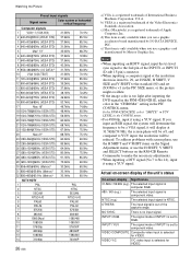
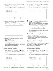
...; Input the sync signal again. • Press the 1 switch on the 1 (standby) switch / indicator section or the POWER ON switch on the display panel. Signal specification for using the power saving function The sync signal should be connected to the 13th pin of time until the change to power saving mode. OFF: The power saving function does not work. 5min: Changes to the power saving mode after five minutes if there is no input signal. The following menu appears...
...; Input the sync signal again. • Press the 1 switch on the 1 (standby) switch / indicator section or the POWER ON switch on the display panel. Signal specification for using the power saving function The sync signal should be connected to the 13th pin of time until the change to power saving mode. OFF: The power saving function does not work. 5min: Changes to the power saving mode after five minutes if there is no input signal. The following menu appears...

User Manual
Page 93
... pin of OFF TIME. The following menu appears on the display panel. The following menu appears on the display panel. Notes • The power saving function does not work when the signal is input from the VIDEO connectors. • If the sync signal is input. Controlling Power On/Off Automatically (Power Control Function) On Timer Function (PFM-42B2/ 42B2E only) 1 When the Step 4 screen in the ON/OFF TIMER function is displayed in light blue. ON / OF...
... pin of OFF TIME. The following menu appears on the display panel. The following menu appears on the display panel. Notes • The power saving function does not work when the signal is input from the VIDEO connectors. • If the sync signal is input. Controlling Power On/Off Automatically (Power Control Function) On Timer Function (PFM-42B2/ 42B2E only) 1 When the Step 4 screen in the ON/OFF TIMER function is displayed in light blue. ON / OF...
User Manual
Page 99
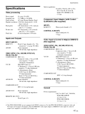
... (×2) 5 Vp-p General AUDIO OUT Stereo minijack 500 mVrms, high impedance Power requirements 100 V to 240 V AC, 50/60 Hz, REMOTE (RS-232C) D-sub 9-pin (×1) PFM-42B1/42B1E: 4.5 A to 1.8 A PFM-42B2/42B2E: 4.2 A to the display when the BKM-B10 video input adaptor or BKM-B13 video input & control S adaptor (not supplied) is installed in the display unit. 47 (GB) Specifications Specifications Video processing Preset signal See page 26...
... (×2) 5 Vp-p General AUDIO OUT Stereo minijack 500 mVrms, high impedance Power requirements 100 V to 240 V AC, 50/60 Hz, REMOTE (RS-232C) D-sub 9-pin (×1) PFM-42B1/42B1E: 4.5 A to 1.8 A PFM-42B2/42B2E: 4.2 A to the display when the BKM-B10 video input adaptor or BKM-B13 video input & control S adaptor (not supplied) is installed in the display unit. 47 (GB) Specifications Specifications Video processing Preset signal See page 26...


