Quick Start Guide
Page 2
...products are trademarks or registered trademarks of such software is subject to the model and serial numbers when you call your Sony VAIO® computer. Owner's Record The model number and serial number are subject to change without notice and may apply). Model Number:...policies will be completed by third parties. Financial services may require prior arrangements with this product. Sony, VAIO, the VAIO logo, VAIO Smart, Giga Pocket, MovieShaker, DVgate, Handycam, Memory Stick, the Memory Stick logo, Net MD, Network Walkman, OpenMG, MICROMV, SonicStage, ImageStation, ATRAC3, and i....
...products are trademarks or registered trademarks of such software is subject to the model and serial numbers when you call your Sony VAIO® computer. Owner's Record The model number and serial number are subject to change without notice and may apply). Model Number:...policies will be completed by third parties. Financial services may require prior arrangements with this product. Sony, VAIO, the VAIO logo, VAIO Smart, Giga Pocket, MovieShaker, DVgate, Handycam, Memory Stick, the Memory Stick logo, Net MD, Network Walkman, OpenMG, MICROMV, SonicStage, ImageStation, ATRAC3, and i....
Quick Start Guide
Page 16
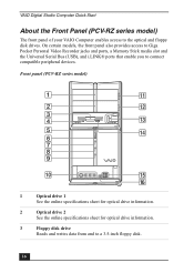
...access to Giga Pocket Personal Video Recorder jacks and ports, a Memory Stick media slot and the Universal Serial Bus (USB), and i.LINK® ports that enable you to a 3.5-inch floppy disk. 16 Front panel (PCV-RZ series model) 1 Optical drive 1 See the online specifications... sheet for optical drive information. 3 Floppy disk drive Reads and writes data from and to connect compatible peripheral devices. VAIO Digital Studio Computer Quick Start About the Front Panel (PCV-RZ series model) The front panel of your VAIO Computer enables access to the optical and floppy disk drives.
...access to Giga Pocket Personal Video Recorder jacks and ports, a Memory Stick media slot and the Universal Serial Bus (USB), and i.LINK® ports that enable you to a 3.5-inch floppy disk. 16 Front panel (PCV-RZ series model) 1 Optical drive 1 See the online specifications... sheet for optical drive information. 3 Floppy disk drive Reads and writes data from and to connect compatible peripheral devices. VAIO Digital Studio Computer Quick Start About the Front Panel (PCV-RZ series model) The front panel of your VAIO Computer enables access to the optical and floppy disk drives.

Quick Start Guide
Page 17
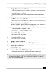
... data from and to a Memory Stick® media. About the Front Panel (PCV-RZ series model) 4 Floppy disk drive access indicator Light is green while reading and writing data from and to a floppy disk. 5 Power indicator Light is blue while the power is on. 6 Power switch Turns the computer on and off. 7 Stand...
... data from and to a Memory Stick® media. About the Front Panel (PCV-RZ series model) 4 Floppy disk drive access indicator Light is green while reading and writing data from and to a floppy disk. 5 Power indicator Light is blue while the power is on. 6 Power switch Turns the computer on and off. 7 Stand...
Quick Start Guide
Page 26
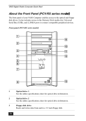
It also includes access to the Memory Stick media slot, Universal Serial Bus (USB), and i.LINK® ports to a 3.5-inch floppy disk. 26 Front panel (PCV-RX series model) 1 Optical drive 1 See the online specifications sheet for optical drive information. 2 Optical drive 2 See ... for optical drive information. 3 Floppy disk drive Reads and writes data from and to connect compatible peripheral devices. VAIO Digital Studio Computer Quick Start About the Front Panel (PCV-RX series model) The front panel of your VAIO Computer enables access to the optical and floppy disk drives.
It also includes access to the Memory Stick media slot, Universal Serial Bus (USB), and i.LINK® ports to a 3.5-inch floppy disk. 26 Front panel (PCV-RX series model) 1 Optical drive 1 See the online specifications sheet for optical drive information. 2 Optical drive 2 See ... for optical drive information. 3 Floppy disk drive Reads and writes data from and to connect compatible peripheral devices. VAIO Digital Studio Computer Quick Start About the Front Panel (PCV-RX series model) The front panel of your VAIO Computer enables access to the optical and floppy disk drives.
Quick Start Guide
Page 27
... amber while reading and writing data from and to the hard disk. 7 Power button and power indicator Turns the computer on/off. About the Front Panel (PCV-RX series model) 4 Floppy disk drive access indicator Light is green while reading and writing data from and to a floppy... Ejects a disc from Optical drive 1. 10 Optical drive 2 eject button Ejects a disc from Optical drive 2. 11 Memory Stick® media slot Reads and writes data from and to a Memory Stick media. 12 Floppy disk eject button Ejects a floppy disk. 13 Universal Serial Bus (USB 2.0) ports (4) Connections...
... amber while reading and writing data from and to the hard disk. 7 Power button and power indicator Turns the computer on/off. About the Front Panel (PCV-RX series model) 4 Floppy disk drive access indicator Light is green while reading and writing data from and to a floppy... Ejects a disc from Optical drive 1. 10 Optical drive 2 eject button Ejects a disc from Optical drive 2. 11 Memory Stick® media slot Reads and writes data from and to a Memory Stick media. 12 Floppy disk eject button Ejects a floppy disk. 13 Universal Serial Bus (USB 2.0) ports (4) Connections...
Quick Start Guide
Page 45
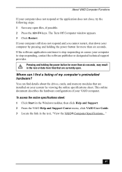
..., contact the software publisher or designated technical support provider. If the software application continues to stop responding or causes your VAIO computer. You can I find details about the drives, cards, and memory modules that are installed on your system by pressing and holding the power button for more than six seconds. This online...
..., contact the software publisher or designated technical support provider. If the software application continues to stop responding or causes your VAIO computer. You can I find details about the drives, cards, and memory modules that are installed on your system by pressing and holding the power button for more than six seconds. This online...
System Reference Manual
Page 2
... VAIO computer includes certain software versions or upgrades, and Internet services or offers that are trademarks or registered trademarks of license agreements enclosed with participating financial institutions. IN NO EVENT SHALL SONY ELECTRONICS INC. Software specifications are trademarks or registered trademarks of the Microsoft Corporation. Sony, VAIO, the VAIO logo, VAIO Smart, Giga Pocket, MovieShaker, DVgate, Handycam, Memory...
... VAIO computer includes certain software versions or upgrades, and Internet services or offers that are trademarks or registered trademarks of license agreements enclosed with participating financial institutions. IN NO EVENT SHALL SONY ELECTRONICS INC. Software specifications are trademarks or registered trademarks of the Microsoft Corporation. Sony, VAIO, the VAIO logo, VAIO Smart, Giga Pocket, MovieShaker, DVgate, Handycam, Memory...
System Reference Manual
Page 12
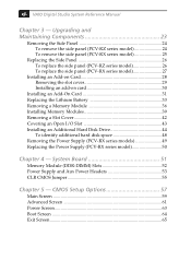
...Additional Hard Disk Drive 44 To identify additional hard disk space 48 Removing the Power Supply (PCV-RX series models 49 Replacing the Power Supply (PCV-RX series model 50 Chapter 4 - System Board 51 Memory Module (DDR-DIMM) Slots 52 Power Supply and Aux Power Headers 53 CLR CMOS Jumper ...55 Chapter 5 - CMOS Setup Options 57 Main Screen 59 Advanced Screen 61 Power Screen 63 Boot Screen 64 Exit Screen 65 xii VAIO Digital Studio...
...Additional Hard Disk Drive 44 To identify additional hard disk space 48 Removing the Power Supply (PCV-RX series models 49 Replacing the Power Supply (PCV-RX series model 50 Chapter 4 - System Board 51 Memory Module (DDR-DIMM) Slots 52 Power Supply and Aux Power Headers 53 CLR CMOS Jumper ...55 Chapter 5 - CMOS Setup Options 57 Main Screen 59 Advanced Screen 61 Power Screen 63 Boot Screen 64 Exit Screen 65 xii VAIO Digital Studio...
System Reference Manual
Page 13
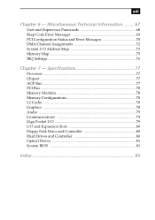
... 78 L2 Cache ...78 Graphics ...78 Audio ...79 Communications 79 Giga Pocket I/O 79 I /O Address Map 73 Memory Map 75 IRQ Settings 76 Chapter 7 - xiii Chapter 6 - Miscellaneous Technical Information ......... 67 User and Supervisor Passwords 68 Beep Code Error Messages 69 PCI Configuration Status ...
... 78 L2 Cache ...78 Graphics ...78 Audio ...79 Communications 79 Giga Pocket I/O 79 I /O Address Map 73 Memory Map 75 IRQ Settings 76 Chapter 7 - xiii Chapter 6 - Miscellaneous Technical Information ......... 67 User and Supervisor Passwords 68 Beep Code Error Messages 69 PCI Configuration Status ...
System Reference Manual
Page 17
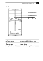
See online specifications sheet for details. Drives Identifying Components 3 Optical disc drive #1 Optical disc drive #2 Floppy disk drive Memory Stick media slot Drive Optical disc drive #1 Optical disc drive #2 Floppy disk drive Memory Stick® media slot Description See online specifications sheet for details. 3.5-inch, 1.44 MB. Accommodates Memory Stick media.
See online specifications sheet for details. Drives Identifying Components 3 Optical disc drive #1 Optical disc drive #2 Floppy disk drive Memory Stick media slot Drive Optical disc drive #1 Optical disc drive #2 Floppy disk drive Memory Stick® media slot Description See online specifications sheet for details. 3.5-inch, 1.44 MB. Accommodates Memory Stick media.
System Reference Manual
Page 38
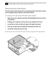
24 VAIO Digital Studio System Reference Manual Removing the Side Panel You must remove the side panel to access the system board, add-on these tabs and slide the side panel towards you. 5 Lift up on cards, power supply, battery, memory, and internal drives. To remove the side panel (PCV-...RZ series model) 1 Shut down your computer and turn off all peripheral devices, such as your printer. 2 Unplug your computer and disconnect any peripheral devices. 3 Locate the two tabs on the...
24 VAIO Digital Studio System Reference Manual Removing the Side Panel You must remove the side panel to access the system board, add-on these tabs and slide the side panel towards you. 5 Lift up on cards, power supply, battery, memory, and internal drives. To remove the side panel (PCV-...RZ series model) 1 Shut down your computer and turn off all peripheral devices, such as your printer. 2 Unplug your computer and disconnect any peripheral devices. 3 Locate the two tabs on the...
System Reference Manual
Page 47
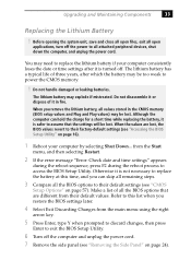
... explode if mistreated. Do not handle damaged or leaking batteries. Do not disassemble it or dispose of all the BIOS options to power the CMOS memory. ! Refer to this time, and you restore the BIOS settings later. 4 Select Exit Discarding Changes from the Start menu, and then selecting Restart. 2...Setup Utility" on page 24). The lithium battery may be lost . When you remove the lithium battery, all attached peripheral devices, shut down the computer, and unplug the power cord. Make a list of it is turned off the power to replace the battery at this list when you can hold...
... explode if mistreated. Do not handle damaged or leaking batteries. Do not disassemble it or dispose of all the BIOS options to power the CMOS memory. ! Refer to this time, and you restore the BIOS settings later. 4 Select Exit Discarding Changes from the Start menu, and then selecting Restart. 2...Setup Utility" on page 24). The lithium battery may be lost . When you remove the lithium battery, all attached peripheral devices, shut down the computer, and unplug the power cord. Make a list of it is turned off the power to replace the battery at this list when you can hold...
System Reference Manual
Page 50
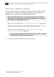
... memory module. 3 Locate the memory module you change the memory configuration or replace a bad module. 36 VAIO Digital Studio System Reference Manual Removing a Memory Module You may need to remove a memory module if you wish to remove. * Applicable to PCV-RX... models only. Before opening the system unit, save and close all open files, exit all open applications, turn off the power to all attached peripheral devices, shut down the computer...
... memory module. 3 Locate the memory module you change the memory configuration or replace a bad module. 36 VAIO Digital Studio System Reference Manual Removing a Memory Module You may need to remove a memory module if you wish to remove. * Applicable to PCV-RX... models only. Before opening the system unit, save and close all open files, exit all open applications, turn off the power to all attached peripheral devices, shut down the computer...
System Reference Manual
Page 51
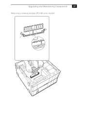
Upgrading and Maintaining Components 37 Removing a memory module (PCV-RZ series model)
Upgrading and Maintaining Components 37 Removing a memory module (PCV-RZ series model)
System Reference Manual
Page 52
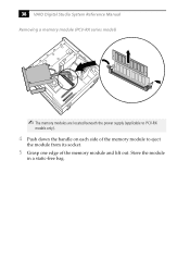
Store the module in a static-free bag. 38 VAIO Digital Studio System Reference Manual Removing a memory module (PCV-RX series model) ✍ The memory modules are located beneath the power supply (applicable to PCV-RX models only). 4 Push down the handle on each side of the memory module to eject the module from its socket. 5 Grasp one edge of the memory module and lift out.
Store the module in a static-free bag. 38 VAIO Digital Studio System Reference Manual Removing a memory module (PCV-RX series model) ✍ The memory modules are located beneath the power supply (applicable to PCV-RX models only). 4 Push down the handle on each side of the memory module to eject the module from its socket. 5 Grasp one edge of the memory module and lift out.
System Reference Manual
Page 53
... 5 Remove the power supply (see "Removing the Power Supply (PCV-RX series models)" on the configuration you wish to PCV-RX models only. Memory module configurations (MB)* DIMM1 0, 128, 256, 512 DIMM2 0, 128, 256, 512 * Your computer ships with more than 512 MB SDRAM depending on page 49).*... ! Hold the memory module only by a service technician. Your ...
... 5 Remove the power supply (see "Removing the Power Supply (PCV-RX series models)" on the configuration you wish to PCV-RX models only. Memory module configurations (MB)* DIMM1 0, 128, 256, 512 DIMM2 0, 128, 256, 512 * Your computer ships with more than 512 MB SDRAM depending on page 49).*... ! Hold the memory module only by a service technician. Your ...
System Reference Manual
Page 54
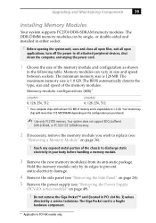
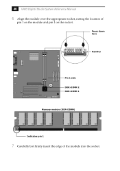
40 VAIO Digital Studio System Reference Manual 6 Align the module over the appropriate socket, noting the location of the module into the socket. Press down here Handles Pin 1 side DDR-DIMM 2 DDR-DIMM 1 Memory module (DDR-DIMM) 1 Indicates pin 1 7 Carefully but firmly insert the edge of pin 1 on the module and pin 1 on the socket.
40 VAIO Digital Studio System Reference Manual 6 Align the module over the appropriate socket, noting the location of the module into the socket. Press down here Handles Pin 1 side DDR-DIMM 2 DDR-DIMM 1 Memory module (DDR-DIMM) 1 Indicates pin 1 7 Carefully but firmly insert the edge of pin 1 on the module and pin 1 on the socket.
System Reference Manual
Page 55
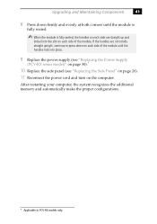
...computer, the system recognizes the additional memory and automatically make the proper configurations. * Applicable to press down firmly and evenly at both corners until the handles lock into the slot on each side are straight up and locked into place. 9 Replace the power supply (see "Replacing the Power Supply (PCV...until the module is fully seated. ✍ When the module is fully seated, the handles on the computer. If the handles are not totally straight upright, continue to PCV-RX models only. Upgrading and Maintaining Components 41 8 Press down on each side of the module.
...computer, the system recognizes the additional memory and automatically make the proper configurations. * Applicable to press down firmly and evenly at both corners until the handles lock into the slot on each side are straight up and locked into place. 9 Replace the power supply (see "Replacing the Power Supply (PCV...until the module is fully seated. ✍ When the module is fully seated, the handles on the computer. If the handles are not totally straight upright, continue to PCV-RX models only. Upgrading and Maintaining Components 41 8 Press down on each side of the module.
System Reference Manual
Page 63
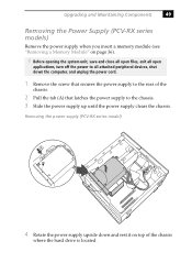
Removing the power supply (PCV-RX series model) A 4 Rotate the power supply upside down the computer, and unplug the power cord. 1 Remove the screw that secures the power supply to the rear of the chassis where the hard drive is located. ... peripheral devices, shut down and rest it on page 36). ! Upgrading and Maintaining Components 49 Removing the Power Supply (PCV-RX series models) Remove the power supply when you insert a memory module (see "Removing a Memory Module" on top of the chassis. 2 Pull the tab (A) that latches the power supply to the chassis. 3 Slide...
Removing the power supply (PCV-RX series model) A 4 Rotate the power supply upside down the computer, and unplug the power cord. 1 Remove the screw that secures the power supply to the rear of the chassis where the hard drive is located. ... peripheral devices, shut down and rest it on page 36). ! Upgrading and Maintaining Components 49 Removing the Power Supply (PCV-RX series models) Remove the power supply when you insert a memory module (see "Removing a Memory Module" on top of the chassis. 2 Pull the tab (A) that latches the power supply to the chassis. 3 Slide...
System Reference Manual
Page 65
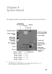
i.LINK Header (to front panel) Memory Processor CPU Fan Keyboard, Mouse Printer, Monitor, i.LINK USB3, USB4, S/P DIF Out USB5, USB6, Ethernet Mic In, Line In, Line Out CD-In Aux-In ...
i.LINK Header (to front panel) Memory Processor CPU Fan Keyboard, Mouse Printer, Monitor, i.LINK USB3, USB4, S/P DIF Out USB5, USB6, Ethernet Mic In, Line In, Line Out CD-In Aux-In ...


