
System Reference Manual
Page 2
...agreement. Model Numbers: PCV-RX462DS/ PCV-RX463DS/PCV-RX465DS/ PCV-RX470DS/PCV-RX480DS/ PCV-RX490TV Serial Number ii Updates and additions to software may not necessarily be identical to online service providers may require prior arrangements with this manual or the information ...VAIO® computer. This product contains software owned by Sony and licensed by the terms of Sony. Software specifications are located on the back of their respective owners. Sony, VAIO, the VAIO logo, VAIO Digital Studio, and i.LINK are trademarks or registered trademarks of your Sony ...
...agreement. Model Numbers: PCV-RX462DS/ PCV-RX463DS/PCV-RX465DS/ PCV-RX470DS/PCV-RX480DS/ PCV-RX490TV Serial Number ii Updates and additions to software may not necessarily be identical to online service providers may require prior arrangements with this manual or the information ...VAIO® computer. This product contains software owned by Sony and licensed by the terms of Sony. Software specifications are located on the back of their respective owners. Sony, VAIO, the VAIO logo, VAIO Digital Studio, and i.LINK are trademarks or registered trademarks of your Sony ...

System Reference Manual
Page 12
...Slot Cover 43 Covering an Open I/O Slot 44 Installing a 3.5-inch Internal Hard Disk Drive 45 To prepare a startup disk (PCV-RX490TV model only 45 To install a 3.5-inch internal hard disk drive (all models 46 To set up the new hard ...drive with the startup disk (PCV-RX490TV model only 49 To identify the additional hard disk space for Giga Pocket use (PCV-RX490TV model only 49 Removing the Power Supply 50 Replacing the Power Supply...Headers 72 CD-IN Header 73 AUX-IN Header 74 Video Header 75 xii VAIO Digital Studio™ System Reference Manual Chapter 3 -
...Slot Cover 43 Covering an Open I/O Slot 44 Installing a 3.5-inch Internal Hard Disk Drive 45 To prepare a startup disk (PCV-RX490TV model only 45 To install a 3.5-inch internal hard disk drive (all models 46 To set up the new hard ...drive with the startup disk (PCV-RX490TV model only 49 To identify the additional hard disk space for Giga Pocket use (PCV-RX490TV model only 49 Removing the Power Supply 50 Replacing the Power Supply...Headers 72 CD-IN Header 73 AUX-IN Header 74 Video Header 75 xii VAIO Digital Studio™ System Reference Manual Chapter 3 -

System Reference Manual
Page 14
xiv VAIO Digital Studio™ System Reference Manual Audio ...111 Communications 112 Giga Pocket I/O (PCV-RX490TV only 112 I/O and Expansion Slots 112 Floppy Disk Drive and Controller 113 Hard Drives and Controllers 113 Optical Drives 114 System BIOS 116 Index 117
xiv VAIO Digital Studio™ System Reference Manual Audio ...111 Communications 112 Giga Pocket I/O (PCV-RX490TV only 112 I/O and Expansion Slots 112 Floppy Disk Drive and Controller 113 Hard Drives and Controllers 113 Optical Drives 114 System BIOS 116 Index 117
System Reference Manual
Page 15
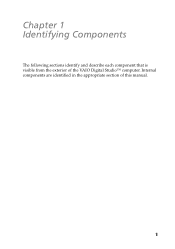
Chapter 1 Identifying Components The following sections identify and describe each component that is visible from the exterior of this manual. 1 Internal components are identified in the appropriate section of the VAIO Digital Studio™ computer.
Chapter 1 Identifying Components The following sections identify and describe each component that is visible from the exterior of this manual. 1 Internal components are identified in the appropriate section of the VAIO Digital Studio™ computer.

System Reference Manual
Page 16
2 VAIO Digital Studio™ System Reference Manual Front View All Models
2 VAIO Digital Studio™ System Reference Manual Front View All Models

System Reference Manual
Page 18
4 VAIO Digital Studio™ System Reference Manual ***Data on a CD-R/CD-ROM is read †† CD-R write CD-RW write‡‡ DVD-R write*** DVD-RW write CD-ROM drive CD-R/.... for CD-RW), or 12X, depending on the speed you select. ††† Data on a CD-R/CD-RW is written at the outermost track. PCV-RX490TV DVD-RW drive CD-ROM drive Floppy disk drive Drive Floppy disk drive DVD-RW drive* DVD-ROM read† DVD-RW/DVD-R read...
4 VAIO Digital Studio™ System Reference Manual ***Data on a CD-R/CD-ROM is read †† CD-R write CD-RW write‡‡ DVD-R write*** DVD-RW write CD-ROM drive CD-R/.... for CD-RW), or 12X, depending on the speed you select. ††† Data on a CD-R/CD-RW is written at the outermost track. PCV-RX490TV DVD-RW drive CD-ROM drive Floppy disk drive Drive Floppy disk drive DVD-RW drive* DVD-ROM read† DVD-RW/DVD-R read...
System Reference Manual
Page 20
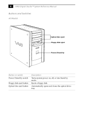
Automatically opens and closes the optical drive tray. Ejects a floppy disk. 6 VAIO Digital Studio™ System Reference Manual Buttons and Switches All Models Optical disc eject Floppy disk eject Power/Stand by Button or switch Power/Stand by switch Floppy disk eject button Optical disc eject button Description Turns system power on, off, or into Stand by mode.
Automatically opens and closes the optical drive tray. Ejects a floppy disk. 6 VAIO Digital Studio™ System Reference Manual Buttons and Switches All Models Optical disc eject Floppy disk eject Power/Stand by Button or switch Power/Stand by switch Floppy disk eject button Optical disc eject button Description Turns system power on, off, or into Stand by mode.

System Reference Manual
Page 22
A 6-pin i.LINK header can supply power from the computer to a 6-pin i.LINK device, use the i.LINK header on the back of the system. Connects to USB devices. * To connect to the device if the device also has a 6-pin i.LINK header. A 4-pin i.LINK header cannot supply power to a digital device that has a 4-pin i.LINK header. 8 VAIO Digital Studio™ System Reference Manual Connectors PCV-RX462DS/PCV-RX463DS/PCV-RX465DS/PCV-RX470DS/PCV-RX480DS USB3, USB4 i.LINK Connector i.LINK® (IEEE1394)* USB3, USB4 Description Connects to the device.
A 6-pin i.LINK header can supply power from the computer to a 6-pin i.LINK device, use the i.LINK header on the back of the system. Connects to USB devices. * To connect to the device if the device also has a 6-pin i.LINK header. A 4-pin i.LINK header cannot supply power to a digital device that has a 4-pin i.LINK header. 8 VAIO Digital Studio™ System Reference Manual Connectors PCV-RX462DS/PCV-RX463DS/PCV-RX465DS/PCV-RX470DS/PCV-RX480DS USB3, USB4 i.LINK Connector i.LINK® (IEEE1394)* USB3, USB4 Description Connects to the device.

System Reference Manual
Page 24
10 VAIO Digital Studio™ System Reference Manual Rear View All Models Mouse Keyboard USB1, USB2 Ethernet Serial Printer /Parallel i.LINK (IEEE394) Game/MIDI Headphones Line In Microphone Monitor Audio Out Video/S-video Out* Audio In Video/S-Video In* Line Power DVI VHF/UHF* Telephone** *Only in PCV-RX490TV Model ** In models with an HPNA modem, the telephone line jack does not exist.
10 VAIO Digital Studio™ System Reference Manual Rear View All Models Mouse Keyboard USB1, USB2 Ethernet Serial Printer /Parallel i.LINK (IEEE394) Game/MIDI Headphones Line In Microphone Monitor Audio Out Video/S-video Out* Audio In Video/S-Video In* Line Power DVI VHF/UHF* Telephone** *Only in PCV-RX490TV Model ** In models with an HPNA modem, the telephone line jack does not exist.

System Reference Manual
Page 26
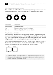
12 VAIO Digital Studio™ System Reference Manual All Models Icon Description Headphones LINE IN jack (audio) Microphone jack Monitor port Line jack (for telephone line from primary service jack) Telephone jack (for phone)* DVI (LCD) Monitor port * In models with an HPNA modem, the telephone jack does not exist. PCV-RX490TV Only Icon Description VHF/UHF port Audio In jack Audio Out jack Video/S-video In port Video/S-video Out port
12 VAIO Digital Studio™ System Reference Manual All Models Icon Description Headphones LINE IN jack (audio) Microphone jack Monitor port Line jack (for telephone line from primary service jack) Telephone jack (for phone)* DVI (LCD) Monitor port * In models with an HPNA modem, the telephone jack does not exist. PCV-RX490TV Only Icon Description VHF/UHF port Audio In jack Audio Out jack Video/S-video In port Video/S-video Out port
System Reference Manual
Page 28
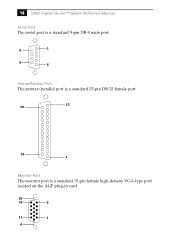
14 VAIO Digital Studio™ System Reference Manual Serial Port The serial port is a standard 9-pin DB-9 male port. 6 1 9 5 Printer/Parallel Port The printer/parallel port is a standard 25-pin DB-25 female port. 13 25 14 1 Monitor Port The monitor port is a standard 15-pin female high-density VGA-type port located on the AGP plug-in card. 10 15 5 11 1 6
14 VAIO Digital Studio™ System Reference Manual Serial Port The serial port is a standard 9-pin DB-9 male port. 6 1 9 5 Printer/Parallel Port The printer/parallel port is a standard 25-pin DB-25 female port. 13 25 14 1 Monitor Port The monitor port is a standard 15-pin female high-density VGA-type port located on the AGP plug-in card. 10 15 5 11 1 6
System Reference Manual
Page 30
... telephone equipment. Telephone and Line Jacks The telephone and line jacks are standard 3.5 mm stereo mini-jacks. Your computer will only have one RJ-11 female phone jack if you purchased. Headphones Line In Mic Connector Headphones Mic Line...computer to a telephone line that comes from the wall into the modem's telephone jack, and a telephone into the line jack, will not work correctly. Electret condenser microphone input. 1.0 Vrms (typical), 10 Kohm impedance. they are physically identical, but have different connections. 16 VAIO Digital Studio™ System Reference Manual...
... telephone equipment. Telephone and Line Jacks The telephone and line jacks are standard 3.5 mm stereo mini-jacks. Your computer will only have one RJ-11 female phone jack if you purchased. Headphones Line In Mic Connector Headphones Mic Line...computer to a telephone line that comes from the wall into the modem's telephone jack, and a telephone into the line jack, will not work correctly. Electret condenser microphone input. 1.0 Vrms (typical), 10 Kohm impedance. they are physically identical, but have different connections. 16 VAIO Digital Studio™ System Reference Manual...
System Reference Manual
Page 32
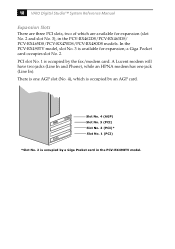
There is one jack (Line In). In the PCV-RX490TV model, slot No. 3 is occupied by an AGP card. A Lucent modem will have two jacks (Line In and Phone), while an HPNA modem has .... 4 (AGP) Slot No. 3 (PCI) Slot No. 2 (PCI)* Slot No. 1 (PCI) *Slot No. 2 is occupied by a Giga Pocket card in the PCV-RX462DS/PCV-RX463DS/ PCV-RX465DS/PCV-RX470DS/PCV-RX480DS models. 18 VAIO Digital Studio™ System Reference Manual Expansion Slots There are three PCI slots, two of which is available for expansion (slot No. 2 and slot No. 3), in the...
There is one jack (Line In). In the PCV-RX490TV model, slot No. 3 is occupied by an AGP card. A Lucent modem will have two jacks (Line In and Phone), while an HPNA modem has .... 4 (AGP) Slot No. 3 (PCI) Slot No. 2 (PCI)* Slot No. 1 (PCI) *Slot No. 2 is occupied by a Giga Pocket card in the PCV-RX462DS/PCV-RX463DS/ PCV-RX465DS/PCV-RX470DS/PCV-RX480DS models. 18 VAIO Digital Studio™ System Reference Manual Expansion Slots There are three PCI slots, two of which is available for expansion (slot No. 2 and slot No. 3), in the...

System Reference Manual
Page 36
... save and close all open files, and exit open applications. 1 Reboot your computer by selecting Shut Down... from the menu bar. Use the left and right...an item has a triangle ( ) to select a menu from the Start menu, then selecting Restart. 2 When the Sony logo appears, press F3. Once an item is another layer of options from which to select. 4 Once you reach ...(see "CMOS Setup Options" on page 85 for information on BIOS settings). ! 22 VAIO Digital Studio™ System Reference Manual Accessing the BIOS Setup Utility You must access the BIOS Setup Utility to make changes to select items...
... save and close all open files, and exit open applications. 1 Reboot your computer by selecting Shut Down... from the menu bar. Use the left and right...an item has a triangle ( ) to select a menu from the Start menu, then selecting Restart. 2 When the Sony logo appears, press F3. Once an item is another layer of options from which to select. 4 Once you reach ...(see "CMOS Setup Options" on page 85 for information on BIOS settings). ! 22 VAIO Digital Studio™ System Reference Manual Accessing the BIOS Setup Utility You must access the BIOS Setup Utility to make changes to select items...
System Reference Manual
Page 38
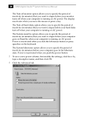
... hard disks option allows you to specify the period of inactivity (in minutes) that you want to elapse before your monitor turns off when your computer is reactivated when you push the power button. 3 To save a new power scheme, first modify the settings, click Save As, type a ...tab. The display reactivates when you to specify the period of inactivity (in minutes) before your computer goes in the hibernate state. Power is running on AC power. 24 VAIO Digital Studio™ System Reference Manual The Turn off monitor option allows you to specify the period of inactivity (in minutes) that...
... hard disks option allows you to specify the period of inactivity (in minutes) that you want to elapse before your monitor turns off when your computer is reactivated when you push the power button. 3 To save a new power scheme, first modify the settings, click Save As, type a ...tab. The display reactivates when you to specify the period of inactivity (in minutes) before your computer goes in the hibernate state. Power is running on AC power. 24 VAIO Digital Studio™ System Reference Manual The Turn off monitor option allows you to specify the period of inactivity (in minutes) that...
System Reference Manual
Page 42
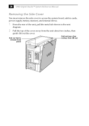
Pull out tab to access the system board, add-in cards, power supply, battery, memory, and internal drives. 1 From the rear of the unit, pull the metal tab shown in the next diagram. 2 Pull the top of the cover away from the unit about two inches, then gently lift out the cover. 28 VAIO Digital Studio™ System Reference Manual Removing the Side Cover You must remove the side cover to release front panel Pull out top a few inches, then lift out
Pull out tab to access the system board, add-in cards, power supply, battery, memory, and internal drives. 1 From the rear of the unit, pull the metal tab shown in the next diagram. 2 Pull the top of the cover away from the unit about two inches, then gently lift out the cover. 28 VAIO Digital Studio™ System Reference Manual Removing the Side Cover You must remove the side cover to release front panel Pull out top a few inches, then lift out
System Reference Manual
Page 44
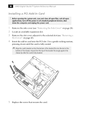
... the screw that the bottom of the bracket fits into the PCI slot. 30 VAIO Digital Studio™ System Reference Manual Installing a PCI Add-In Card ! Assure that the top of the chassis. Use a gentle rocking motion, pressing down the computer, and unplug the power cord. 1 Remove the side cover (see "Removing the Side Cover...
... the screw that the bottom of the bracket fits into the PCI slot. 30 VAIO Digital Studio™ System Reference Manual Installing a PCI Add-In Card ! Assure that the top of the chassis. Use a gentle rocking motion, pressing down the computer, and unplug the power cord. 1 Remove the side cover (see "Removing the Side Cover...
System Reference Manual
Page 46
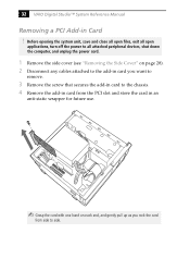
32 VAIO Digital Studio™ System Reference Manual Removing a PCI Add-in an anti-static wrapper for future use. ✍ Grasp the card with one hand on page 28). 2 Disconnect any cables attached ... the system unit, save and close all open files, exit all open applications, turn off the power to all attached peripheral devices, shut down the computer, and unplug the power cord. 1 Remove the side cover (see "Removing the Side Cover" on each end, and gently pull up as you rock the...
32 VAIO Digital Studio™ System Reference Manual Removing a PCI Add-in an anti-static wrapper for future use. ✍ Grasp the card with one hand on page 28). 2 Disconnect any cables attached ... the system unit, save and close all open files, exit all open applications, turn off the power to all attached peripheral devices, shut down the computer, and unplug the power cord. 1 Remove the side cover (see "Removing the Side Cover" on each end, and gently pull up as you rock the...
System Reference Manual
Page 48
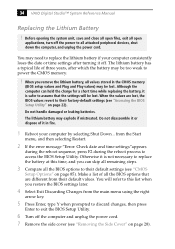
34 VAIO Digital Studio™ System Reference Manual Replacing the Lithium Battery ! When the values are different from their default values. Do...to this time, and you can hold the charge for a short time while replacing the battery, it off the computer and unplug the power cord. 7 Remove the side cover (see "Removing the Side Cover" on page 28). ...Enter, type Y when prompted to discard changes, then press Enter to all values stored in fire. 1 Reboot your computer consistently loses the date or time settings after which the battery may need to power the CMOS memory. ! When you...
34 VAIO Digital Studio™ System Reference Manual Replacing the Lithium Battery ! When the values are different from their default values. Do...to this time, and you can hold the charge for a short time while replacing the battery, it off the computer and unplug the power cord. 7 Remove the side cover (see "Removing the Side Cover" on page 28). ...Enter, type Y when prompted to discard changes, then press Enter to all values stored in fire. 1 Reboot your computer consistently loses the date or time settings after which the battery may need to power the CMOS memory. ! When you...
System Reference Manual
Page 50
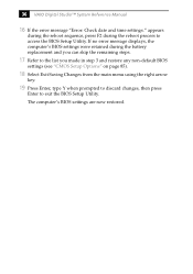
The computer's BIOS settings are now restored. 36 VAIO Digital Studio™ System Reference Manual 16 If the error message "Error: Check date and time settings." appears during the reboot sequence, press F2 during the battery replacement and you can ... key. 19 Press Enter, type Y when prompted to discard changes, then press Enter to access the BIOS Setup Utility. If no error message displays, the computer's BIOS settings were retained during the reboot process to exit the BIOS Setup Utility.
The computer's BIOS settings are now restored. 36 VAIO Digital Studio™ System Reference Manual 16 If the error message "Error: Check date and time settings." appears during the reboot sequence, press F2 during the battery replacement and you can ... key. 19 Press Enter, type Y when prompted to discard changes, then press Enter to access the BIOS Setup Utility. If no error message displays, the computer's BIOS settings were retained during the reboot process to exit the BIOS Setup Utility.


