
System Reference Manual
Page 12
... 63 Fan Headers 64 CD-In Header 65 Wake On LAN (WOL-CON) Header 66 AUX Audio Header 67 Configuration Jumper (CMOS CLR 68 xii VAIO® System Reference Manual Chapter 3 - Removing, Installing, and Replacing Components 23 Removing the Side Cover 24 Replacing the Side Cover 25 Installing a...Add-In Card 26 Removing a PCI Add-in Card 27 Installing an Add-On AGP Card 29 Replacing the Lithium Battery 31 Installing System Memory 34 Removing a Memory Module 37 Removing a Slot Cover 39 Covering an Open I/O Slot 40 Installing a 3.5-inch Internal Hard Disk Drive 41 Removing the Power ...
... 63 Fan Headers 64 CD-In Header 65 Wake On LAN (WOL-CON) Header 66 AUX Audio Header 67 Configuration Jumper (CMOS CLR 68 xii VAIO® System Reference Manual Chapter 3 - Removing, Installing, and Replacing Components 23 Removing the Side Cover 24 Replacing the Side Cover 25 Installing a...Add-In Card 26 Removing a PCI Add-in Card 27 Installing an Add-On AGP Card 29 Replacing the Lithium Battery 31 Installing System Memory 34 Removing a Memory Module 37 Removing a Slot Cover 39 Covering an Open I/O Slot 40 Installing a 3.5-inch Internal Hard Disk Drive 41 Removing the Power ...

System Reference Manual
Page 13
... 71 Chapter 6 - Specifications 91 Processor 91 Chipset ...91 PCI Bus ...91 AGP Bus ...91 DIMM Configurations 92 Memory Modules (DIMMs 92 L2 Cache ...92 Graphics ...92 Audio ...93 Communications 93 I /O Address Map 86 Memory Map 88 IRQ Settings 89 Chapter 8 - CMOS Setup Options 73 Main Screen 75 Advanced Screen 77 Power Screen...
... 71 Chapter 6 - Specifications 91 Processor 91 Chipset ...91 PCI Bus ...91 AGP Bus ...91 DIMM Configurations 92 Memory Modules (DIMMs 92 L2 Cache ...92 Graphics ...92 Audio ...93 Communications 93 I /O Address Map 86 Memory Map 88 IRQ Settings 89 Chapter 8 - CMOS Setup Options 73 Main Screen 75 Advanced Screen 77 Power Screen...

System Reference Manual
Page 38
Pull tab towards rear to access the system board, add-in cards, power supply, battery, memory, and internal drives. 1 From the rear of the unit, pull the metal tab shown in the next diagram. 2 Pull the top of the side cover away from the unit about two inches, then gently lift out the side cover. 24 VAIO® System Reference Manual Removing the Side Cover You must remove the side cover to release front panel Rotate top out a few inches, then lift out
Pull tab towards rear to access the system board, add-in cards, power supply, battery, memory, and internal drives. 1 From the rear of the unit, pull the metal tab shown in the next diagram. 2 Pull the top of the side cover away from the unit about two inches, then gently lift out the side cover. 24 VAIO® System Reference Manual Removing the Side Cover You must remove the side cover to release front panel Rotate top out a few inches, then lift out

System Reference Manual
Page 45
... this time, and you remove the lithium battery, all open applications, turn off the computer. ! The lithium battery has a typical life of all the BIOS options that the settings will refer to power the CMOS memory. ! Before opening the system unit, save and close all open files, exit all ...values stored in fire. 1 Reboot your computer consistently loses the date or time settings after which the battery may explode if ...
... this time, and you remove the lithium battery, all open applications, turn off the computer. ! The lithium battery has a typical life of all the BIOS options that the settings will refer to power the CMOS memory. ! Before opening the system unit, save and close all open files, exit all ...values stored in fire. 1 Reboot your computer consistently loses the date or time settings after which the battery may explode if ...
System Reference Manual
Page 48
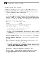
... 32, 64, 128, 256 * The PCV-RX450/PCV-RX460 ships with more than 128 MB SDRAM depending on page 45). 4 If necessary, remove the memory module you purchased. ✍ Use only 133 MHz FSB-supported memory. 34 VAIO® System Reference Manual Installing System Memory ! The BIOS automatically detects the type, ...speed of the memory module and configuration as shown in size and speed between sockets. Before opening the system unit, save and close all open files, exit all open applications, turn off the power to all attached peripheral devices, shut down the computer, and unplug the...
... 32, 64, 128, 256 * The PCV-RX450/PCV-RX460 ships with more than 128 MB SDRAM depending on page 45). 4 If necessary, remove the memory module you purchased. ✍ Use only 133 MHz FSB-supported memory. 34 VAIO® System Reference Manual Installing System Memory ! The BIOS automatically detects the type, ...speed of the memory module and configuration as shown in size and speed between sockets. Before opening the system unit, save and close all open files, exit all open applications, turn off the power to all attached peripheral devices, shut down the computer, and unplug the...

System Reference Manual
Page 49
... lock into the slot on the slot. If the handles are straight up and locked into place. Press down here Handles Pin 1 side DIMM 2 DIMM 1 Memory module (DIMM) 1 Indicates pin 1 8 Carefully but firmly insert the edge of the module into the slot. 9 Press down firmly and evenly at both corners until...
... lock into the slot on the slot. If the handles are straight up and locked into place. Press down here Handles Pin 1 side DIMM 2 DIMM 1 Memory module (DIMM) 1 Indicates pin 1 8 Carefully but firmly insert the edge of the module into the slot. 9 Press down firmly and evenly at both corners until...

System Reference Manual
Page 50
36 VAIO® System Reference Manual 10 Replace the power supply (see "Replacing the Power Supply" on page 46). 11 Replace the side cover (see "Replacing the Side Cover" on page 25). 12 Reconnect the power cord and turn on the computer. No further action is required. Your computer automatically recognizes the extra memory and will configure itself accordingly when you turn on the computer.
36 VAIO® System Reference Manual 10 Replace the power supply (see "Replacing the Power Supply" on page 46). 11 Replace the side cover (see "Replacing the Side Cover" on page 25). 12 Reconnect the power cord and turn on the computer. No further action is required. Your computer automatically recognizes the extra memory and will configure itself accordingly when you turn on the computer.

System Reference Manual
Page 51
... (see "Removing the Side Cover" on page 45). ! You need to remove a memory module if you wish to remove. Touch any exposed metal part of the chassis to all attached peripheral devices, shut down the computer, and unplug the power cord. 1 Remove the side cover (see "Removing the Power ...Supply" on page 24). ✍ The memory modules are located beneath the power supply. Before opening the system unit, save and close...
... (see "Removing the Side Cover" on page 45). ! You need to remove a memory module if you wish to remove. Touch any exposed metal part of the chassis to all attached peripheral devices, shut down the computer, and unplug the power cord. 1 Remove the side cover (see "Removing the Power ...Supply" on page 24). ✍ The memory modules are located beneath the power supply. Before opening the system unit, save and close...

System Reference Manual
Page 52
Store the module in a static-free bag. Push out Handles 5 Grasp one edge of the memory module to eject the module from its slot. 38 VAIO® System Reference Manual 4 Reach around each side of the power supply and push down the handle on each side of the memory module and lift out.
Store the module in a static-free bag. Push out Handles 5 Grasp one edge of the memory module to eject the module from its slot. 38 VAIO® System Reference Manual 4 Reach around each side of the power supply and push down the handle on each side of the memory module and lift out.

System Reference Manual
Page 59
Removing, Installing, and Replacing Components 45 Removing the Power Supply You remove the power supply when you insert a memory module (see "Installing System Memory" on top of the chassis. 2 Pull the tab (A) that secures the power supply to the chassis. A 3 Slide the power supply up until... the power supply clears the chassis. 4 Rotate the power supply upside down the computer, and unplug the power cord. 1 Remove the screw that...
Removing, Installing, and Replacing Components 45 Removing the Power Supply You remove the power supply when you insert a memory module (see "Installing System Memory" on top of the chassis. 2 Pull the tab (A) that secures the power supply to the chassis. A 3 Slide the power supply up until... the power supply clears the chassis. 4 Rotate the power supply upside down the computer, and unplug the power cord. 1 Remove the screw that...

System Reference Manual
Page 61
Processor Memory CPU Fan CPU Therm Keyboard, Mouse USB1, Ethernet Printer (top) Monitor, i.LINK i.LINK Header (to front panel) Serial (top) Mic in, Line in, Line out ...
Processor Memory CPU Fan CPU Therm Keyboard, Mouse USB1, Ethernet Printer (top) Monitor, i.LINK i.LINK Header (to front panel) Serial (top) Mic in, Line in, Line out ...

System Reference Manual
Page 64
DIMM1 DIMM2 50 VAIO® System Reference Manual Memory Module (DIMM) Slots Both sides of pin 1. The side with pin 1 has a small "1" to orient a DIMM correctly in the DIMM slot (a small triangle on the slot indicates pin 1). Be sure to the left of each Dual Inline Memory Module (DIMM) look very similar. Memory module (DIMM) 1 Indicates pin 1
DIMM1 DIMM2 50 VAIO® System Reference Manual Memory Module (DIMM) Slots Both sides of pin 1. The side with pin 1 has a small "1" to orient a DIMM correctly in the DIMM slot (a small triangle on the slot indicates pin 1). Be sure to the left of each Dual Inline Memory Module (DIMM) look very similar. Memory module (DIMM) 1 Indicates pin 1
System Reference Manual
Page 89
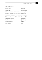
CMOS Setup Options 75 Main Screen System Time [00:00:00] System Date [01/01/2001] Primary Master (see "IDE Sub-Menus" on page 76) Primary Slave (see "IDE Sub-Menus" on page 76) Secondary Master (see "IDE Sub-Menus" on page 76) Secondary Slave (see "IDE Sub-Menus" on page 76) Supervisor Password [Disabled] User Password [Disabled] Installed Memory 128 MB BIOS Revision 1002
CMOS Setup Options 75 Main Screen System Time [00:00:00] System Date [01/01/2001] Primary Master (see "IDE Sub-Menus" on page 76) Primary Slave (see "IDE Sub-Menus" on page 76) Secondary Master (see "IDE Sub-Menus" on page 76) Secondary Slave (see "IDE Sub-Menus" on page 76) Supervisor Password [Disabled] User Password [Disabled] Installed Memory 128 MB BIOS Revision 1002

System Reference Manual
Page 95
Chapter 7 Miscellaneous Technical Information This chapter contains information on the following subjects: ❑ User and Supervisor password ❑ Beep code error messages ❑ PCI configuration status and error messages ❑ DMA channel assignments ❑ IRQ assignments ❑ System I/O address map ❑ Memory map ❑ PCI configuration space map 81
Chapter 7 Miscellaneous Technical Information This chapter contains information on the following subjects: ❑ User and Supervisor password ❑ Beep code error messages ❑ PCI configuration status and error messages ❑ DMA channel assignments ❑ IRQ assignments ❑ System I/O address map ❑ Memory map ❑ PCI configuration space map 81

System Reference Manual
Page 98
...Cleared CMOS Data Invalid, CMOS Cleared Parallel Port Resource Conflict PCI Error Log is Full PCI I/O Port Conflict PCI IRQ Conflict PCI Memory Conflict Primary Boot Device Not Found Primary IDE Controller Resource Conflict Primary Input Device Not Found Primary Output Device Not Found Secondary IDE ...mouse, or other , if input is redirected) could not be found . Two devices requested the same resource, resulting in a conflict. 84 VAIO® System Reference Manual PCI Configuration Status and Error Messages The following is a list of status and error messages that is already in use.
...Cleared CMOS Data Invalid, CMOS Cleared Parallel Port Resource Conflict PCI Error Log is Full PCI I/O Port Conflict PCI IRQ Conflict PCI Memory Conflict Primary Boot Device Not Found Primary IDE Controller Resource Conflict Primary Input Device Not Found Primary Output Device Not Found Secondary IDE ...mouse, or other , if input is redirected) could not be found . Two devices requested the same resource, resulting in a conflict. 84 VAIO® System Reference Manual PCI Configuration Status and Error Messages The following is a list of status and error messages that is already in use.

System Reference Manual
Page 99
The Microsoft® Windows® Me operating system reassigns resources to best meet the needs of a particular configuration. DMA Channel 2 4 Default Assignment Standard floppy disk controller Direct memory access controller Miscellaneous Technical Information 85 DMA Channel Assignments This shows the factory default values.
The Microsoft® Windows® Me operating system reassigns resources to best meet the needs of a particular configuration. DMA Channel 2 4 Default Assignment Standard floppy disk controller Direct memory access controller Miscellaneous Technical Information 85 DMA Channel Assignments This shows the factory default values.

System Reference Manual
Page 102
88 VAIO® System Reference Manual Memory Map Address range 00000000h-0009FFFFh 000A0000h-000AFFFFh 000B0000h-000BFFFFh 000C0000h-000CBFFFh 000F0000h-000FFFFFh 00100000h-07FFFFFFh E880000h-E8803FFFh E9000000h-E90007FFh E9800000h-E98000FFh E5000000h-E5000FFFh E5800000h-E5800FFFh ...
88 VAIO® System Reference Manual Memory Map Address range 00000000h-0009FFFFh 000A0000h-000AFFFFh 000B0000h-000BFFFFh 000C0000h-000CBFFFh 000F0000h-000FFFFFh 00100000h-07FFFFFFh E880000h-E8803FFFh E9000000h-E90007FFh E9800000h-E98000FFh E5000000h-E5000FFFh E5800000h-E5800FFFh ...
System Reference Manual
Page 106
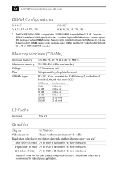
... 128 MB PC-133 SDRAM (133 MHz) 512 MB (256 MB in either socket. Computer SDRAM is unbuffered DIMM, specification Rev. 1.0 or later. Memory size can be installed in each socket) 3.3 V memory only 168-pins with gold-plated contacts PC-133, 60 ns, unrestricted CAS latency 2, ...-interlaced 256 colors (8 bits) Up to 512 MB. 92 VAIO® System Reference Manual DIMM Configurations DIMM1* 0, 8, 16, 32, 64, 128, 256 DIMM2* 0, 8, 16, 32, 64, 128, 256 * The PCV-RX450/PCV-RX460 is shipped with system memory (16 MB) Resolution (displayed resolution depends on the video monitor...
... 128 MB PC-133 SDRAM (133 MHz) 512 MB (256 MB in either socket. Computer SDRAM is unbuffered DIMM, specification Rev. 1.0 or later. Memory size can be installed in each socket) 3.3 V memory only 168-pins with gold-plated contacts PC-133, 60 ns, unrestricted CAS latency 2, ...-interlaced 256 colors (8 bits) Up to 512 MB. 92 VAIO® System Reference Manual DIMM Configurations DIMM1* 0, 8, 16, 32, 64, 128, 256 DIMM2* 0, 8, 16, 32, 64, 128, 256 * The PCV-RX450/PCV-RX460 is shipped with system memory (16 MB) Resolution (displayed resolution depends on the video monitor...

System Reference Manual
Page 111
See memory module display, power management 19 disposal of discs 3, 95 CMOS - See lithium battery beep codes 83 BIOS setup utility 18 advanced screen 77 boot screen ...-In connector 65 CD-RW drive location of 3 performance of lithium battery vii DMA channel assignments 85 97 See SERIAL connector communications, specifications 93 computer lithium battery vii computer safety information ii configuration jumper, CMOS Clear 68 configuring BIOS setup utility 18 power management 19 connectors 4-pin on modem card 70, 71...
See memory module display, power management 19 disposal of discs 3, 95 CMOS - See lithium battery beep codes 83 BIOS setup utility 18 advanced screen 77 boot screen ...-In connector 65 CD-RW drive location of 3 performance of lithium battery vii DMA channel assignments 85 97 See SERIAL connector communications, specifications 93 computer lithium battery vii computer safety information ii configuration jumper, CMOS Clear 68 configuring BIOS setup utility 18 power management 19 connectors 4-pin on modem card 70, 71...

System Reference Manual
Page 112
...disk drive, connector 49 front panel header 48 front view 2 buttons and switches 5 connectors 6, 7 drives 3 indicators 6 G graphics controller - See system memory memory module connector 50 removing 37 specifications for 93 expansion slots - See slots F fan connectors 64 CPU-FAN 64 PWR-FAN 64 fax card - See I... 61 MIC 13, 61 MONITOR 12 MOUSE 11 PRINTER 12 SERIAL 11 TELEPHONE 13 USB 11, 55 I /O address map and memory map memory - 98 VAIO® System Reference Manual drives IDE connectors 53 installing additional 3.5-inch drive 41 DVD-ROM drive performance of 9 IDE connectors 53 IEEE1394...
...disk drive, connector 49 front panel header 48 front view 2 buttons and switches 5 connectors 6, 7 drives 3 indicators 6 G graphics controller - See system memory memory module connector 50 removing 37 specifications for 93 expansion slots - See slots F fan connectors 64 CPU-FAN 64 PWR-FAN 64 fax card - See I... 61 MIC 13, 61 MONITOR 12 MOUSE 11 PRINTER 12 SERIAL 11 TELEPHONE 13 USB 11, 55 I /O address map and memory map memory - 98 VAIO® System Reference Manual drives IDE connectors 53 installing additional 3.5-inch drive 41 DVD-ROM drive performance of 9 IDE connectors 53 IEEE1394...


