Online Help Center (VAIO User Guide)
Page 59
... by accessing the Sony VAIO Direct Web site (http://vaio.sonystyle.com), or by the 6-pin i.LINK port cannot exceed 6 watts. i.LINK (IEEE1394) Compatibility Your VAIO computer may vary, depending on operating conditions and proper connection. A 4-pin i.LINK port cannot supply power to 12V. A... i.LINK ports. Please refer to the documentation that a product contains an IEEE1394 connection. Page 59 Sony computer supplies, accessories, and peripherals can : supply power from your computer: VMC-IL4415, VMC-IL4435, VMC-IL4615, VMC-IL4635, VMC-IL6615, and VMC-IL6635. All products...
... by accessing the Sony VAIO Direct Web site (http://vaio.sonystyle.com), or by the 6-pin i.LINK port cannot exceed 6 watts. i.LINK (IEEE1394) Compatibility Your VAIO computer may vary, depending on operating conditions and proper connection. A 4-pin i.LINK port cannot supply power to 12V. A... i.LINK ports. Please refer to the documentation that a product contains an IEEE1394 connection. Page 59 Sony computer supplies, accessories, and peripherals can : supply power from your computer: VMC-IL4415, VMC-IL4435, VMC-IL4615, VMC-IL4635, VMC-IL6615, and VMC-IL6635. All products...
Online Help Center (VAIO User Guide)
Page 80
... including incompatible or conflicting drivers, damaged files, or non-responsive hardware. The Windows operating system may result in standby mode. The VAIO Help and Support dialog box appears. 2. Follow the onscreen instructions according to recov er applications that it is not in the Windows...recov er driv ers that the monitor is plugged into a power strip or Uninterruptible Power Supply (UPS), make sure the power strip or UPS is turned on the front panel of the dialog box. 3. Save any open . The Turn Off Computer window appears. 3. Click Start in the floppy disk drive...
... including incompatible or conflicting drivers, damaged files, or non-responsive hardware. The Windows operating system may result in standby mode. The VAIO Help and Support dialog box appears. 2. Follow the onscreen instructions according to recov er applications that it is not in the Windows...recov er driv ers that the monitor is plugged into a power strip or Uninterruptible Power Supply (UPS), make sure the power strip or UPS is turned on the front panel of the dialog box. 3. Save any open . The Turn Off Computer window appears. 3. Click Start in the floppy disk drive...
Online Help Center (VAIO User Guide)
Page 87
... your equipment, refer the repair or replacement of the power supply to qualified personnel only. To remove power from the system, you will not be using the computer for a long time. Before touching anything inside the computer, turn off and let it out by the plug...electrical storm. If you may result in the power supply. This device contains both a surge protector and a battery backup. The battery backup safeguards your computer from different supply lines may want to your computer caused by sudden power surges such as copying machines or shredders. You...
... your equipment, refer the repair or replacement of the power supply to qualified personnel only. To remove power from the system, you will not be using the computer for a long time. Before touching anything inside the computer, turn off and let it out by the plug...electrical storm. If you may result in the power supply. This device contains both a surge protector and a battery backup. The battery backup safeguards your computer from different supply lines may want to your computer caused by sudden power surges such as copying machines or shredders. You...

Online Help Center (VAIO User Guide)
Page 88
... to your equipment, refer the repair or replacement of the power supply to open the power supply. To remove power from the system, you live in the power supply. There are no user-serviceable parts in an area that experiences frequent power fluctuations, you will not be using the computer for a long time. Before touching anything inside the...
... to your equipment, refer the repair or replacement of the power supply to open the power supply. To remove power from the system, you live in the power supply. There are no user-serviceable parts in an area that experiences frequent power fluctuations, you will not be using the computer for a long time. Before touching anything inside the...
Online Help Center (VAIO User Guide)
Page 108
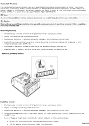
..., remove any peripheral devices. 3. Note: You can purchase additional memory modules, accessories, and peripheral equipment from the chassis. Unplug your Sony computer, see Removing memory 1. To Install Memory The preinstalled memory configuration may have memory modules already installed. For memory upgrades, use only 2.5V... memory in your printer. 2. Grasp one edge of the module to the chassis. Pull the tab that releases the power supply from your computer and any cables, add-on each side of the DIMM and lift it from the slot. 6. See To Remove the Side...
..., remove any peripheral devices. 3. Note: You can purchase additional memory modules, accessories, and peripheral equipment from the chassis. Unplug your Sony computer, see Removing memory 1. To Install Memory The preinstalled memory configuration may have memory modules already installed. For memory upgrades, use only 2.5V... memory in your printer. 2. Grasp one edge of the module to the chassis. Pull the tab that releases the power supply from your computer and any cables, add-on each side of the DIMM and lift it from the slot. 6. See To Remove the Side...
Online Help Center (VAIO User Guide)
Page 109
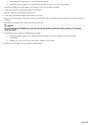
... the DIMM slot, move the end latches slightly outward to hold the module in place. 10. Replace the side panel. Slide the power supply unit up until the tab snaps into position to relieve pressure. Firmly insert the bottom edge of the chassis. 5. Locate the notches on cards ... The module clicks into the slot. 9. Press down position and rest it into the chassis until it clears the chassis. Rotate the power supply to an upside down evenly against the upper corners of the DIMM. 7. Reinstall any components or add-on the bottom edge of the DIMM. Align...
... the DIMM slot, move the end latches slightly outward to hold the module in place. 10. Replace the side panel. Slide the power supply unit up until the tab snaps into position to relieve pressure. Firmly insert the bottom edge of the chassis. 5. Locate the notches on cards ... The module clicks into the slot. 9. Press down position and rest it into the chassis until it clears the chassis. Rotate the power supply to an upside down evenly against the upper corners of the DIMM. 7. Reinstall any components or add-on the bottom edge of the DIMM. Align...
System Reference Manual
Page 10
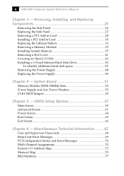
... Channel Assignments 72 System I /O Slot 42 Installing a 3.5-inch Internal Hard Disk Drive 43 To identify additional hard disk space 47 Removing the Power Supply 48 Replacing the Power Supply 49 Chapter 4 - Removing, Installing, and Replacing Components 25 Removing the Side Panel 26 Replacing the Side Panel 27 Removing a PCI Add-in... 41 Covering an Open I /O Address Map 73 Memory Map 75 IRQ Summary 77 CMOS Setup Options 57 Main Screen 59 Advanced Screen 61 Power Screen 64 Boot Screen 65 Exit Screen 66 Chapter 6 - x VAIO MX Computer System Reference Manual Chapter 3 -
... Channel Assignments 72 System I /O Slot 42 Installing a 3.5-inch Internal Hard Disk Drive 43 To identify additional hard disk space 47 Removing the Power Supply 48 Replacing the Power Supply 49 Chapter 4 - Removing, Installing, and Replacing Components 25 Removing the Side Panel 26 Replacing the Side Panel 27 Removing a PCI Add-in... 41 Covering an Open I /O Address Map 73 Memory Map 75 IRQ Summary 77 CMOS Setup Options 57 Main Screen 59 Advanced Screen 61 Power Screen 64 Boot Screen 65 Exit Screen 66 Chapter 6 - x VAIO MX Computer System Reference Manual Chapter 3 -
System Reference Manual
Page 35
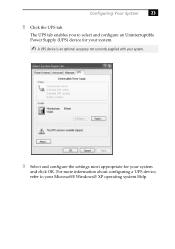
For more information about configuring a UPS device, refer to select and configure an Uninterruptible Power Supply (UPS) device for your system. ✍ A UPS device is an optional accessory not currently supplied with your system. 9 Select and configure the settings most appropriate for your Microsoft® Windows® XP operating system Help. The UPS tab enables you to your system and click OK. Configuring Your System 23 8 Click the UPS tab.
For more information about configuring a UPS device, refer to select and configure an Uninterruptible Power Supply (UPS) device for your system. ✍ A UPS device is an optional accessory not currently supplied with your system. 9 Select and configure the settings most appropriate for your Microsoft® Windows® XP operating system Help. The UPS tab enables you to your system and click OK. Configuring Your System 23 8 Click the UPS tab.

System Reference Manual
Page 41
... the card with one hand on the card. As a precaution, touch any exposed metal part on the metal chassis (preferably the metal part on the power supply) before handling an add-in card to side. ! Removing, Installing, and Replacing Components 29 5 Remove the add-in card from side to discharge any components...
... the card with one hand on the card. As a precaution, touch any exposed metal part on the metal chassis (preferably the metal part on the power supply) before handling an add-in card to side. ! Removing, Installing, and Replacing Components 29 5 Remove the add-in card from side to discharge any components...
System Reference Manual
Page 47
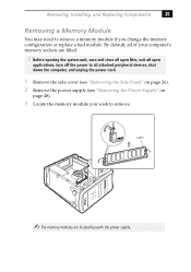
Before opening the system unit, save and close all open files, exit all open applications, turn off the power to remove. Latch ✍ The memory modules are filled. ! Removing, Installing, and Replacing Components 35 Removing a Memory Module You may need to remove ...a memory module if you wish to all attached peripheral devices, shut down the computer, and unplug the power cord. 1 Remove the side cover (see "Removing the Side Panel" on page 26). 2 Remove the power supply (see "Removing the Power Supply" on page 48). 3 Locate the memory module you change the memory configuration or...
Before opening the system unit, save and close all open files, exit all open applications, turn off the power to remove. Latch ✍ The memory modules are filled. ! Removing, Installing, and Replacing Components 35 Removing a Memory Module You may need to remove ...a memory module if you wish to all attached peripheral devices, shut down the computer, and unplug the power cord. 1 Remove the side cover (see "Removing the Side Panel" on page 26). 2 Remove the power supply (see "Removing the Power Supply" on page 48). 3 Locate the memory module you change the memory configuration or...
System Reference Manual
Page 49
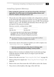
... module(s) from its edges to prevent staticelectricity damage. 4 Remove the side cover (see "Removing the Side Panel" on page 26). 5 Remove the power supply (see "Removing a Slot Cover" on the system configuration you purchased. ✍ Use only PC2100 memory. The minimum memory size is 1 GB. ...necessary, remove the memory module you wish to replace (see "Removing the Power Supply" on page 48). 6 Remove the screw that secures the AGP add-in card to the chassis. 7 Press down the computer, and unplug the power cord. 1 Choose the size of the chassis to discharge static electricity in...
... module(s) from its edges to prevent staticelectricity damage. 4 Remove the side cover (see "Removing the Side Panel" on page 26). 5 Remove the power supply (see "Removing a Slot Cover" on the system configuration you purchased. ✍ Use only PC2100 memory. The minimum memory size is 1 GB. ...necessary, remove the memory module you wish to replace (see "Removing the Power Supply" on page 48). 6 Remove the screw that secures the AGP add-in card to the chassis. 7 Press down the computer, and unplug the power cord. 1 Choose the size of the chassis to discharge static electricity in...
System Reference Manual
Page 50
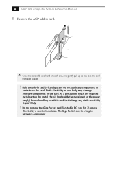
As a precaution, touch any exposed metal part on the metal chassis (preferably the metal part on the power supply) before handling an add-in card to side. ! Static electricity in card. ✍ Grasp the card with one hand on the card. Hold the add-... from side to discharge any components or contacts on the card. Do not remove the Giga Pocket card (located in card by a service technician. 38 VAIO MX Computer System Reference Manual 8 Remove the AGP add-in your body. ! The Giga Pocket card is a fragile hardware component.
As a precaution, touch any exposed metal part on the metal chassis (preferably the metal part on the power supply) before handling an add-in card to side. ! Static electricity in card. ✍ Grasp the card with one hand on the card. Hold the add-... from side to discharge any components or contacts on the card. Do not remove the Giga Pocket card (located in card by a service technician. 38 VAIO MX Computer System Reference Manual 8 Remove the AGP add-in your body. ! The Giga Pocket card is a fragile hardware component.

System Reference Manual
Page 52
40 VAIO MX Computer System Reference Manual 12 Replace the AGP card and secure using the screw removed earlier. ✍ Press down firmly on the AGP card, until the latch locks it into place in the slot. 13 Replace the power supply (see "Replacing the Power Supply" on page 49). 14 Replace the side cover (see "Replacing the Side Panel" on page 27). 15 Reconnect the power cord and turn on the computer. Your computer automatically recognizes the extra memory and configures itself accordingly when you turn on the computer. No further action is required.
40 VAIO MX Computer System Reference Manual 12 Replace the AGP card and secure using the screw removed earlier. ✍ Press down firmly on the AGP card, until the latch locks it into place in the slot. 13 Replace the power supply (see "Replacing the Power Supply" on page 49). 14 Replace the side cover (see "Replacing the Side Panel" on page 27). 15 Reconnect the power cord and turn on the computer. Your computer automatically recognizes the extra memory and configures itself accordingly when you turn on the computer. No further action is required.
System Reference Manual
Page 56
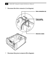
44 VAIO MX Computer System Reference Manual 3 Disconnect the drive connector (A in diagram). Drive connectors (A) Power supply connectors (B) Disk drive holder 4 Disconnect the power connector (B in diagram).
44 VAIO MX Computer System Reference Manual 3 Disconnect the drive connector (A in diagram). Drive connectors (A) Power supply connectors (B) Disk drive holder 4 Disconnect the power connector (B in diagram).
System Reference Manual
Page 58
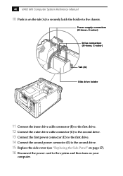
Power supply connectors (D-inner, E-outer) Drive connectors (B-inner, C-outer) Tab (A) Disk drive holder 11 Connect the inner drive cable connector (B) to the first drive. 12 Connect the outer drive cable connector (C) to the second drive. 13 Connect the first power connector (D) to the first drive. 14 Connect the second power... connector (E) to the second drive. 15 Replace the side cover (see "Replacing the Side Panel" on your computer. 46 VAIO MX Computer System Reference Manual 10 Push in on...
Power supply connectors (D-inner, E-outer) Drive connectors (B-inner, C-outer) Tab (A) Disk drive holder 11 Connect the inner drive cable connector (B) to the first drive. 12 Connect the outer drive cable connector (C) to the second drive. 13 Connect the first power connector (D) to the first drive. 14 Connect the second power... connector (E) to the second drive. 15 Replace the side cover (see "Replacing the Side Panel" on your computer. 46 VAIO MX Computer System Reference Manual 10 Push in on...
System Reference Manual
Page 60
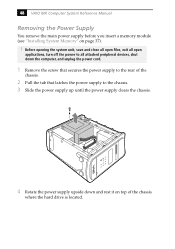
48 VAIO MX Computer System Reference Manual Removing the Power Supply You remove the main power supply before you insert a memory module (see "Installing System Memory" on top of the chassis. 2 Pull the tab that latches the power supply to the rear of the chassis where the hard drive is located. Before opening the system unit, save and close...
48 VAIO MX Computer System Reference Manual Removing the Power Supply You remove the main power supply before you insert a memory module (see "Installing System Memory" on top of the chassis. 2 Pull the tab that latches the power supply to the rear of the chassis where the hard drive is located. Before opening the system unit, save and close...

System Reference Manual
Page 61
Removing, Installing, and Replacing Components 49 Replacing the Power Supply 1 Rotate the power supply down and slide it down along the rails on each side of the chassis opening. 2 Replace the screw that secures the power supply to the rear of the chassis.
Removing, Installing, and Replacing Components 49 Replacing the Power Supply 1 Rotate the power supply down and slide it down along the rails on each side of the chassis opening. 2 Replace the screw that secures the power supply to the rear of the chassis.
System Reference Manual
Page 63
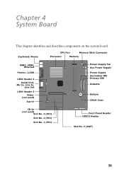
Chapter 4 System Board This chapter identifies and describes components on the system board. Keyboard, Mouse CPU Fan Memory Stick Connector Processor Memory USB3, USB4, Ethernet Printer, i.LINK 1394 Header 2 Serial Port, Mic In, Line In, Line Out 1394 Header 3 Video (not used) Aux-in Power Supply Fan Aux Power Supply Power Supply Secondary IDE Primary IDE Diskette Battery CMOS Clear CD-In (not used) Slot No. 3 (PCI) Slot No. 2 (PCI) Slot No. 1 (PCI) Front Panel Header USB23 Header Slot No. 4 (AGP) 51
Chapter 4 System Board This chapter identifies and describes components on the system board. Keyboard, Mouse CPU Fan Memory Stick Connector Processor Memory USB3, USB4, Ethernet Printer, i.LINK 1394 Header 2 Serial Port, Mic In, Line In, Line Out 1394 Header 3 Video (not used) Aux-in Power Supply Fan Aux Power Supply Power Supply Secondary IDE Primary IDE Diskette Battery CMOS Clear CD-In (not used) Slot No. 3 (PCI) Slot No. 2 (PCI) Slot No. 1 (PCI) Front Panel Header USB23 Header Slot No. 4 (AGP) 51
System Reference Manual
Page 65
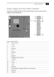
System Board 53 Power Supply and Aux Power Headers The power supply header on the system board connects to the power supply header labelled P1 . 2 4 1 3 10 20 1 11 Power Supply header Pin Signal Name 1 +3.3 V 2 +3.3 V 3 Ground 4 +5 V 5 Ground 6 +5 V 7 Ground 8 PWRGD (Power Good) 9 +5 VSB 10 +12 V 11 +3.3 V 12 -12 V 13 Ground 14 PS-ON# (power supply remote on/off control) 15 Ground 16 Ground
System Board 53 Power Supply and Aux Power Headers The power supply header on the system board connects to the power supply header labelled P1 . 2 4 1 3 10 20 1 11 Power Supply header Pin Signal Name 1 +3.3 V 2 +3.3 V 3 Ground 4 +5 V 5 Ground 6 +5 V 7 Ground 8 PWRGD (Power Good) 9 +5 VSB 10 +12 V 11 +3.3 V 12 -12 V 13 Ground 14 PS-ON# (power supply remote on/off control) 15 Ground 16 Ground
System Reference Manual
Page 66
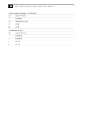
54 VAIO MX Computer System Reference Manual Power Supply header (Continued) Pin Signal Name 17 Ground 18 No Connection 19 +5 V 20 +5 V Aux Power header Pin Signal Name 1 Ground 2 Ground 3 +12 V 4 +12 V
54 VAIO MX Computer System Reference Manual Power Supply header (Continued) Pin Signal Name 17 Ground 18 No Connection 19 +5 V 20 +5 V Aux Power header Pin Signal Name 1 Ground 2 Ground 3 +12 V 4 +12 V


