Reference Manual
Page 2
...information. SONY ELECTRONICS INC. Sony Electronics Inc. Subscriptions to the terms and conditions of a separate user license agreement. Sony, VAIO, the VAIO logo, VAIO Smart, VAIO Digital Studio, VAIO Slimtop, Media Park, DVgate, Media Bar, Handycam, Mavica, PictureGear, i.LINK, and Memory Stick ...copyright protection technology must be identical to the model and serial number when you call your VAIO® computer. The software described herein is prohibited. ii Notice to any machinereadable form without prior ... outside the United States. Model Number: PCV-L640 Serial Number
...information. SONY ELECTRONICS INC. Sony Electronics Inc. Subscriptions to the terms and conditions of a separate user license agreement. Sony, VAIO, the VAIO logo, VAIO Smart, VAIO Digital Studio, VAIO Slimtop, Media Park, DVgate, Media Bar, Handycam, Mavica, PictureGear, i.LINK, and Memory Stick ...copyright protection technology must be identical to the model and serial number when you call your VAIO® computer. The software described herein is prohibited. ii Notice to any machinereadable form without prior ... outside the United States. Model Number: PCV-L640 Serial Number
Reference Manual
Page 12
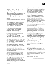
...29 Setting the CMOS Jumper 30 Replacing the Lithium Battery 31 Installing System Memory 34 Removing a Memory Module 36 Replacing the Hard Drive 41 Removing a Slot Cover 44 Covering an Open I/O Slot 45 Chapter 4 - xii VAIO Slimtop™ Reference Manual Chapter 3 - System Board Connectors 48 Front Panel ... LCD Connector 59 Wake On LAN (WOL_CON) Connector 60 LINE IN and LINE OUT Connectors 61 PHONE and MIC Connectors 62 Sony Memory Stick Slot Connector 63 i.LINK Interface Header Connectors 64 i.LINK Connectors 65 Auxiliary Audio In Connector 66 Configuration Jumper and Switches...
...29 Setting the CMOS Jumper 30 Replacing the Lithium Battery 31 Installing System Memory 34 Removing a Memory Module 36 Replacing the Hard Drive 41 Removing a Slot Cover 44 Covering an Open I/O Slot 45 Chapter 4 - xii VAIO Slimtop™ Reference Manual Chapter 3 - System Board Connectors 48 Front Panel ... LCD Connector 59 Wake On LAN (WOL_CON) Connector 60 LINE IN and LINE OUT Connectors 61 PHONE and MIC Connectors 62 Sony Memory Stick Slot Connector 63 i.LINK Interface Header Connectors 64 i.LINK Connectors 65 Auxiliary Audio In Connector 66 Configuration Jumper and Switches...
Reference Manual
Page 13
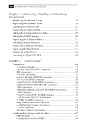
... IDE HDD AUTO DETECTION Screen 86 SAVE & EXIT SETUP Screen 86 EXIT WITHOUT SAVING Screen 86 Chapter 8 - Specifications Processor 97 Chipset 97 PCI Bus 97 Memory Modules (DIMMs 97 DIMM Configurations 98 L2 Cache 98 Graphics 98 Contents xiii Chapter 5 - Ethernet Card Chapter 7 - Miscellaneous Technical Information About User and Supervisor Passwords... 88 Beep Code Error Messages 89 PCI Configuration Status and Error Messages 90 DMA Channel Assignments 91 IRQ Assignments 92 System I/O Address Map 93 Memory Map 95 Chapter 9 - Fax/Modem Card Chapter 6 -
... IDE HDD AUTO DETECTION Screen 86 SAVE & EXIT SETUP Screen 86 EXIT WITHOUT SAVING Screen 86 Chapter 8 - Specifications Processor 97 Chipset 97 PCI Bus 97 Memory Modules (DIMMs 97 DIMM Configurations 98 L2 Cache 98 Graphics 98 Contents xiii Chapter 5 - Ethernet Card Chapter 7 - Miscellaneous Technical Information About User and Supervisor Passwords... 88 Beep Code Error Messages 89 PCI Configuration Status and Error Messages 90 DMA Channel Assignments 91 IRQ Assignments 92 System I/O Address Map 93 Memory Map 95 Chapter 9 - Fax/Modem Card Chapter 6 -
Reference Manual
Page 21
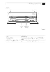
Accommodates Memory Stick media. Slots Identifying Components 7 FD DISC HD PC Card Slot Memory Stick Media Slot SHA0006.VSD Slot PC Card Slot Memory Stick® Media Slot Description Accommodates one Type I or Type II PCMCIA card.
Accommodates Memory Stick media. Slots Identifying Components 7 FD DISC HD PC Card Slot Memory Stick Media Slot SHA0006.VSD Slot PC Card Slot Memory Stick® Media Slot Description Accommodates one Type I or Type II PCMCIA card.
Reference Manual
Page 45
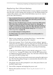
... are different from the Start menu, and then selecting Restart the computer. 2 If the error message "Error: Check date and time settings" appears during the reboot sequence, press F3, then press F2 during the reboot process to power the CMOS memory. ! Sony recommends that you can hold the charge for a short time while...
... are different from the Start menu, and then selecting Restart the computer. 2 If the error message "Error: Check date and time settings" appears during the reboot sequence, press F3, then press F2 during the reboot process to power the CMOS memory. ! Sony recommends that you can hold the charge for a short time while...
Reference Manual
Page 48
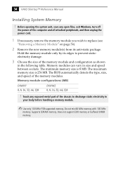
...3 Choose the size of the memory modules. Do not mix 66 MHz memory with 100 MHz memory. Does not support EDO memory or buffered DIMM memory. The maximum memory size is 8 MB. Touch any open files, exit Windows, turn off the power of the computer and all attached peripherals, and...memory module. ✍ Use only 100 MHz FSB-supported memory. The BIOS automatically detects the type, size, and speed of the memory module and configuration as shown in the following table. The minimum memory size is 256 MB. Hold the memory module only by its anti-static package. 34 VAIO Slimtop...
...3 Choose the size of the memory modules. Do not mix 66 MHz memory with 100 MHz memory. Does not support EDO memory or buffered DIMM memory. The maximum memory size is 8 MB. Touch any open files, exit Windows, turn off the power of the computer and all attached peripherals, and...memory module. ✍ Use only 100 MHz FSB-supported memory. The BIOS automatically detects the type, size, and speed of the memory module and configuration as shown in the following table. The minimum memory size is 256 MB. Hold the memory module only by its anti-static package. 34 VAIO Slimtop...
Reference Manual
Page 49
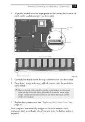
... 35 4 Align the module over the appropriate socket, noting the location of pin 1 on the module and pin 1 on . Your computer automatically recognizes the extra memory and configures itself accordingly when you turn it on the socket. No further action is fully seated, the handles on each side are... not totally straight upright, continue to press down here Handles Memory module (DIMM) 1 Indicates pin 1 OM04586.VSD 5 Carefully but firmly insert the edge of the module into place. 7 Replace the system cover (...
... 35 4 Align the module over the appropriate socket, noting the location of pin 1 on the module and pin 1 on . Your computer automatically recognizes the extra memory and configures itself accordingly when you turn it on the socket. No further action is fully seated, the handles on each side are... not totally straight upright, continue to press down here Handles Memory module (DIMM) 1 Indicates pin 1 OM04586.VSD 5 Carefully but firmly insert the edge of the module into place. 7 Replace the system cover (...
Reference Manual
Page 50
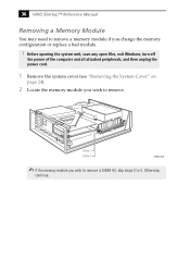
DIMM 1 DIMM 2 KY0073.VSD ✍ If the memory module you wish to remove. Otherwise, continue. Before opening the system unit, save any open files, exit Windows, turn off the power of the computer and all attached peripherals, and then unplug the power cord. 1 Remove the system cover (see "Removing the System Cover" on page 24). 2 Locate the memory module you wish to remove is DIMM #2, skip steps 3 to remove a memory module if you change the memory configuration or replace a bad module. ! 36 VAIO Slimtop™ Reference Manual Removing a Memory Module You may need to 5.
DIMM 1 DIMM 2 KY0073.VSD ✍ If the memory module you wish to remove. Otherwise, continue. Before opening the system unit, save any open files, exit Windows, turn off the power of the computer and all attached peripherals, and then unplug the power cord. 1 Remove the system cover (see "Removing the System Cover" on page 24). 2 Locate the memory module you wish to remove is DIMM #2, skip steps 3 to remove a memory module if you change the memory configuration or replace a bad module. ! 36 VAIO Slimtop™ Reference Manual Removing a Memory Module You may need to 5.
Reference Manual
Page 52
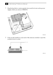
Push out Handles KY0042.VSD MAN003.VSD 6 Push out the handle on the power supply while you remove DIMM #1. 38 VAIO Slimtop™ Reference Manual 5 Flip the hard drive carrier upside down and let it rest on each side of the memory module to eject the module from its socket.
Push out Handles KY0042.VSD MAN003.VSD 6 Push out the handle on the power supply while you remove DIMM #1. 38 VAIO Slimtop™ Reference Manual 5 Flip the hard drive carrier upside down and let it rest on each side of the memory module to eject the module from its socket.
Reference Manual
Page 53
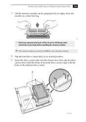
Removing, Installing, and Replacing Components 39 7 Lift the memory module out by grasping it by its normal position. 9 Insert the drive carrier tabs into the chassis slots, then slip the drive carrier down until ... carrier. MAN002B.VSD Touch any exposed metal part of the chassis to its edges. Store the module in your body before handling the memory module. ✍ If the memory module you removed is DIMM #2, stop. KY ! Otherwise, continue. 8 Flip the hard drive carrier back to discharge static electricity in a static-free bag...
Removing, Installing, and Replacing Components 39 7 Lift the memory module out by grasping it by its normal position. 9 Insert the drive carrier tabs into the chassis slots, then slip the drive carrier down until ... carrier. MAN002B.VSD Touch any exposed metal part of the chassis to its edges. Store the module in your body before handling the memory module. ✍ If the memory module you removed is DIMM #2, stop. KY ! Otherwise, continue. 8 Flip the hard drive carrier back to discharge static electricity in a static-free bag...
Reference Manual
Page 61
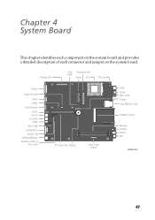
Primary IDE CTRL Secondary IDE PWR Power CPU CPU Fan Printer Wake On LAN Serial CMOS VGA Monitor USB1 Line In Line Out i.LINK IEEE-1394 LCD Monitor Config. SW Keyboard/Mouse Auxiliary Audio In (not used) O1 2 3 4 5 6 N PCI Riser Slot Battery Front Panel header USB2 i.LINK IEEE-1394 Floppy Sony Memory Stick PCMCIA Socket Memory Volume Phone Mic OM04581.VSD 47 Chapter 4 System Board This chapter identifies each component on the system board and provides a detailed description of each connector and jumper on the system board.
Primary IDE CTRL Secondary IDE PWR Power CPU CPU Fan Printer Wake On LAN Serial CMOS VGA Monitor USB1 Line In Line Out i.LINK IEEE-1394 LCD Monitor Config. SW Keyboard/Mouse Auxiliary Audio In (not used) O1 2 3 4 5 6 N PCI Riser Slot Battery Front Panel header USB2 i.LINK IEEE-1394 Floppy Sony Memory Stick PCMCIA Socket Memory Volume Phone Mic OM04581.VSD 47 Chapter 4 System Board This chapter identifies each component on the system board and provides a detailed description of each connector and jumper on the system board.
Reference Manual
Page 66
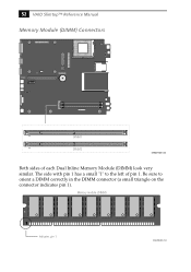
52 VAIO Slimtop™ Reference Manual Memory Module (DIMM) Connectors O1 2 3 4 5 6 N DIMM1 DIMM2 OM04710A.VSD Both sides of pin 1. Memory module (DIMM) 1 Indicates pin 1 OM04908B.VSD Be sure to the left of each Dual Inline Memory Module (DIMM) look very similar. The side with pin 1 has a small "1" to orient a DIMM correctly in the DIMM connector (a small triangle on the connector indicates pin 1).
52 VAIO Slimtop™ Reference Manual Memory Module (DIMM) Connectors O1 2 3 4 5 6 N DIMM1 DIMM2 OM04710A.VSD Both sides of pin 1. Memory module (DIMM) 1 Indicates pin 1 OM04908B.VSD Be sure to the left of each Dual Inline Memory Module (DIMM) look very similar. The side with pin 1 has a small "1" to orient a DIMM correctly in the DIMM connector (a small triangle on the connector indicates pin 1).
Reference Manual
Page 77
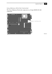
System Board 63 Sony Memory Stick Slot Connector The Sony Memory Stick slot connector is a 10-pin MCR 103-10S connector. O1 2 3 4 5 6 N Sony Memory Stick KY0097.VSD
System Board 63 Sony Memory Stick Slot Connector The Sony Memory Stick slot connector is a 10-pin MCR 103-10S connector. O1 2 3 4 5 6 N Sony Memory Stick KY0097.VSD
Reference Manual
Page 94
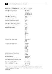
80 VAIO Slimtop™ Reference Manual CHIPSET FEATURES SETUP Screen SDRAM Configuration [By SPD] Disabled 7ns (143MHz) 8ns (125MHz) SDRAM CAS Latency* [2T] 3T SDRAM RAS to CAS ... 12T 16T 32T Infinite 0T 2T 4T SDRAM MA Wait State [Normal] Slow Fast Graphics Aperture Size [64MB] 128MB 256MB 4MB 8MB 16MB 32MB Video Memory Cache Mode [UC] USWC PCI 2.1 Support [Enabled] Disabled DRAM are 64 (Not 72) bits wide Data Integrity Mode† Non-ECC Onboard FDC Controller [Enabled...
80 VAIO Slimtop™ Reference Manual CHIPSET FEATURES SETUP Screen SDRAM Configuration [By SPD] Disabled 7ns (143MHz) 8ns (125MHz) SDRAM CAS Latency* [2T] 3T SDRAM RAS to CAS ... 12T 16T 32T Infinite 0T 2T 4T SDRAM MA Wait State [Normal] Slow Fast Graphics Aperture Size [64MB] 128MB 256MB 4MB 8MB 16MB 32MB Video Memory Cache Mode [UC] USWC PCI 2.1 Support [Enabled] Disabled DRAM are 64 (Not 72) bits wide Data Integrity Mode† Non-ECC Onboard FDC Controller [Enabled...
Reference Manual
Page 101
Chapter 8 Miscellaneous Technical Information This chapter contains information on the following subjects: ❑ User and Supervisor password ❑ Beep code error messages ❑ PCI configuration status and error messages ❑ DMA channel assignments ❑ IRQ assignments ❑ System I/O address map ❑ Memory map 87
Chapter 8 Miscellaneous Technical Information This chapter contains information on the following subjects: ❑ User and Supervisor password ❑ Beep code error messages ❑ PCI configuration status and error messages ❑ DMA channel assignments ❑ IRQ assignments ❑ System I/O address map ❑ Memory map 87
Reference Manual
Page 104
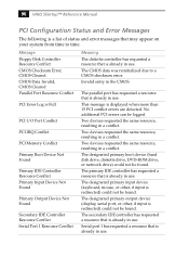
...CMOS Data Invalid, CMOS Cleared Parallel Port Resource Conflict PCI Error Log is Full PCI I/O Port Conflict PCI IRQ Conflict PCI Memory Conflict Primary Boot Device Not Found Primary IDE Controller Resource Conflict Primary Input Device Not Found Primary Output Device Not Found Secondary ...in use . The designated primary input device (keyboard, mouse, or other , if input is redirected) could not be logged. 90 VAIO Slimtop™ Reference Manual PCI Configuration Status and Error Messages The following is displayed when more than 15 PCI conflict errors are detected. No ...
...CMOS Data Invalid, CMOS Cleared Parallel Port Resource Conflict PCI Error Log is Full PCI I/O Port Conflict PCI IRQ Conflict PCI Memory Conflict Primary Boot Device Not Found Primary IDE Controller Resource Conflict Primary Input Device Not Found Primary Output Device Not Found Secondary ...in use . The designated primary input device (keyboard, mouse, or other , if input is redirected) could not be logged. 90 VAIO Slimtop™ Reference Manual PCI Configuration Status and Error Messages The following is displayed when more than 15 PCI conflict errors are detected. No ...
Reference Manual
Page 105
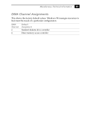
DMA Channel 2 4 Default Assignment Standard diskette drive controller Direct memory access controller Miscellaneous Technical Information 91 DMA Channel Assignments This shows the factory default values. Windows 98 reassigns resources to best meet the needs of a particular configuration.
DMA Channel 2 4 Default Assignment Standard diskette drive controller Direct memory access controller Miscellaneous Technical Information 91 DMA Channel Assignments This shows the factory default values. Windows 98 reassigns resources to best meet the needs of a particular configuration.
Reference Manual
Page 106
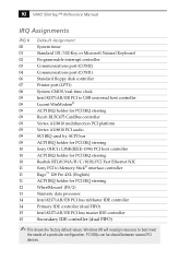
... to Memory Stick® interface controller Rage™ 128 Pro 4XL (English) ACPI IRQ holder for PCI IRQ steering Realtek RTL8139(A/B/C/8130) PCI Fast Ethernet NIC Sony PCI to best meet the needs of a particular configuration. PCI IRQs can be shared between several PCI devices. 92 VAIO Slimtop™...CardBus controller Vortex AU8810 multifunction PCI platform Vortex AU8810 PCI audio SCI IRQ used by ACPI bus ACPI IRQ holder for PCI IRQ steering Sony OHCI i.LINK(IEEE-1394) PCI host controller ACPI IRQ holder for PCI IRQ steering WheelMouse1 (PS/2) Numeric data processor Intel 82371AB/...
... to Memory Stick® interface controller Rage™ 128 Pro 4XL (English) ACPI IRQ holder for PCI IRQ steering Realtek RTL8139(A/B/C/8130) PCI Fast Ethernet NIC Sony PCI to best meet the needs of a particular configuration. PCI IRQs can be shared between several PCI devices. 92 VAIO Slimtop™...CardBus controller Vortex AU8810 multifunction PCI platform Vortex AU8810 PCI audio SCI IRQ used by ACPI bus ACPI IRQ holder for PCI IRQ steering Sony OHCI i.LINK(IEEE-1394) PCI host controller ACPI IRQ holder for PCI IRQ steering WheelMouse1 (PS/2) Numeric data processor Intel 82371AB/...
Reference Manual
Page 111
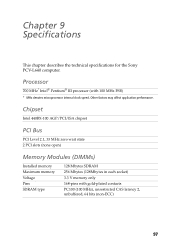
... Level 2.1, 33 MHz zero wait state 2 PCI slots (none open) Memory Modules (DIMMs) Installed memory Maximum memory Voltage Pins SDRAM type 128 Mbytes SDRAM 256 Mbytes (128Mbytes in each socket) 3.3 V memory only 168-pins with 100 MHz FSB) * MHz denotes microprocessor internal clock speed. Chapter 9 Specifications This chapter describes the technical specifications for the Sony PCV-L640 computer.
... Level 2.1, 33 MHz zero wait state 2 PCI slots (none open) Memory Modules (DIMMs) Installed memory Maximum memory Voltage Pins SDRAM type 128 Mbytes SDRAM 256 Mbytes (128Mbytes in each socket) 3.3 V memory only 168-pins with 100 MHz FSB) * MHz denotes microprocessor internal clock speed. Chapter 9 Specifications This chapter describes the technical specifications for the Sony PCV-L640 computer.
Reference Manual
Page 112
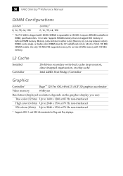
...256 colors (8 bits) Up to 256 MB. Do not mix 66 MHz memory with 128 MB. Computer SDRAM is unbuffered DIMM, specification Rev. 1.0 or later. Supports SDRAM memory. Does not support EDO memory or buffered DIMM memory. DIMMs can vary between sockets. DIMMs must be single- L2 Cache Installed ... for Plug and Play displays. or double-sided. Memory size can be 3.3V unbuffered 4-clock, 64-bit or 72-bit, 100 MHz SDRAM module. 98 VAIO Slimtop™ Reference Manual DIMM Configurations DIMM1* 0, 16, 32, 64, 128 DIMM2* 0, 16, 32, 64, 128 * The PCV-L640 is shipped with 100 MHz...
...256 colors (8 bits) Up to 256 MB. Do not mix 66 MHz memory with 128 MB. Computer SDRAM is unbuffered DIMM, specification Rev. 1.0 or later. Supports SDRAM memory. Does not support EDO memory or buffered DIMM memory. DIMMs can vary between sockets. DIMMs must be single- L2 Cache Installed ... for Plug and Play displays. or double-sided. Memory size can be 3.3V unbuffered 4-clock, 64-bit or 72-bit, 100 MHz SDRAM module. 98 VAIO Slimtop™ Reference Manual DIMM Configurations DIMM1* 0, 16, 32, 64, 128 DIMM2* 0, 16, 32, 64, 128 * The PCV-L640 is shipped with 100 MHz...


