
Reference Manual
Page 2
... VAIO logo, VAIO Smart, VAIO Digital Studio, VAIO Slimtop, Media Park, DVgate, Media Bar, Handycam, Mavica, PictureGear, i.LINK, and Memory Stick are registered trademarks of Sony. Reverse engineering or disassembly is subject to this copyright protection technology must be transported or used outside the United States. This product incorporates copyright protection technology that is prohibited. This manual...
... VAIO logo, VAIO Smart, VAIO Digital Studio, VAIO Slimtop, Media Park, DVgate, Media Bar, Handycam, Mavica, PictureGear, i.LINK, and Memory Stick are registered trademarks of Sony. Reverse engineering or disassembly is subject to this copyright protection technology must be transported or used outside the United States. This product incorporates copyright protection technology that is prohibited. This manual...
Reference Manual
Page 3
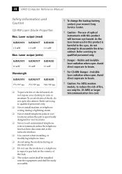
... UJDA310V UJDA310T UJDA320 773-797 nm 773-797 nm 780-795 nm ❑ To prevent fire or shock hazard, do not expose your nearest Sony Service Center. ! Refer servicing to beam. ! Danger - To change the backup battery, contact your desktop to rain or moisture.To avoid electrical... . Laser output (read) UJDA310V UJDA310T UJDA320 1.8 mW 1.8 mW 1.8 mW Max. Caution: For ADSL modem models, to disassemble the drive cabinet. iii VAIO Computer Reference Manual Safety Information and Caution CD-RW Laser Diode Properties Max. Visible and invisible laser radiation when open .
... UJDA310V UJDA310T UJDA320 773-797 nm 773-797 nm 780-795 nm ❑ To prevent fire or shock hazard, do not expose your nearest Sony Service Center. ! Refer servicing to beam. ! Danger - To change the backup battery, contact your desktop to rain or moisture.To avoid electrical... . Laser output (read) UJDA310V UJDA310T UJDA320 1.8 mW 1.8 mW 1.8 mW Max. Caution: For ADSL modem models, to disassemble the drive cabinet. iii VAIO Computer Reference Manual Safety Information and Caution CD-RW Laser Diode Properties Max. Visible and invisible laser radiation when open .
Reference Manual
Page 5
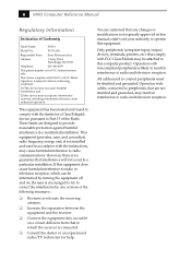
v VAIO Computer Reference Manual Regulatory Information Declaration of the Rules. However, there is likely to result in interference to radio and television reception. Only peripherals (computer input/output devices, terminals, printers, etc.) that comply with cables, connected to peripherals, that are... installed and used to Part 15 of Conformity Trade Name: SONY Model No.: PCV-L640 Responsible Party: Sony Electronics Inc. If this equipment. Operation with FCC Class B limits may result in this manual could void your authority to operate this equipment does cause harmful...
v VAIO Computer Reference Manual Regulatory Information Declaration of the Rules. However, there is likely to result in interference to radio and television reception. Only peripherals (computer input/output devices, terminals, printers, etc.) that comply with cables, connected to peripherals, that are... installed and used to Part 15 of Conformity Trade Name: SONY Model No.: PCV-L640 Responsible Party: Sony Electronics Inc. If this equipment. Operation with FCC Class B limits may result in this manual could void your authority to operate this equipment does cause harmful...
Reference Manual
Page 7
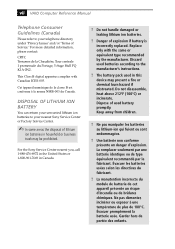
....' Keep away from children. ! This Class B digital apparatus complies with the same or equivalent type recommended by the manufacturer. For the Sony Service Center nearest you, call 1-888-476-6972 in the United States or 1-800-961-7669 in this device may be prohibited. Dispose... batterie de cet appareil présente un risque d'incendie ou de brûlures chimiques. vii VAIO Computer Reference Manual Telephone Consumer Guidelines (Canada) Please refer to your nearest Sony Service Center or Factory Service Center. ✍ In some areas the disposal of lithium ion batteries in...
....' Keep away from children. ! This Class B digital apparatus complies with the same or equivalent type recommended by the manufacturer. For the Sony Service Center nearest you, call 1-888-476-6972 in the United States or 1-800-961-7669 in this device may be prohibited. Dispose... batterie de cet appareil présente un risque d'incendie ou de brûlures chimiques. vii VAIO Computer Reference Manual Telephone Consumer Guidelines (Canada) Please refer to your nearest Sony Service Center or Factory Service Center. ✍ In some areas the disposal of lithium ion batteries in...
Reference Manual
Page 12
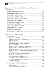
... LAN (WOL_CON) Connector 60 LINE IN and LINE OUT Connectors 61 PHONE and MIC Connectors 62 Sony Memory Stick Slot Connector 63 i.LINK Interface Header Connectors 64 i.LINK Connectors 65 Auxiliary Audio In Connector 66 Configuration Jumper and Switches 67 CMOS Jumper 67 Configuration Switches (SW 68 xii VAIO Slimtop™ Reference Manual Chapter 3 -
... LAN (WOL_CON) Connector 60 LINE IN and LINE OUT Connectors 61 PHONE and MIC Connectors 62 Sony Memory Stick Slot Connector 63 i.LINK Interface Header Connectors 64 i.LINK Connectors 65 Auxiliary Audio In Connector 66 Configuration Jumper and Switches 67 CMOS Jumper 67 Configuration Switches (SW 68 xii VAIO Slimtop™ Reference Manual Chapter 3 -
Reference Manual
Page 15
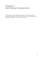
Internal components are identified in Chapters 3, 4, and 5 of the VAIO® Computer. Chapter 1 Identifying Components The following sections identify and describe each component that is visible from the exterior of this manual. 1
Internal components are identified in Chapters 3, 4, and 5 of the VAIO® Computer. Chapter 1 Identifying Components The following sections identify and describe each component that is visible from the exterior of this manual. 1
Reference Manual
Page 18
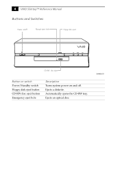
4 VAIO Slimtop™ Reference Manual Buttons and Switches Power on/off Manual eject hole Floppy disk eject FD DISC HD CD-RW disc eject Button or switch Power/Standby switch Floppy disk eject button CD-RW disc eject button Emergency eject hole Description Turns system power on and off. Ejects an optical disc. Automatically opens the CD-RW tray. Ejects a diskette. SHA0003.VSD
4 VAIO Slimtop™ Reference Manual Buttons and Switches Power on/off Manual eject hole Floppy disk eject FD DISC HD CD-RW disc eject Button or switch Power/Standby switch Floppy disk eject button CD-RW disc eject button Emergency eject hole Description Turns system power on and off. Ejects an optical disc. Automatically opens the CD-RW tray. Ejects a diskette. SHA0003.VSD
Reference Manual
Page 20
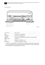
... to the device if the device also has a 6-pin i.LINK connector. A 6-pin i.LINK connector can supply power from the computer to the device. Connects to USB devices. Connects to headphones. 6 VAIO Slimtop™ Reference Manual Connectors FD DISC HD MIC PHONES VOLUME i.LINK USB SHA0005.VSD Connector MIC PHONES i.LINK® (IEEE-1394)* USB...
... to the device if the device also has a 6-pin i.LINK connector. A 6-pin i.LINK connector can supply power from the computer to the device. Connects to USB devices. Connects to headphones. 6 VAIO Slimtop™ Reference Manual Connectors FD DISC HD MIC PHONES VOLUME i.LINK USB SHA0005.VSD Connector MIC PHONES i.LINK® (IEEE-1394)* USB...
Reference Manual
Page 22
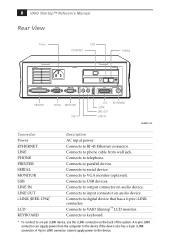
... to output connector on audio device. Connects to the device. A 4-pin i.LINK connector cannot supply power to VAIO Slimtop™ LCD monitor. 8 VAIO Slimtop™ Reference Manual Rear View Power LINE ETHERNET PHONE PRINTER SERIAL MONITOR LINE USB LINE IN OUT I.LINK S400 LCD PHONE KEYBOARD PRINTER...a 6-pin i.LINK device, use the i.LINK connector on audio device. Connects to keyboard. * To connect to phone cable from the computer to RJ-45 Ethernet connector. A 6-pin i.LINK connector can supply power from wall jack. Connects to the device if the device also ...
... to output connector on audio device. Connects to the device. A 4-pin i.LINK connector cannot supply power to VAIO Slimtop™ LCD monitor. 8 VAIO Slimtop™ Reference Manual Rear View Power LINE ETHERNET PHONE PRINTER SERIAL MONITOR LINE USB LINE IN OUT I.LINK S400 LCD PHONE KEYBOARD PRINTER...a 6-pin i.LINK device, use the i.LINK connector on audio device. Connects to keyboard. * To connect to phone cable from the computer to RJ-45 Ethernet connector. A 6-pin i.LINK connector can supply power from wall jack. Connects to the device if the device also ...
Reference Manual
Page 24
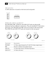
... have different connections. Electret condenser microphone input. 1.0 Vrms input (max), 50 Kohm impedance. 1.0 Vrms out (max). They are located on the front panel. 10 VAIO Slimtop™ Reference Manual USB Connectors A USB connector is located on the rear panel. The PHONES and MIC jacks are standard 3.5 mm stereo mini-jacks. PHONES MIC LINE...
... have different connections. Electret condenser microphone input. 1.0 Vrms input (max), 50 Kohm impedance. 1.0 Vrms out (max). They are located on the front panel. 10 VAIO Slimtop™ Reference Manual USB Connectors A USB connector is located on the rear panel. The PHONES and MIC jacks are standard 3.5 mm stereo mini-jacks. PHONES MIC LINE...
Reference Manual
Page 26
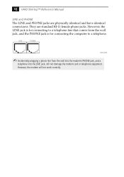
12 VAIO Slimtop™ Reference Manual LINE and PHONE The LINE and PHONE jacks are standard RJ-11 female phone jacks. They are physically identical and have identical connections. However, the ... for connecting to a telephone. LINE PHONE KY0014.VSD ✍ Accidentally plugging a phone line from the wall jack, and the PHONE jack is for connecting the computer to a telephone line that comes from the wall into the modem's PHONE jack, and a telephone into the LINE jack, will not work correctly. However, the...
12 VAIO Slimtop™ Reference Manual LINE and PHONE The LINE and PHONE jacks are standard RJ-11 female phone jacks. They are physically identical and have identical connections. However, the ... for connecting to a telephone. LINE PHONE KY0014.VSD ✍ Accidentally plugging a phone line from the wall jack, and the PHONE jack is for connecting the computer to a telephone line that comes from the wall into the modem's PHONE jack, and a telephone into the LINE jack, will not work correctly. However, the...
Reference Manual
Page 28
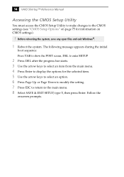
..., type Y, then press Enter. Follow the onscreen prompts. Before rebooting the system, save any open files and exit Windows®. 1 Reboot the system. 14 VAIO Slimtop™ Reference Manual Accessing the CMOS Setup Utility You must access the CMOS Setup Utility to make changes to the CMOS settings (see "CMOS Setup Options" on...
..., type Y, then press Enter. Follow the onscreen prompts. Before rebooting the system, save any open files and exit Windows®. 1 Reboot the system. 14 VAIO Slimtop™ Reference Manual Accessing the CMOS Setup Utility You must access the CMOS Setup Utility to make changes to the CMOS settings (see "CMOS Setup Options" on...
Reference Manual
Page 30
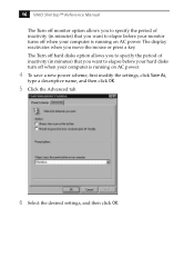
... minutes) that you want to elapse before your hard disks turn off when your computer is running on AC power. The display reactivates when you move the mouse or press a key. 16 VAIO Slimtop™ Reference Manual The Turn off monitor option allows you to specify the period of inactivity (in ...minutes) that you want to elapse before your monitor turns off when your computer is running on AC power. 4 To save a new...
... minutes) that you want to elapse before your hard disks turn off when your computer is running on AC power. The display reactivates when you move the mouse or press a key. 16 VAIO Slimtop™ Reference Manual The Turn off monitor option allows you to specify the period of inactivity (in ...minutes) that you want to elapse before your monitor turns off when your computer is running on AC power. 4 To save a new...
Reference Manual
Page 32
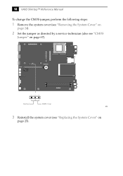
O1 2 3 4 5 6 N 123 Normal CMOS Clear KY0 3 Reinstall the system cover (see "CMOS Jumper" on page 25). 18 VAIO Slimtop™ Reference Manual To change the CMOS jumper, perform the following steps: 1 Remove the system cover (see "Removing the System Cover" on page 24). 2 Set the jumper as directed by a service technician (also see "Replacing the System Cover" on page 67).
O1 2 3 4 5 6 N 123 Normal CMOS Clear KY0 3 Reinstall the system cover (see "CMOS Jumper" on page 25). 18 VAIO Slimtop™ Reference Manual To change the CMOS jumper, perform the following steps: 1 Remove the system cover (see "Removing the System Cover" on page 24). 2 Set the jumper as directed by a service technician (also see "Replacing the System Cover" on page 67).
Reference Manual
Page 34
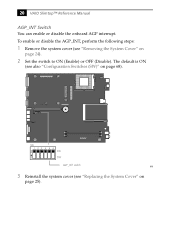
To enable or disable the AGP_INT, perform the following steps: 1 Remove the system cover (see "Removing the System Cover" on page 68). The default is ON (see "Replacing the System Cover" on page 25). 20 VAIO Slimtop™ Reference Manual AGP_INT Switch You can enable or disable the onboard AGP interrupt. O1 2 3 4 5 6 N SW 123456 O N ON OFF AGP_INT switch KY0 3 Reinstall the system cover (see also "Configuration Switches (SW)" on page 24). 2 Set the switch to ON (Enable) or OFF (Disable).
To enable or disable the AGP_INT, perform the following steps: 1 Remove the system cover (see "Removing the System Cover" on page 68). The default is ON (see "Replacing the System Cover" on page 25). 20 VAIO Slimtop™ Reference Manual AGP_INT Switch You can enable or disable the onboard AGP interrupt. O1 2 3 4 5 6 N SW 123456 O N ON OFF AGP_INT switch KY0 3 Reinstall the system cover (see also "Configuration Switches (SW)" on page 24). 2 Set the switch to ON (Enable) or OFF (Disable).
Reference Manual
Page 38
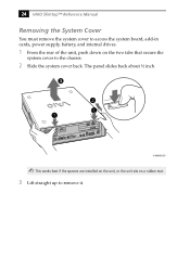
The panel slides back about ½ inch. 3 KY0064B.VSD ✍ This works best if the spacers are installed on the unit, or the unit sits on the two tabs that secure the system cover to remove it. 24 VAIO Slimtop™ Reference Manual Removing the System Cover You must remove the system cover to access the system board, add-in cards, power supply, battery, and internal drives. 1 From the rear of the unit, push down on a rubber mat. 3 Lift straight up to the chassis. 2 Slide the system cover back.
The panel slides back about ½ inch. 3 KY0064B.VSD ✍ This works best if the spacers are installed on the unit, or the unit sits on the two tabs that secure the system cover to remove it. 24 VAIO Slimtop™ Reference Manual Removing the System Cover You must remove the system cover to access the system board, add-in cards, power supply, battery, and internal drives. 1 From the rear of the unit, push down on a rubber mat. 3 Lift straight up to the chassis. 2 Slide the system cover back.
Reference Manual
Page 40
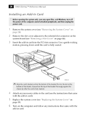
... inserted. 4 Attach any instructions that came with the add-in card into the slot at the bottom of the computer and all attached peripherals, and then unplug the power cord. 1 Remove the system cover (see "Removing the System... that came with the add-in card). 5 Replace the system cover (see "Removing a Slot Cover" on the computer and follow any necessary cables to the selected slot connector on the system board (see "Replacing the System Cover" on...that the top of the bracket fits into the PCI slot connector. 26 VAIO Slimtop™ Reference Manual Installing an Add-In Card !
... inserted. 4 Attach any instructions that came with the add-in card into the slot at the bottom of the computer and all attached peripherals, and then unplug the power cord. 1 Remove the system cover (see "Removing the System... that came with the add-in card). 5 Replace the system cover (see "Removing a Slot Cover" on the computer and follow any necessary cables to the selected slot connector on the system board (see "Replacing the System Cover" on...that the top of the bracket fits into the PCI slot connector. 26 VAIO Slimtop™ Reference Manual Installing an Add-In Card !
Reference Manual
Page 42
28 VAIO Slimtop™ Reference Manual 5 If you do not replace the card or install another add-in card, install a slot cover over the vacant slot at the rear of the chassis (see "Covering an Open I/O Slot" on page 45). 6 Replace the system cover (see "Replacing the System Cover" on page 25).
28 VAIO Slimtop™ Reference Manual 5 If you do not replace the card or install another add-in card, install a slot cover over the vacant slot at the rear of the chassis (see "Covering an Open I/O Slot" on page 45). 6 Replace the system cover (see "Replacing the System Cover" on page 25).
Reference Manual
Page 44
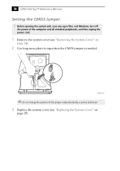
30 VAIO Slimtop™ Reference Manual Setting the CMOS Jumper ! Before opening the system unit, save any open files, exit Windows, turn off the power of this jumper unless directed by a service technician. 3 Replace the system cover (see "Removing the System Cover" on page 25). MAN007.VSD ✍ Do not change the position of the computer and all attached peripherals, and then unplug the power cord. 1 Remove the system cover (see "Replacing the System Cover" on page 24). 2 Use long-nose pliers to reposition the CMOS jumper as needed.
30 VAIO Slimtop™ Reference Manual Setting the CMOS Jumper ! Before opening the system unit, save any open files, exit Windows, turn off the power of this jumper unless directed by a service technician. 3 Replace the system cover (see "Removing the System Cover" on page 25). MAN007.VSD ✍ Do not change the position of the computer and all attached peripherals, and then unplug the power cord. 1 Remove the system cover (see "Replacing the System Cover" on page 24). 2 Use long-nose pliers to reposition the CMOS jumper as needed.
Reference Manual
Page 46
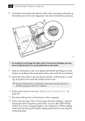
... "Error: Check date and time settings." If it becomes dislodged, you can skip the remaining steps. If no error message displays, the computer's CMOS settings were retained during the reboot sequence, press DEL to dislodge the ribbon cable. One side of fire or explosion. 11 Replace...you may present a risk of the battery pops up , and press down until the battery feels secure. ✍ The Sony CR2032 battery is recommended. KY00 ! 32 VAIO Slimtop™ Reference Manual 8 Carefully reach under the ribbon cable with the plus (+) side up . Be carefull not to access the CMOS Setup ...
... "Error: Check date and time settings." If it becomes dislodged, you can skip the remaining steps. If no error message displays, the computer's CMOS settings were retained during the reboot sequence, press DEL to dislodge the ribbon cable. One side of fire or explosion. 11 Replace...you may present a risk of the battery pops up , and press down until the battery feels secure. ✍ The Sony CR2032 battery is recommended. KY00 ! 32 VAIO Slimtop™ Reference Manual 8 Carefully reach under the ribbon cable with the plus (+) side up . Be carefull not to access the CMOS Setup ...


