Reference Manual
Page 2
...may not necessarily be transported or used outside the United States. SONY ELECTRONICS INC. Sony, VAIO, the VAIO logo, and i.LINK are trademarks of this product. Use of Intel Corporation. Notice to the model and serial number when you call your VAIO® computer. Reproduction in whole or in part without notice. This manual... with participating financial institutions. This product incorporates copyright protection technology that is prohibited. All other rights owners. Refer to Users © 2000 Sony Electronics Inc. Model Number: PCV-J100 Serial Number ii
...may not necessarily be transported or used outside the United States. SONY ELECTRONICS INC. Sony, VAIO, the VAIO logo, and i.LINK are trademarks of this product. Use of Intel Corporation. Notice to the model and serial number when you call your VAIO® computer. Reproduction in whole or in part without notice. This manual... with participating financial institutions. This product incorporates copyright protection technology that is prohibited. All other rights owners. Refer to Users © 2000 Sony Electronics Inc. Model Number: PCV-J100 Serial Number ii
Reference Manual
Page 12
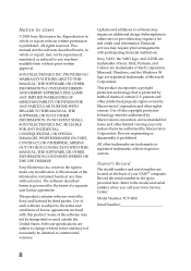
... GAME Connector 57 HEADPHONES, LINE IN, MIC Connectors 58 CD-IN Connector 59 AUX-IN Connector 60 WOL Connector 61 Configuration Jumper 62 Chapter 5 - xii VAIO® Reference Manual Chapter 3 -
... GAME Connector 57 HEADPHONES, LINE IN, MIC Connectors 58 CD-IN Connector 59 AUX-IN Connector 60 WOL Connector 61 Configuration Jumper 62 Chapter 5 - xii VAIO® Reference Manual Chapter 3 -
Reference Manual
Page 15
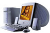
Internal components are identified in the appropriate section of the VAIO® Computer. Chapter 1 Identifying Components The following sections identify and describe each component that is visible from the exterior of this manual. 1
Internal components are identified in the appropriate section of the VAIO® Computer. Chapter 1 Identifying Components The following sections identify and describe each component that is visible from the exterior of this manual. 1
Reference Manual
Page 18
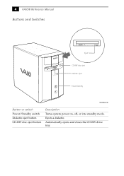
4 VAIO® Reference Manual Buttons and Switches Eject hole CD-RW disc eject Diskette eject Power/Standby FRNTPNLB.VSD Button or switch Power/Standby switch Diskette eject button CD-RW disc eject button Description Turns system power on, off, or into standby mode. Ejects a diskette. Automatically opens and closes the CD-RW drive tray.
4 VAIO® Reference Manual Buttons and Switches Eject hole CD-RW disc eject Diskette eject Power/Standby FRNTPNLB.VSD Button or switch Power/Standby switch Diskette eject button CD-RW disc eject button Description Turns system power on, off, or into standby mode. Ejects a diskette. Automatically opens and closes the CD-RW drive tray.
Reference Manual
Page 22
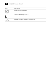
8 VAIO® Reference Manual Icon Description TELEPHONE (for phone) i.LINK® (IEEE1394) interface Ethernet connector (10Base-T/100Base-TX)
8 VAIO® Reference Manual Icon Description TELEPHONE (for phone) i.LINK® (IEEE1394) interface Ethernet connector (10Base-T/100Base-TX)

Reference Manual
Page 24
10 VAIO® Reference Manual PRINTER Connector The PRINTER connector is a standard 25-pin DB-25 female connector. 13 25 14 1 KY0005.VSD MONITOR The MONITOR connector is a standard 15-pin female high-density VGAtype connector. 10 15 5 11 1 6 KY0004.VSD
10 VAIO® Reference Manual PRINTER Connector The PRINTER connector is a standard 25-pin DB-25 female connector. 13 25 14 1 KY0005.VSD MONITOR The MONITOR connector is a standard 15-pin female high-density VGAtype connector. 10 15 5 11 1 6 KY0004.VSD
Reference Manual
Page 26
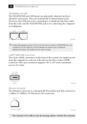
...VAIO® Reference Manual TELEPHONE and LINE The TELEPHONE and LINE jacks are standard RJ-11 female phone jacks. The 6-pin connector supplies 10V to a device if the device also has a 6-pin i.LINK connector. However, the LINE jack is a standard RJ-45 modular jack that comes from the computer...The 6-pin i.LINK connectors on the back of the system can supply power from the wall, and the TELEPHONE jack is for connecting the computer to a 10Base-T/100Base-TX Ethernet LAN connection. LINE PHONE KY0014.VSD ✍ Accidentally plugging a phone line from the wall into the modem...
...VAIO® Reference Manual TELEPHONE and LINE The TELEPHONE and LINE jacks are standard RJ-11 female phone jacks. The 6-pin connector supplies 10V to a device if the device also has a 6-pin i.LINK connector. However, the LINE jack is a standard RJ-45 modular jack that comes from the computer...The 6-pin i.LINK connectors on the back of the system can supply power from the wall, and the TELEPHONE jack is for connecting the computer to a 10Base-T/100Base-TX Ethernet LAN connection. LINE PHONE KY0014.VSD ✍ Accidentally plugging a phone line from the wall into the modem...
Reference Manual
Page 30
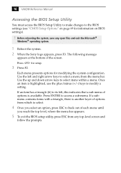
... keys to select a menu from any open files and exit the Microsoft® Windows® operating system. 1 Reboot the system. 2 When the Sony logo appears, press F3. 16 VAIO® Reference Manual Accessing the BIOS Setup Utility You must access the BIOS Setup Utility to make changes to the BIOS settings (see...
... keys to select a menu from any open files and exit the Microsoft® Windows® operating system. 1 Reboot the system. 2 When the Sony logo appears, press F3. 16 VAIO® Reference Manual Accessing the BIOS Setup Utility You must access the BIOS Setup Utility to make changes to the BIOS settings (see...

Reference Manual
Page 32
...you to specify the period of inactivity (in minutes) that you want to elapse before your hard disks turn off when your computer is running on AC power. 18 VAIO® Reference Manual 5 Select the power scheme that is most appropriate for System standby, Turn off monitor, and Turn off ...hard disks option allows you to specify the period of inactivity (in minutes) that you use your computer. The Turn off monitor option allows...
...you to specify the period of inactivity (in minutes) that you want to elapse before your hard disks turn off when your computer is running on AC power. 18 VAIO® Reference Manual 5 Select the power scheme that is most appropriate for System standby, Turn off monitor, and Turn off ...hard disks option allows you to specify the period of inactivity (in minutes) that you use your computer. The Turn off monitor option allows...

Reference Manual
Page 36
KY0064B.VSD 22 VAIO® Reference Manual Removing the Side Panel You must remove the side panel to access the system board, add-in cards, power supply, battery, memory, and internal drives. 1 From the rear of the unit, remove the single screw on the right side. 2 Slide back the panel about ½ inch, then lift out.
KY0064B.VSD 22 VAIO® Reference Manual Removing the Side Panel You must remove the side panel to access the system board, add-in cards, power supply, battery, memory, and internal drives. 1 From the rear of the unit, remove the single screw on the right side. 2 Slide back the panel about ½ inch, then lift out.

Reference Manual
Page 38
24 VAIO® Reference Manual Replacing the Front Panel 1 Insert the two flat plastic tabs (located on the top of the front panel) into the slots at the top of the chassis. 2 Push the bottom of the front panel in until the tabs snap into place.. Front panel 1 KY0093.VSD
24 VAIO® Reference Manual Replacing the Front Panel 1 Insert the two flat plastic tabs (located on the top of the front panel) into the slots at the top of the chassis. 2 Push the bottom of the front panel in until the tabs snap into place.. Front panel 1 KY0093.VSD

Reference Manual
Page 40
...is fully inserted. Before opening the system unit, save any open files, exit Windows, turn off the power of the computer and all attached peripherals, and then unplug the power cord. 1 Remove the cover (see "Removing the Side Panel"... slot connector. 3 Remove the slot cover adjacent to the selected slot connector (see "Removing a Slot Cover" on the computer and follow any necessary cables to the card (see the instructions that came with the add-in card). 7 Replace the ... bottom of the bracket fits into the PCI slot connector. 26 VAIO® Reference Manual Installing an Add-In Card !
...is fully inserted. Before opening the system unit, save any open files, exit Windows, turn off the power of the computer and all attached peripherals, and then unplug the power cord. 1 Remove the cover (see "Removing the Side Panel"... slot connector. 3 Remove the slot cover adjacent to the selected slot connector (see "Removing a Slot Cover" on the computer and follow any necessary cables to the card (see the instructions that came with the add-in card). 7 Replace the ... bottom of the bracket fits into the PCI slot connector. 26 VAIO® Reference Manual Installing an Add-In Card !

Reference Manual
Page 42
28 VAIO® Reference Manual 5 If you do not replace the card or install another add-in card, install a slot cover over the vacant slot at the rear of the chassis (see "Covering an Open I/O Slot" on page 39). 6 Replace the cover (see "Replacing the Side Panel" on page 25).
28 VAIO® Reference Manual 5 If you do not replace the card or install another add-in card, install a slot cover over the vacant slot at the rear of the chassis (see "Covering an Open I/O Slot" on page 39). 6 Replace the cover (see "Replacing the Side Panel" on page 25).

Reference Manual
Page 44
... Insert the new battery into the battery holder, with the plus (+) side up, and gently press down until the battery snaps into place. ✍ The Sony CR2032 battery is recommended. You may present a risk of battery other sensitive electronic component. 9 Use your body before handling an add-in card or other... were disconnected. 14 Replace the side panel (see "Removing an Add-in Card" on page 27) to gain access to pop out the battery. 30 VAIO® Reference Manual 8 If necessary, remove any add-in cards (see "Replacing the Side Panel" on page 25). 15 Reconnect the power cord and ...
... Insert the new battery into the battery holder, with the plus (+) side up, and gently press down until the battery snaps into place. ✍ The Sony CR2032 battery is recommended. You may present a risk of battery other sensitive electronic component. 9 Use your body before handling an add-in card or other... were disconnected. 14 Replace the side panel (see "Removing an Add-in Card" on page 27) to gain access to pop out the battery. 30 VAIO® Reference Manual 8 If necessary, remove any add-in cards (see "Replacing the Side Panel" on page 25). 15 Reconnect the power cord and ...
Reference Manual
Page 46
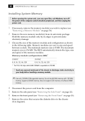
...(MB)* DIMM1 0, 8, 16, 32, 64, 128 DIMM2 0, 8, 16, 32, 64, 128 * The PCV-J100 ships with 100 MHz memory. Supports SDRAM memory. The minimum memory size is 256 MB. Do not mix 66 MHz...SDRAM is expandable to prevent staticelectricity damage. 3 Choose the size of the memory modules. 32 VAIO® Reference Manual Installing System Memory ! Touch any open files, exit Windows, turn off ...256 MB. ! Does not support EDO memory or buffered DIMM memory. 4 Disconnect the power cord from the computer. 5 Remove the side panel (see "Removing the Side Panel" on page 22). 6 Remove the front ...
...(MB)* DIMM1 0, 8, 16, 32, 64, 128 DIMM2 0, 8, 16, 32, 64, 128 * The PCV-J100 ships with 100 MHz memory. Supports SDRAM memory. The minimum memory size is 256 MB. Do not mix 66 MHz...SDRAM is expandable to prevent staticelectricity damage. 3 Choose the size of the memory modules. 32 VAIO® Reference Manual Installing System Memory ! Touch any open files, exit Windows, turn off ...256 MB. ! Does not support EDO memory or buffered DIMM memory. 4 Disconnect the power cord from the computer. 5 Remove the side panel (see "Removing the Side Panel" on page 22). 6 Remove the front ...

Reference Manual
Page 48
34 VAIO® Reference Manual 9 Align the memory module over the appropriate socket, noting the location of pin 1 on the module and pin 1 on each side of ...
34 VAIO® Reference Manual 9 Align the memory module over the appropriate socket, noting the location of pin 1 on the module and pin 1 on each side of ...
Reference Manual
Page 50
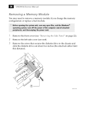
... VAIO® Reference Manual Removing a Memory Module You may need to the chassis and slide the diskette drive out about two inches (the attached cables limit this distance). 1 VOY001.VSD Before opening the system unit, save any open files, exit the Windows® operating system, turn off the power of the computer...
... VAIO® Reference Manual Removing a Memory Module You may need to the chassis and slide the diskette drive out about two inches (the attached cables limit this distance). 1 VOY001.VSD Before opening the system unit, save any open files, exit the Windows® operating system, turn off the power of the computer...

Reference Manual
Page 52
KY0069.VSD 38 VAIO® Reference Manual Removing a Slot Cover You remove a slot cover when you install an add-in card that occupies a previously-empty slot. 1 Disconnect the power cord from the computer. 2 Lay the system on its side. 3 Remove the side panel (see "Removing the Side Panel" on page 22). 4 Locate the slot whose cover you want to remove. 5 Remove the screw from the slot cover. 6 Remove the loose slot cover and retain it for future use.
KY0069.VSD 38 VAIO® Reference Manual Removing a Slot Cover You remove a slot cover when you install an add-in card that occupies a previously-empty slot. 1 Disconnect the power cord from the computer. 2 Lay the system on its side. 3 Remove the side panel (see "Removing the Side Panel" on page 22). 4 Locate the slot whose cover you want to remove. 5 Remove the screw from the slot cover. 6 Remove the loose slot cover and retain it for future use.

Reference Manual
Page 54
Before opening the system unit, save any open files, exit Windows, turn off the power of the computer and all attached peripherals, and then unplug the power cord. 1 Configure the jumpers on the new drive as a slave device (see "Removing the Side...must not require front panel access. Power connector Jumpers Drive connector KY0084.VSD 2 Disconnect the power cord from the computer. 3 Remove the side panel (see your drive's documentation for configuration instructions). 40 VAIO® Reference Manual Installing a 3½" Internal Hard Disk Drive Your system comes with an available bay to ...
Before opening the system unit, save any open files, exit Windows, turn off the power of the computer and all attached peripherals, and then unplug the power cord. 1 Configure the jumpers on the new drive as a slave device (see "Removing the Side...must not require front panel access. Power connector Jumpers Drive connector KY0084.VSD 2 Disconnect the power cord from the computer. 3 Remove the side panel (see your drive's documentation for configuration instructions). 40 VAIO® Reference Manual Installing a 3½" Internal Hard Disk Drive Your system comes with an available bay to ...

Reference Manual
Page 56
Align holes KY0083.VSD 8 Secure the drive to the drive holder using the two holes on each side of the drive holder. KY0085.VSD 42 VAIO® Reference Manual 7 Slide the new drive into the drive holder and align the holes on each side of the drive holder (screws are provided with the new drive). Do not overtighten the screws. 9 Connect the second drive connector to the new drive (see next diagram). 10 Connect the second power connector to the motherboard. Second power connector Second drive connector 11 Make sure the drive connector is connected securely to the new drive.
Align holes KY0083.VSD 8 Secure the drive to the drive holder using the two holes on each side of the drive holder. KY0085.VSD 42 VAIO® Reference Manual 7 Slide the new drive into the drive holder and align the holes on each side of the drive holder (screws are provided with the new drive). Do not overtighten the screws. 9 Connect the second drive connector to the new drive (see next diagram). 10 Connect the second power connector to the motherboard. Second power connector Second drive connector 11 Make sure the drive connector is connected securely to the new drive.


