
Operating Instructions (primary manual)
Page 9
... in the standby mode. 1/u (Power) DISPLAY 2 Turn the jog dial to select the preset number you want to tune in the Power Saving Mode. To reset the interval, repeat the same procedure.
... in the standby mode. 1/u (Power) DISPLAY 2 Turn the jog dial to select the preset number you want to tune in the Power Saving Mode. To reset the interval, repeat the same procedure.
Operating Instructions (primary manual)
Page 24
... is shorter than 20 tracks. 1 Insert a CD. 2 Press CD. 3 Press EDIT (EDIT/PTY on one side. "P" appears in the display and the total playing time resets to be recorded on both sides. 12 Press REC PAUSE/START. To stop recording Press π on the deck B or on the remote repeatedly. In...
... is shorter than 20 tracks. 1 Insert a CD. 2 Press CD. 3 Press EDIT (EDIT/PTY on one side. "P" appears in the display and the total playing time resets to be recorded on both sides. 12 Press REC PAUSE/START. To stop recording Press π on the deck B or on the remote repeatedly. In...
Operating Instructions (primary manual)
Page 41
... "STEREO" appears. The tape does not record nor play or there is a decrease in sound level. • The heads are magnetized. There is reset to turn the power back on page 39). Noise increases or the high frequencies are erased. • The record/playback heads are dirty. After pressing... is excessive wow or flutter, or the sound drops out. • The capstans or pinch rollers are magnetized. If other troubles not described above occur, reset the system as the preset stations, clock, and timer are magnetized. All the settings you made, such as follows: 1 Unplug the power cord. 2 ...
... "STEREO" appears. The tape does not record nor play or there is a decrease in sound level. • The heads are magnetized. There is reset to turn the power back on page 39). Noise increases or the high frequencies are erased. • The record/playback heads are dirty. After pressing... is excessive wow or flutter, or the sound drops out. • The capstans or pinch rollers are magnetized. If other troubles not described above occur, reset the system as the preset stations, clock, and timer are magnetized. All the settings you made, such as follows: 1 Unplug the power cord. 2 ...
Operating Instructions (primary manual)
Page 44
... Data System (RDS) 30 Radio stations presetting 8 tuning in 12 Recording a CD 11 a radio programme 14 timer recording 34 Repeat Play 19 Resetting the system 41 S Saving recordings 38 Selecting the audio emphasis 26 Setting the time 7 Shuffle Play 19 Sleep Timer 32 Sound adjustment 25 Speakers ... V, W, X, Y, Z Timer falling asleep to music 32 timer recording 34 waking up to music 33 Troubleshooting 39 Tuner 12, 30 Tuning interval 8 44 Sony Corporation Printed in Malaysia Index A Adjusting the graphic equalizer 28 the sound 25 the volume 11, 16 Aerials 5, 37 Automatic Source Selection 11, 13, 16...
... Data System (RDS) 30 Radio stations presetting 8 tuning in 12 Recording a CD 11 a radio programme 14 timer recording 34 Repeat Play 19 Resetting the system 41 S Saving recordings 38 Selecting the audio emphasis 26 Setting the time 7 Shuffle Play 19 Sleep Timer 32 Sound adjustment 25 Speakers ... V, W, X, Y, Z Timer falling asleep to music 32 timer recording 34 waking up to music 33 Troubleshooting 39 Tuner 12, 30 Tuning interval 8 44 Sony Corporation Printed in Malaysia Index A Adjusting the graphic equalizer 28 the sound 25 the volume 11, 16 Aerials 5, 37 Automatic Source Selection 11, 13, 16...
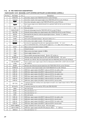
Service Manual
Page 9
... MEMORY] and ?/1 buttons simultaneously, and the display on the liquid crystal display. 5. Successively, the following three modes can be - The hot reset mode functions same as follows. 1) Move the optical pick-up to outside track, or turn the JOG dial counterclockwise. (3) Press the [TAPE]..., and [GROOVE] simultaneously, and the display on . Procedure: 1. SECTION 4 TEST MODE [CD Delivery Mode] • Execute only if connected to the HTC-NX1. • This mode moves the optical pick-up . Press the ?/1 button to turn the power ON. 2. Press the ?/1 button to the DEMO mode. ...
... MEMORY] and ?/1 buttons simultaneously, and the display on the liquid crystal display. 5. Successively, the following three modes can be - The hot reset mode functions same as follows. 1) Move the optical pick-up to outside track, or turn the JOG dial counterclockwise. (3) Press the [TAPE]..., and [GROOVE] simultaneously, and the display on . Procedure: 1. SECTION 4 TEST MODE [CD Delivery Mode] • Execute only if connected to the HTC-NX1. • This mode moves the optical pick-up . Press the ?/1 button to turn the power ON. 2. Press the ?/1 button to the DEMO mode. ...
Service Manual
Page 10
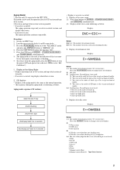
... section and tape deck section al- Press the [PLAY MODE] button to set the "ALL DISCS" mode, and press the [REPEAT] button to the HTC-NX1. The aging mode is blinking. 7. Tape Deck Section 9 Load the tapes into the decks A and B respectively. 3. Press the [CD] button to the "... tape deck section work in DISC5 tray. 2. To release from the aging mode, press the ?/1 button to turn the power OFF and operate the cold reset. (Refer to select the function "CD". 5. Aging mode sequence (CD section) : Open the disc1 tray Disc5 chucking Disc5 TOC read 4: Access 5: Play 6: Pause 7:...
... section and tape deck section al- Press the [PLAY MODE] button to set the "ALL DISCS" mode, and press the [REPEAT] button to the HTC-NX1. The aging mode is blinking. 7. Tape Deck Section 9 Load the tapes into the decks A and B respectively. 3. Press the [CD] button to the "... tape deck section work in DISC5 tray. 2. To release from the aging mode, press the ?/1 button to turn the power OFF and operate the cold reset. (Refer to select the function "CD". 5. Aging mode sequence (CD section) : Open the disc1 tray Disc5 chucking Disc5 TOC read 4: Access 5: Play 6: Pause 7:...
Service Manual
Page 12
... are dc with respect to normal produc- IC401 BA3830F R02 1 R01 2 LINE NF 3 LINE IN 4 REFERENCE CURRENT REFERENCE CURRENT - + REC NF 5 REC IN 6 - + RESET C 7 BIAS C 8 GND 9 RESET 18 RESET BAND PASS FILTER DET 17 F01 16 F02 15 F03 14 F04 13 F05 12 F06 11 REC LEVEL 10 VCC • Waveforms - BCE...
... are dc with respect to normal produc- IC401 BA3830F R02 1 R01 2 LINE NF 3 LINE IN 4 REFERENCE CURRENT REFERENCE CURRENT - + REC NF 5 REC IN 6 - + RESET C 7 BIAS C 8 GND 9 RESET 18 RESET BAND PASS FILTER DET 17 F01 16 F02 15 F03 14 F04 13 F05 12 F06 11 REC LEVEL 10 VCC • Waveforms - BCE...
Service Manual
Page 25
... (+5V) 17 NMI I Not used (fixed at "H" in this set 18 WAKE UP O Wakeup control signal output to the CPU on the HTC-NX1 "H" active 19 PHONES MUTE O Muting on/off control signal output terminal "L": muting on Not used (open) 20 RDS INT I RDS serial data transfer...S652 JOG) (A phase input) Jog dial pulse input from the rotary encoder (S651 VOLUME) (B phase input) Jog dial pulse input from the reset signal generator (IC502) "L": reset For several hundreds msec. Ground terminal 10 XCIN I Sub system clock input terminal (32.768 kHz) 11 XCOUT O Sub system clock output terminal...
... (+5V) 17 NMI I Not used (fixed at "H" in this set 18 WAKE UP O Wakeup control signal output to the CPU on the HTC-NX1 "H" active 19 PHONES MUTE O Muting on/off control signal output terminal "L": muting on Not used (open) 20 RDS INT I RDS serial data transfer...S652 JOG) (A phase input) Jog dial pulse input from the rotary encoder (S651 VOLUME) (B phase input) Jog dial pulse input from the reset signal generator (IC502) "L": reset For several hundreds msec. Ground terminal 10 XCIN I Sub system clock input terminal (32.768 kHz) 11 XCOUT O Sub system clock output terminal...
Service Manual
Page 77
... O Output terminal for red color) 29 IIC CLK I/O Communication data reading clock signal input or transfer clock signal output with the CPU in the STR-NX1/NX3 30 IIC DATA I Main system clock input terminal (16 MHz) 16 VDD - Pin Name I/O Description 1 CD DATA O Serial data output to the ...color) 38 LED G1 O LED drive signal output of the key illumination LED (D201 to D204, D218 to D225) "H": LED on 21 SENSE I System reset signal input from the CXD2587Q (IC101) on the CD block 8 BYTE I External data bus line byte selection signal input terminal Fixed at "L" in the STR...
... O Output terminal for red color) 29 IIC CLK I/O Communication data reading clock signal input or transfer clock signal output with the CPU in the STR-NX1/NX3 30 IIC DATA I Main system clock input terminal (16 MHz) 16 VDD - Pin Name I/O Description 1 CD DATA O Serial data output to the ...color) 38 LED G1 O LED drive signal output of the key illumination LED (D201 to D204, D218 to D225) "H": LED on 21 SENSE I System reset signal input from the CXD2587Q (IC101) on the CD block 8 BYTE I External data bus line byte selection signal input terminal Fixed at "L" in the STR...


