Operating Instructions (primary manual)
Page 2
... to Part 15 of the following measures: - The MHC-NX1 consist of the FCC Rules. A/V control amplifier STR-NX1 - CD player/Stereo cassette deck HTC-NX1 - Refer servicing to which can radiate radio frequency energy and, if not installed and used in accordance with this equipment. This appliance is encouraged to try to rain or moisture. However, there is connected. - Increase the separation between the equipment and receiver. - Connect...
... to Part 15 of the following measures: - The MHC-NX1 consist of the FCC Rules. A/V control amplifier STR-NX1 - CD player/Stereo cassette deck HTC-NX1 - Refer servicing to which can radiate radio frequency energy and, if not installed and used in accordance with this equipment. This appliance is encouraged to try to rain or moisture. However, there is connected. - Increase the separation between the equipment and receiver. - Connect...
Operating Instructions (primary manual)
Page 3
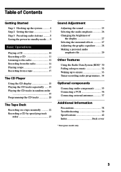
... 4 Step 2: Setting the time 7 Step 3: Presetting radio stations .......... 8 Saving the power in standby mode ..... 9 Basic Operations Playing a CD 10 Recording a CD 11 Listening to the radio 12 Recording from the radio 14 Playing a tape 15 Recording from a tape 17 The CD Player Using the CD display 18 Playing the CD tracks repeatedly ...... 19 Playing the CD tracks in random order 19 Programming the CD tracks 20 The Tape Deck Recording on a tape manually 22 Recording...
... 4 Step 2: Setting the time 7 Step 3: Presetting radio stations .......... 8 Saving the power in standby mode ..... 9 Basic Operations Playing a CD 10 Recording a CD 11 Listening to the radio 12 Recording from the radio 14 Playing a tape 15 Recording from a tape 17 The CD Player Using the CD display 18 Playing the CD tracks repeatedly ...... 19 Playing the CD tracks in random order 19 Programming the CD tracks 20 The Tape Deck Recording on a tape manually 22 Recording...
Operating Instructions (primary manual)
Page 6
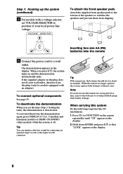
... DEMO (STANDBY) (other models) while the system is deactivated. Tip You can reinforce the bass sound by connecting an optional super woofer to the super woofer connector. ] } } ] Tip With normal use the remote for a long period of time, remove the batteries to avoid possible damage from battery leakage. When the remote no longer operates the system, replace both batteries with a voltage selector, set the time (Step 2: Setting...
... DEMO (STANDBY) (other models) while the system is deactivated. Tip You can reinforce the bass sound by connecting an optional super woofer to the super woofer connector. ] } } ] Tip With normal use the remote for a long period of time, remove the batteries to avoid possible damage from battery leakage. When the remote no longer operates the system, replace both batteries with a voltage selector, set the time (Step 2: Setting...

Operating Instructions (primary manual)
Page 9
... demo mode. • 1/u indicator and timer indicator (when the timer is set) light up even in the Power Saving Mode. • The timer works in the standby mode. 1/u (Power) DISPLAY 2 Turn the jog dial to select the preset number you unplug the power cord or if a power failure occurs. - + 0 ) ≠ + - + g POWER SAVE/DEMO (STANDBY) / Press POWER SAVE/DEMO (STANDBY) when the power is factory set the time in the Power Saving Mode. • One Touch Play function does not work in a station with a weak signal...
... demo mode. • 1/u indicator and timer indicator (when the timer is set) light up even in the Power Saving Mode. • The timer works in the standby mode. 1/u (Power) DISPLAY 2 Turn the jog dial to select the preset number you unplug the power cord or if a power failure occurs. - + 0 ) ≠ + - + g POWER SAVE/DEMO (STANDBY) / Press POWER SAVE/DEMO (STANDBY) when the power is factory set the time in the Power Saving Mode. • One Touch Play function does not work in a station with a weak signal...
Operating Instructions (primary manual)
Page 11
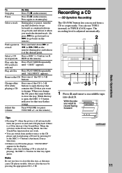
... a DISC 1~5 button (or D. Play all CDs Press PLAY MODE repeatedly until "1 DISC" appears. Note Do not use TYPE I (normal) or TYPE II (CrO2) tapes. You can switch from a CD to the CD player and start playing a CD just by pressing the appropriate CD 1~5 §. With the side you have selected Press PLAY MODE repeatedly until "ALL DISCS" appears. Select a track During play Press π (p on the remote) during play . Play...
... a DISC 1~5 button (or D. Play all CDs Press PLAY MODE repeatedly until "1 DISC" appears. Note Do not use TYPE I (normal) or TYPE II (CrO2) tapes. You can switch from a CD to the CD player and start playing a CD just by pressing the appropriate CD 1~5 §. With the side you have selected Press PLAY MODE repeatedly until "ALL DISCS" appears. Select a track During play Press π (p on the remote) during play . Play...
Operating Instructions (primary manual)
Page 13
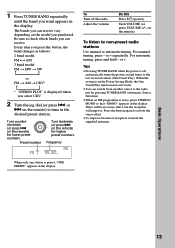
... the remote) to the radio just by pressing TUNER BAND (Automatic Source Selection). • When an FM programme is in the Power Saving Mode, the One Touch Play function does not work. • You can switch from another source to tune in the display. or + repeatedly. When the system is noisy, press STEREO/ MONO so that "MONO" appears in the desired preset station. Every time you press the button...
... the remote) to the radio just by pressing TUNER BAND (Automatic Source Selection). • When an FM programme is in the Power Saving Mode, the One Touch Play function does not work. • You can switch from another source to tune in the display. or + repeatedly. When the system is noisy, press STEREO/ MONO so that "MONO" appears in the desired preset station. Every time you press the button...
Operating Instructions (primary manual)
Page 16
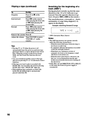
... the power is off . 16 When the unit is placed near a television. (In this Stop play is recorded with DOLBY NR, you want to go forward. When there are continuous sections of extremely low level or low frequency sound (like those of songs being skipped (1~9) appear in the display. Turn the opposite direction to play Press π (or p on the remote while playing the...
... the power is off . 16 When the unit is placed near a television. (In this Stop play is recorded with DOLBY NR, you want to go forward. When there are continuous sections of extremely low level or low frequency sound (like those of songs being skipped (1~9) appear in the display. Turn the opposite direction to play Press π (or p on the remote while playing the...
Operating Instructions (primary manual)
Page 33
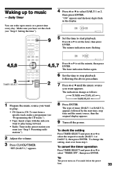
... 3: Presetting radio stations"). 2 Adjust the volume. 3 Press CLOCK/TIMER. "SET (DAILY 1)" appears. 8 Press ENTER. To cancel the timer operation Press TIMER SELECT and press V or v to music at a preset time every day. Make sure you want to play facing forward. • Radio: Tune in the display. 1 4,5,8 3 TIMER SELECT · ª· ª· =+ p 0 ) P V B b v · p 9 5 Set the time to select DAILY 1 or 2, then press ENTER. To change as follows: n TUNER ˜ CD PLAY N n TAPE PLAY...
... 3: Presetting radio stations"). 2 Adjust the volume. 3 Press CLOCK/TIMER. "SET (DAILY 1)" appears. 8 Press ENTER. To cancel the timer operation Press TIMER SELECT and press V or v to music at a preset time every day. Make sure you want to play facing forward. • Radio: Tune in the display. 1 4,5,8 3 TIMER SELECT · ª· ª· =+ p 0 ) P V B b v · p 9 5 Set the time to select DAILY 1 or 2, then press ENTER. To change as follows: n TUNER ˜ CD PLAY N n TAPE PLAY...

Operating Instructions (primary manual)
Page 39
... 2: Setting the time" - "Step 3: Presetting radio stations" If you run into the SPEAKER jack. Otherwise the tape may get entangled in the parts of the speaker cord into any problem using a tape longer than half a day. The tape may get entangled in the tape deck. For details, refer to the instructions of the demagnetizing cassette. Demagnetizing the tape heads Demagnetize the tape heads and the metal parts that the power cord is no audio output...
... 2: Setting the time" - "Step 3: Presetting radio stations" If you run into the SPEAKER jack. Otherwise the tape may get entangled in the parts of the speaker cord into any problem using a tape longer than half a day. The tape may get entangled in the tape deck. For details, refer to the instructions of the demagnetizing cassette. Demagnetizing the tape heads Demagnetize the tape heads and the metal parts that the power cord is no audio output...
Operating Instructions (primary manual)
Page 40
... speaker farther away from TV set once, then turn it on top of the CD. jacks are connected correctly. Press and hold 0 to the stereo system. "PROTECT" and "PUSH POWER" appear alternately. •A strong signal was input. Move the stereo system away from the speakers or change the direction of the system's sensor. •The batteries have reached the end of the CD player/stereo cassette deck. Speakers Sound...
... speaker farther away from TV set once, then turn it on top of the CD. jacks are connected correctly. Press and hold 0 to the stereo system. "PROTECT" and "PUSH POWER" appear alternately. •A strong signal was input. Move the stereo system away from the speakers or change the direction of the system's sensor. •The batteries have reached the end of the CD player/stereo cassette deck. Speakers Sound...
Operating Instructions (primary manual)
Page 42
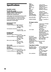
... Front Speaker: DIN power output (rated) 90 + 90 watts (6 ohms at 1 kHz, DIN) Continuous RMS power output (reference) 110 + 110 watts (6 ohms at 1 kHz, 10% THD) Total harmonics distortion Less than 90 dB CD DIGITAL OUT (Square optical connector jack, rear panel) Wavelength 660 nm Output Level -18 dBm Tape player section Recording system Frequency response (DOLBY NR OFF) Wow and flutter 4-track 2-channel stereo 40 - 13,000 Hz (±3 dB), using Sony TYPE...
... Front Speaker: DIN power output (rated) 90 + 90 watts (6 ohms at 1 kHz, DIN) Continuous RMS power output (reference) 110 + 110 watts (6 ohms at 1 kHz, 10% THD) Total harmonics distortion Less than 90 dB CD DIGITAL OUT (Square optical connector jack, rear panel) Wavelength 660 nm Output Level -18 dBm Tape player section Recording system Frequency response (DOLBY NR OFF) Wow and flutter 4-track 2-channel stereo 40 - 13,000 Hz (±3 dB), using Sony TYPE...
Operating Instructions (primary manual)
Page 44
... Repeat Play 19 Resetting the system 41 S Saving recordings 38 Selecting the audio emphasis 26 Setting the time 7 Shuffle Play 19 Sleep Timer 32 Sound adjustment 25 Speakers 36 Station name 30 T, U, V, W, X, Y, Z Timer falling asleep to music 32 timer recording 34 waking up to music 33 Troubleshooting 39 Tuner 12, 30 Tuning interval 8 44 Sony Corporation Printed in Malaysia Index A Adjusting the graphic equalizer 28 the sound 25 the volume 11...
... Repeat Play 19 Resetting the system 41 S Saving recordings 38 Selecting the audio emphasis 26 Setting the time 7 Shuffle Play 19 Sleep Timer 32 Sound adjustment 25 Speakers 36 Station name 30 T, U, V, W, X, Y, Z Timer falling asleep to music 32 timer recording 34 waking up to music 33 Troubleshooting 39 Tuner 12, 30 Tuning interval 8 44 Sony Corporation Printed in Malaysia Index A Adjusting the graphic equalizer 28 the sound 25 the volume 11...
Service Manual
Page 1
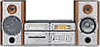
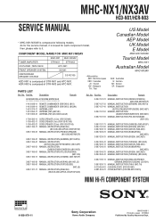
... G : German KR : Korean SP : Singapore Ref. No. As for each component model, then, please refer to it. MHC-NX1/NX3AV HCD-NX1/HCR-NX3 SERVICE MANUAL • MHC-NX1/NX3AV is composed of STR-NX1 and HTC-NX1. COMPONENT MODEL NAME FOR MHC-NX1/NX3AV US Model Canadian Model AEP Model UK Model E Model MHC-NX1/NX3AV TUNER,AMPLIFIER MHC-NX1 STR-NX1 MHC-NX3AV STR-NX3 Tourist Model MHC-NX1 CD PLAYER ,TAPE DECK FRONT SPEAKER SYSTEM CENTER/REAR SPEAKER SYSTEM HTC-NX1 SS-NX1 SS-RC100 HCD-NX1 is composed of following models. Part No. Part No.
... G : German KR : Korean SP : Singapore Ref. No. As for each component model, then, please refer to it. MHC-NX1/NX3AV HCD-NX1/HCR-NX3 SERVICE MANUAL • MHC-NX1/NX3AV is composed of STR-NX1 and HTC-NX1. COMPONENT MODEL NAME FOR MHC-NX1/NX3AV US Model Canadian Model AEP Model UK Model E Model MHC-NX1/NX3AV TUNER,AMPLIFIER MHC-NX1 STR-NX1 MHC-NX3AV STR-NX3 Tourist Model MHC-NX1 CD PLAYER ,TAPE DECK FRONT SPEAKER SYSTEM CENTER/REAR SPEAKER SYSTEM HTC-NX1 SS-NX1 SS-RC100 HCD-NX1 is composed of following models. Part No. Part No.
Service Manual
Page 4
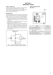
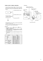
... SAFETY CHECK-OUT After correcting the original service problem, perform the following safety check before releasing the set to check AC leakage. 3 Using an AC voltmeter to the customer: Check the antenna terminals, metal trim, "metallized" knobs, screws, and all battery operated digital multimeters that is suitable. A battery-operated AC milliammeter. Rear Panel - Leakage current can be measured by means...
... SAFETY CHECK-OUT After correcting the original service problem, perform the following safety check before releasing the set to check AC leakage. 3 Using an AC voltmeter to the customer: Check the antenna terminals, metal trim, "metallized" knobs, screws, and all battery operated digital multimeters that is suitable. A battery-operated AC milliammeter. Rear Panel - Leakage current can be measured by means...
Service Manual
Page 5
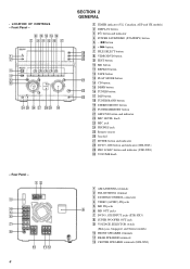
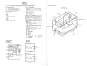
... ANTENNA terminals 2 FM ANTENNA terminal 3 SYSTEM CONTROL connector 4 VIDEO (AUDIO) IN jacks 5 MD IN jacks 9 6 MD OUT jacks 7 DVD 5.1CH INPUT jacks (STR-NX3) 8 SUPER WOOFER OUT jack 9 VOLTAGE SELECTOR switch (Malaysia, Singapore and Tourist models) q; Front Panel - 8 q; Rear Panel - 12 3 4 5 6 7 8 q; FRONT SPEAKER terminals qa REAR SPEAKER terminals qs CENTER SPEAKER terminals (STR-NX3) VOLUME knob - MD button qa REPEAT button qs TAPE button wa qd PLAY MODE button qf CD button qg DBFB button ws qh TUNER button wd qj DSP button qk TUNER BAND button ql STEREO...
... ANTENNA terminals 2 FM ANTENNA terminal 3 SYSTEM CONTROL connector 4 VIDEO (AUDIO) IN jacks 5 MD IN jacks 9 6 MD OUT jacks 7 DVD 5.1CH INPUT jacks (STR-NX3) 8 SUPER WOOFER OUT jack 9 VOLTAGE SELECTOR switch (Malaysia, Singapore and Tourist models) q; Front Panel - 8 q; Rear Panel - 12 3 4 5 6 7 8 q; FRONT SPEAKER terminals qa REAR SPEAKER terminals qs CENTER SPEAKER terminals (STR-NX3) VOLUME knob - MD button qa REPEAT button qs TAPE button wa qd PLAY MODE button qf CD button qg DBFB button ws qh TUNER button wd qj DSP button qk TUNER BAND button ql STEREO...
Service Manual
Page 9
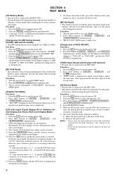
... is changed over. [VIDEO input, Record and CD play in the RAM to the customer. Turn the power ON or set to the DEMO mode. 2. Press three buttons of [ENTER] , [DISPLAY] , and [TUNER MEMORY] simultaneously. 3. if turn the power ON. 2. Turn the power ON or set is displayed on the liquid crystal display. 5. The set to the DEMO mode. 2. Procedure: 1. To release from this mode, perform as step 2, or remove the power cord. [MC Hot Reset...
... is changed over. [VIDEO input, Record and CD play in the RAM to the customer. Turn the power ON or set to the DEMO mode. 2. Press three buttons of [ENTER] , [DISPLAY] , and [TUNER MEMORY] simultaneously. 3. if turn the power ON. 2. Turn the power ON or set is displayed on the liquid crystal display. 5. The set to the DEMO mode. 2. Procedure: 1. To release from this mode, perform as step 2, or remove the power cord. [MC Hot Reset...
Service Manual
Page 10
... (Play) 8:Manual search (Pause)3. Tape Deck Section 9 To release from the aging mode, press the ?/1 button to turn the power OFF and operate the cold reset. (Refer to select the function "CD". 5. ternately. • If an error occurred, stop display which that section. 2. Display EMC**EDC** Notes: EMC**: The number of [ENTER] , [POWER SAVE/DEMO] , and [TUNER BAND] simultaneously. 6. Procedure: 1. Load the tapes into the decks A and B respectively. 3. The aging mode is blinking...
... (Play) 8:Manual search (Pause)3. Tape Deck Section 9 To release from the aging mode, press the ?/1 button to turn the power OFF and operate the cold reset. (Refer to select the function "CD". 5. ternately. • If an error occurred, stop display which that section. 2. Display EMC**EDC** Notes: EMC**: The number of [ENTER] , [POWER SAVE/DEMO] , and [TUNER BAND] simultaneously. 6. Procedure: 1. Load the tapes into the decks A and B respectively. 3. The aging mode is blinking...
Service Manual
Page 12
... normal produc- tion tolerances. • Circled numbers refer to ground under no mark : TUNER (FM) • Voltages are not indicated except for safety. F : TUNER (FM) E : TAPE PLAYBACK G : RECORD J : CD PLAY N : MIC INPUT • Abbreviation AUS : Australian model MY : Malaysia model CND : Canadian model SP : Singapore model JE : Tourist model TH : Thai model KR : Korean model • IC Block Diagram - Note on the conductor side. •...
... normal produc- tion tolerances. • Circled numbers refer to ground under no mark : TUNER (FM) • Voltages are not indicated except for safety. F : TUNER (FM) E : TAPE PLAYBACK G : RECORD J : CD PLAY N : MIC INPUT • Abbreviation AUS : Australian model MY : Malaysia model CND : Canadian model SP : Singapore model JE : Tourist model TH : Thai model KR : Korean model • IC Block Diagram - Note on the conductor side. •...
Service Manual
Page 25
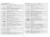
... the M62464FP (IC201) (Used for the STR-NX3 only) 26 STK POWER O Power amplifier on/off selection signal output terminal "L": standby mode, "H": on 27 SPEAKER PROTECT I Protect on/off detection signal input from the speaker protect circuit "L": protect on (Used for the US, Canadian, AEP and UK models only) LED drive signal output of the PRO LOGIC indicator (D633) "H": LED on , "H": protect off (normal), "H": sync bass high Not used (open) Not used (open) Not used (fixed at "L") 37 LCD CLK...
... the M62464FP (IC201) (Used for the STR-NX3 only) 26 STK POWER O Power amplifier on/off selection signal output terminal "L": standby mode, "H": on 27 SPEAKER PROTECT I Protect on/off detection signal input from the speaker protect circuit "L": protect on (Used for the US, Canadian, AEP and UK models only) LED drive signal output of the PRO LOGIC indicator (D633) "H": LED on , "H": protect off (normal), "H": sync bass high Not used (open) Not used (open) Not used (fixed at "L") 37 LCD CLK...
Service Manual
Page 46
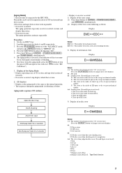
..., use the Power Feed Jig (PFJ1) and Relay Connector Jig. Press three buttons of attachment to the PreMain amplifier and Tuner Unit (STR-NX1/NX3) of respective functions and buttons is as follows. SYSTEM CONTROL terminal Set Pre-Main AMP and Tuner Unit SYSTEM CONTROL terminal Connector cable (19P) Connection: Connector cable (17P) of s (DECK B), A (DISC 1), and s (CD) simultaneously. 2. FF/AMS + button s (DECK A), S (CD) s (DECK A), s (CD) s (DECK B), S (CD) s (DECK B), s (CD) s (CD), g (DECK A) s (CD), G (DECK A) s (CD), g (DECK B) s (CD), G (DECK B) system cable...
..., use the Power Feed Jig (PFJ1) and Relay Connector Jig. Press three buttons of attachment to the PreMain amplifier and Tuner Unit (STR-NX1/NX3) of respective functions and buttons is as follows. SYSTEM CONTROL terminal Set Pre-Main AMP and Tuner Unit SYSTEM CONTROL terminal Connector cable (19P) Connection: Connector cable (17P) of s (DECK B), A (DISC 1), and s (CD) simultaneously. 2. FF/AMS + button s (DECK A), S (CD) s (DECK A), s (CD) s (DECK B), S (CD) s (DECK B), s (CD) s (CD), g (DECK A) s (CD), G (DECK A) s (CD), g (DECK B) s (CD), G (DECK B) system cable...


