
Installation Manual
Page 4
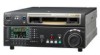
..." oder nach längerer Gebrauchsdauer der Batterien "nicht mehr einwandfrei funktioniert". Entladen sind Batterien in Taiwan only 2 (P) HDW-1800/D1800 Install the equipment while taking the operating temperature of the equipment into consideration For the operating temperature of the equipment, refer to obtain proper exhaust and radiation of the rack When this product is... this product is installed in a rack and is supplied power from walls in a rack, please make sure that the internal air ambient temperature of the Operation Manual. 6.
..." oder nach längerer Gebrauchsdauer der Batterien "nicht mehr einwandfrei funktioniert". Entladen sind Batterien in Taiwan only 2 (P) HDW-1800/D1800 Install the equipment while taking the operating temperature of the equipment into consideration For the operating temperature of the equipment, refer to obtain proper exhaust and radiation of the rack When this product is... this product is installed in a rack and is supplied power from walls in a rack, please make sure that the internal air ambient temperature of the Operation Manual. 6.
Installation Manual
Page 5
...HDW-1800/D1800 1 (E) Installation 1-1. Power Supply 1-2 (E) 1-4-1. Rack Mounting 1-4 (E) 1-7. Switching Search Dial Mode 1-19 (E) 1-14. VTR Constant Values Settings of Destination Selection Mode 1-17 (E) 1-12. Switch Settings on Circuit Boards 1-15 (E) 1-10-1. Supplied Accessories 1-1 (E) 1-3. Operating... Conditions 1-1 (E) 1-4. Matching Connectors and Cables 1-9 (E) 1-8. Signal Inputs and Outputs 1-10 (E) 1-9. APR-80 Board 1-15 (E) 1-11. Settings and Adjustment when External Equipment is Connected 1-21 (E) 1-15-1. Operation Mode Settings 1-...
...HDW-1800/D1800 1 (E) Installation 1-1. Power Supply 1-2 (E) 1-4-1. Rack Mounting 1-4 (E) 1-7. Switching Search Dial Mode 1-19 (E) 1-14. VTR Constant Values Settings of Destination Selection Mode 1-17 (E) 1-12. Switch Settings on Circuit Boards 1-15 (E) 1-10-1. Supplied Accessories 1-1 (E) 1-3. Operating... Conditions 1-1 (E) 1-4. Matching Connectors and Cables 1-9 (E) 1-8. Signal Inputs and Outputs 1-10 (E) 1-9. APR-80 Board 1-15 (E) 1-11. Settings and Adjustment when External Equipment is Connected 1-21 (E) 1-15-1. Operation Mode Settings 1-...
Installation Manual
Page 6
... information that is the installation manual of the HD Digital Videocassette Recorder HDW-1800/D1800. Manual Structure Purpose of this manual This manual is required to search for semiconductors used together with this unit.) This manual is necessary for application and operation (and installation) of this unit. . Operation Manual (Supplied with the CD-ROM. Maintenance Manual (Available on request) This "Semiconductor...
... information that is the installation manual of the HD Digital Videocassette Recorder HDW-1800/D1800. Manual Structure Purpose of this manual This manual is required to search for semiconductors used together with this unit.) This manual is necessary for application and operation (and installation) of this unit. . Operation Manual (Supplied with the CD-ROM. Maintenance Manual (Available on request) This "Semiconductor...
Installation Manual
Page 7
... of this unit is shown on Connector Panel 1-10. Areas where the unit will be exposed to avoid: . The operation manual is required to prevent internal heat build-up. Do not reuse the packing materials. Rack Mounting *Connection 1-7. Areas with sufficient...magnetic field. . Refer to vibration. . Tilt allowance: Within 30d (Do not slant the front and rear of each flow. HDW-1800/D1800 1-1 (E) Operating Conditions 1-4. Removing/Reattaching Lower Control Panel Unit 1-13. Areas near heat sources. . Dusty areas or areas subject to each section...
... of this unit is shown on Connector Panel 1-10. Areas where the unit will be exposed to avoid: . The operation manual is required to prevent internal heat build-up. Do not reuse the packing materials. Rack Mounting *Connection 1-7. Areas with sufficient...magnetic field. . Refer to vibration. . Tilt allowance: Within 30d (Do not slant the front and rear of each flow. HDW-1800/D1800 1-1 (E) Operating Conditions 1-4. Removing/Reattaching Lower Control Panel Unit 1-13. Areas near heat sources. . Dusty areas or areas subject to each section...
Installation Manual
Page 20
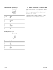
Refer to perform the following setup. Analog audio input level/600 Z termination switches . 75 Z termination switch of Parts" for setup. . GND RM TX (+) RM RX (_) GND HDV IN (OPTION): 6-pin External view 1 2 3 4 5 6 Pin No. 1 2 3 4 5 6 Signal VP VG NTPB TPB NTPA TPA 1-9. VIDEO CONTROL: 9-pin (female) External view 5 1 Pin No. 1 2 3 4 5 6 7 8 9 96 Signal GND RM TX (_) RM RX (+) GND -- Switch Settings on Connector Panel When the unit is installed, be sure to the operation manual "Section 2 Location and Function of reference video input 1-14 (E) HDW-1800/D1800
Refer to perform the following setup. Analog audio input level/600 Z termination switches . 75 Z termination switch of Parts" for setup. . GND RM TX (+) RM RX (_) GND HDV IN (OPTION): 6-pin External view 1 2 3 4 5 6 Pin No. 1 2 3 4 5 6 Signal VP VG NTPB TPB NTPA TPA 1-9. VIDEO CONTROL: 9-pin (female) External view 5 1 Pin No. 1 2 3 4 5 6 7 8 9 96 Signal GND RM TX (_) RM RX (+) GND -- Switch Settings on Connector Panel When the unit is installed, be sure to the operation manual "Section 2 Location and Function of reference video input 1-14 (E) HDW-1800/D1800
Installation Manual
Page 23
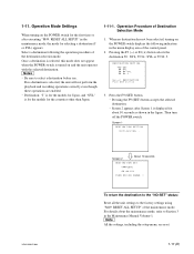
1-11. m . If no destination has not been selected, turning on and the unit operates with the selected destination. HDW-1800/D1800 Screen 2 About 10 seconds DESTINATION SET COMPLETE 59.94:SYL TURN OFF/ON POWER !! n All the settings,...button accepts the selected destination. . Then turn off the POWER switch. Select a destination following indication in the Maintenance Manual Volume-1. Screen 1 DESTINATION SETTING INITIALIZING... Operation Mode Settings When turning on the POWER switch for about the maintenance mode, refer to select a destination before use....
1-11. m . If no destination has not been selected, turning on and the unit operates with the selected destination. HDW-1800/D1800 Screen 2 About 10 seconds DESTINATION SET COMPLETE 59.94:SYL TURN OFF/ON POWER !! n All the settings,...button accepts the selected destination. . Then turn off the POWER switch. Select a destination following indication in the Maintenance Manual Volume-1. Screen 1 DESTINATION SETTING INITIALIZING... Operation Mode Settings When turning on the POWER switch for about the maintenance mode, refer to select a destination before use....
Installation Manual
Page 31
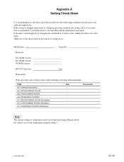
.... RS-232C baud rate: bps . HDW-1800/D1800 A-1 (E) For details, refer to the unit when check, maintenance and repair. It is recommended to attach the sheets to the maintenance manual volume 1. If the unit is used frequently by changing operating condition, the setting can be reset easily...making the sheets are convenient. (Make use of the check sheets in prevention of setting error.) Model name: Serial No . ITEM H01: OPERATION HOURS H02: DRUM RUNNING HOURS H03: TAPE RUNNING HOURS H04: THREADING COUNTER H12: DRUM RUNNING HOURS (Resettable) H13: TAPE RUNNING HOURS (...
.... RS-232C baud rate: bps . HDW-1800/D1800 A-1 (E) For details, refer to the unit when check, maintenance and repair. It is recommended to attach the sheets to the maintenance manual volume 1. If the unit is used frequently by changing operating condition, the setting can be reset easily...making the sheets are convenient. (Make use of the check sheets in prevention of setting error.) Model name: Serial No . ITEM H01: OPERATION HOURS H02: DRUM RUNNING HOURS H03: TAPE RUNNING HOURS H04: THREADING COUNTER H12: DRUM RUNNING HOURS (Resettable) H13: TAPE RUNNING HOURS (...


