Instruction Manual
Page 4
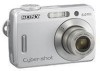
... Check Upon completion of time, unplug it from the wall outlet and refer servicing to qualified service personnel. Replacement parts When replacement parts are specified in fire, electric shock, or other hazards. When the power cord or plug is left unattended and unused for ..., ask the service technician to perform routine safety checks (as specified by the manufacturer that are required, be sure the service technician has used replacement parts specified by the manufacturer) to determine that the set . - Servicing Do not attempt to service the set during a lightning storm, or when...
... Check Upon completion of time, unplug it from the wall outlet and refer servicing to qualified service personnel. Replacement parts When replacement parts are specified in fire, electric shock, or other hazards. When the power cord or plug is left unattended and unused for ..., ask the service technician to perform routine safety checks (as specified by the manufacturer that are required, be sure the service technician has used replacement parts specified by the manufacturer) to determine that the set . - Servicing Do not attempt to service the set during a lightning storm, or when...
Service Manual
Page 1
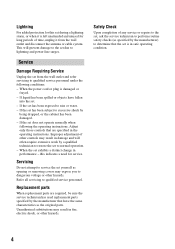
...main board, or main frame assembly failure, contact your local Sony Service Headquarter for safety. SERVICE MANUAL Ver. 1.3 2007.08 Revision History How to use Acrobat Reader Internal memory ON BOARD DSC-S500 US Model Canadian Model AEP Model UK Model E Model Australian ... Link SPECIFICATIONS SERVICE NOTE DISASSEMBLY BLOCK DIAGRAMS REPAIR PARTS LIST The components identified by Kohda TEC DIGITAL STILL CAMERA DSC-S500 9-852-124-12 Sony EMCS Co. 2007H0800-1 © 2007.08 Published by mark 0 or dotted line with part number specified. Replace only with mark 0 are critical for the ...
...main board, or main frame assembly failure, contact your local Sony Service Headquarter for safety. SERVICE MANUAL Ver. 1.3 2007.08 Revision History How to use Acrobat Reader Internal memory ON BOARD DSC-S500 US Model Canadian Model AEP Model UK Model E Model Australian ... Link SPECIFICATIONS SERVICE NOTE DISASSEMBLY BLOCK DIAGRAMS REPAIR PARTS LIST The components identified by Kohda TEC DIGITAL STILL CAMERA DSC-S500 9-852-124-12 Sony EMCS Co. 2007H0800-1 © 2007.08 Published by mark 0 or dotted line with part number specified. Replace only with mark 0 are critical for the ...
Service Manual
Page 3
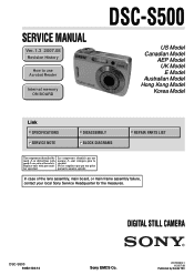
... OR IN SUPPLEMENTS PUBLISHED BY SONY. Look for parts which, through functioning, show obvious signs of unleaded solder are "pinched" or contact high-wattage resistors. ATTENTION AU COMPOSANT AYANT RAPPORT À LA SÉCURITÉ! Look for unauthorized replacement parts, particularly transistors, that no ... size.) 3. Point them out to the solder joint for a slightly longer time. Caution: The printed pattern (copper foil) may DSC-S500 also be careful! • Strong viscosity circuit board (within 3 times). Check the area of explosion if battery is applied for ...
... OR IN SUPPLEMENTS PUBLISHED BY SONY. Look for parts which, through functioning, show obvious signs of unleaded solder are "pinched" or contact high-wattage resistors. ATTENTION AU COMPOSANT AYANT RAPPORT À LA SÉCURITÉ! Look for unauthorized replacement parts, particularly transistors, that no ... size.) 3. Point them out to the solder joint for a slightly longer time. Caution: The printed pattern (copper foil) may DSC-S500 also be careful! • Strong viscosity circuit board (within 3 times). Check the area of explosion if battery is applied for ...
Service Manual
Page 12
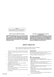
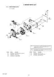
... Microphone Assy DSC-S500 4-3 Description A-1205-305-A Stroboscope Block Assy (Note 2) 2-699-484-01 Holder, LCD A-1209-107-A TFT-LCD (Note 2) A-1209-106-A PC Board, Switch (Note 1) In case of the lens assembly, main board, or main frame assembly failure, contact your local Sony Service Headquarter ...for the measures. (Note 2) The adjustment is not required after replacing the stroboscope block assembly or LCD. No. 105 106 107 Part No. Ref. MAIN FRAME BLOCK ns: not supplied 104 101 ...
... Microphone Assy DSC-S500 4-3 Description A-1205-305-A Stroboscope Block Assy (Note 2) 2-699-484-01 Holder, LCD A-1209-107-A TFT-LCD (Note 2) A-1209-106-A PC Board, Switch (Note 1) In case of the lens assembly, main board, or main frame assembly failure, contact your local Sony Service Headquarter ...for the measures. (Note 2) The adjustment is not required after replacing the stroboscope block assembly or LCD. No. 105 106 107 Part No. Ref. MAIN FRAME BLOCK ns: not supplied 104 101 ...

