
Instruction Manual
Page 3
... a cloth or other ). Use only a cart, stand, tripod, bracket, or table recommended by the manufacturer, as they may touch dangerous voltage points or short out parts that it is a safety feature. Never cover the slots and openings with water for necessary ventilation. Never block the slots and openings by forcing it...
... a cloth or other ). Use only a cart, stand, tripod, bracket, or table recommended by the manufacturer, as they may touch dangerous voltage points or short out parts that it is a safety feature. Never cover the slots and openings with water for necessary ventilation. Never block the slots and openings by forcing it...
Instruction Manual
Page 4
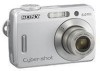
...only those controls that are required, be sure the service technician has used replacement parts specified by the manufacturer) to normal operation. - Servicing Do not attempt to service the set . - Replacement parts When replacement parts are specified in damage and will prevent damage to the set , ask the ... often require extensive work by a qualified technician to restore the set to determine that have fallen into the set yourself as the original parts. If the set is in performance - Lightning For added protection for this indicates a need for long periods of time, unplug it ...
...only those controls that are required, be sure the service technician has used replacement parts specified by the manufacturer) to normal operation. - Servicing Do not attempt to service the set . - Replacement parts When replacement parts are specified in damage and will prevent damage to the set , ask the ... often require extensive work by a qualified technician to restore the set to determine that have fallen into the set yourself as the original parts. If the set is in performance - Lightning For added protection for this indicates a need for long periods of time, unplug it ...
Instruction Manual
Page 5
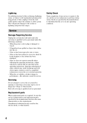
... Consult the dealer or an experienced radio/TV technician for help prevent potential negative consequences for a Class B digital device, pursuant to radio or television reception, which can radiate radio frequency energy and, if not installed and...Equipment (Applicable in the European Union and other European countries with the limits for a digital device pursuant to comply with part 15 of this first For Customers in the EMC Directive for the recycling of the ... information about recycling of this equipment. Read this camera. Reorient or relocate the receiving antenna. -
... Consult the dealer or an experienced radio/TV technician for help prevent potential negative consequences for a Class B digital device, pursuant to radio or television reception, which can radiate radio frequency energy and, if not installed and...Equipment (Applicable in the European Union and other European countries with the limits for a digital device pursuant to comply with part 15 of this first For Customers in the EMC Directive for the recycling of the ... information about recycling of this equipment. Read this camera. Reorient or relocate the receiving antenna. -
Instruction Manual
Page 9
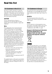
Table of contents Read this first 5 Notes on using your camera 6 Preparation 10 Check the accessories (supplied 10 Insert the batteries 10 Insert a "Memory Stick Duo" (not supplied 12 Getting started 13 Shoot images ... images 18 Printing images 20 Troubleshooting 22 Others 25 Supported Operating Systems for USB connection and application software (supplied 25 Viewing "Cyber-shot Handbook 25 Specifications 26 Identifying parts 27 Indicators on the screen Back cover Enjoying additional functions on recording/playback using the menu Selecting the desired setting Making use...
Table of contents Read this first 5 Notes on using your camera 6 Preparation 10 Check the accessories (supplied 10 Insert the batteries 10 Insert a "Memory Stick Duo" (not supplied 12 Getting started 13 Shoot images ... images 18 Printing images 20 Troubleshooting 22 Others 25 Supported Operating Systems for USB connection and application software (supplied 25 Viewing "Cyber-shot Handbook 25 Specifications 26 Identifying parts 27 Indicators on the screen Back cover Enjoying additional functions on recording/playback using the menu Selecting the desired setting Making use...
Instruction Manual
Page 27
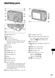
...19) L Tripod receptacle • Use a tripod with a screw length of less than 5.5 mm (7/32 inch), and may damage the camera. You will be unable to firmly secure the camera to shoot still images, see "To shoot an image using the mode dial" (page 16). qj ws qa Others qs qf... qd A Shutter button (15) B Mode dial : To shoot movies : To view or edit images • For details on : v/V/b/B/z Menu off: / / / V Access lamp (12) 27 Identifying parts 1 6 ...
...19) L Tripod receptacle • Use a tripod with a screw length of less than 5.5 mm (7/32 inch), and may damage the camera. You will be unable to firmly secure the camera to shoot still images, see "To shoot an image using the mode dial" (page 16). qj ws qa Others qs qf... qd A Shutter button (15) B Mode dial : To shoot movies : To view or edit images • For details on : v/V/b/B/z Menu off: / / / V Access lamp (12) 27 Identifying parts 1 6 ...
Service Manual
Page 1
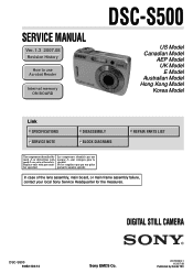
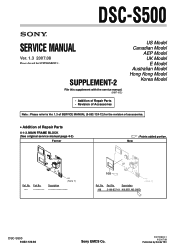
... the measures. Les composants identifiés par une marque 0 sont critiques pour la sécurité. DIGITAL STILL CAMERA DSC-S500 9-852-124-12 Sony EMCS Co. 2007H0800-1 © 2007.08 Published by mark 0 or dotted line with part number specified. In case of the lens assembly, main board, or main frame assembly failure, contact your...
... the measures. Les composants identifiés par une marque 0 sont critiques pour la sécurité. DIGITAL STILL CAMERA DSC-S500 9-852-124-12 Sony EMCS Co. 2007H0800-1 © 2007.08 Published by mark 0 or dotted line with part number specified. In case of the lens assembly, main board, or main frame assembly failure, contact your...
Service Manual
Page 3
...unsoldered or poorly-soldered connections. Look for unauthorized replacement parts, particularly transistors, that no wires are printed with the leadfree mark (LF) indicating the solder contains no lead. (Caution: Some printed circuit boards may DSC-S500 also be set to the customer and recommend their ...etc. • Usable with the same or equivalent type. REPLACE THESE COMPONENTS WITH SONY PARTS WHOSE PART NUMBERS APPEAR AS SHOWN IN THIS MANUAL OR IN SUPPLEMENTS PUBLISHED BY SONY. Ordinary soldering irons can be used but unleaded solder may not come printed with ...
...unsoldered or poorly-soldered connections. Look for unauthorized replacement parts, particularly transistors, that no wires are printed with the leadfree mark (LF) indicating the solder contains no lead. (Caution: Some printed circuit boards may DSC-S500 also be set to the customer and recommend their ...etc. • Usable with the same or equivalent type. REPLACE THESE COMPONENTS WITH SONY PARTS WHOSE PART NUMBERS APPEAR AS SHOWN IN THIS MANUAL OR IN SUPPLEMENTS PUBLISHED BY SONY. Ordinary soldering irons can be used but unleaded solder may not come printed with ...
Service Manual
Page 4
DISASSEMBLY 2-1. Front Block 4-2 4-1-3. Overall Section 4-1 4-1-2. SERVICE NOTE 1-1. Process After Fixing Flash Error 1-1 1-2. Disassembly 2-1 3. Power Block Diagram 3-2 4. Method for Copying or Erasing the Data in Internal Memory 1-1 2. Accessories 4-4 DSC-S500 - 4 - Overall Block Diagram 3-1 3-2. Section TABLE OF CONTENTS Title Page 1. BLOCK DIAGRAMS 3-1. REPAIR PARTS LIST 4-1. Exploded Views 4-1 4-1-1. Main Frame Block 4-3 4-2.
DISASSEMBLY 2-1. Front Block 4-2 4-1-3. Overall Section 4-1 4-1-2. SERVICE NOTE 1-1. Process After Fixing Flash Error 1-1 1-2. Disassembly 2-1 3. Power Block Diagram 3-2 4. Method for Copying or Erasing the Data in Internal Memory 1-1 2. Accessories 4-4 DSC-S500 - 4 - Overall Block Diagram 3-1 3-2. Section TABLE OF CONTENTS Title Page 1. BLOCK DIAGRAMS 3-1. REPAIR PARTS LIST 4-1. Exploded Views 4-1 4-1-1. Main Frame Block 4-3 4-2.

Service Manual
Page 10
REPAIR PARTS LIST 2 1 1 7 8 9 1 1 1 4 3 Main Frame Block (See page 4-3.) 6 1 Front Block (See page 4-2.) 5 1 Ref. Description 2-699-483-01 LID, Battery Case 2-682-974-01 Mode Dial 2-682-975-01 Shutter Button 2-682-976-01 Shutter Button Spring DSC-S500 4-1 EXPLODED VIEWS 4-1-1. No. 6 7 8 9 Part No. 4-1. No. 1 2 3 4 5 Part No. OVERALL SECTION 4. Description 2-682-984-01 Screw TP1.7*3.5 X-2149-431-1 Cover Assy, Rear X-2149-248-1 Belt (left), Inner X-2109-765-1 Middle Cover Assy (right) 2-694-421-01 Screw TP1.7*16 Ref.
REPAIR PARTS LIST 2 1 1 7 8 9 1 1 1 4 3 Main Frame Block (See page 4-3.) 6 1 Front Block (See page 4-2.) 5 1 Ref. Description 2-699-483-01 LID, Battery Case 2-682-974-01 Mode Dial 2-682-975-01 Shutter Button 2-682-976-01 Shutter Button Spring DSC-S500 4-1 EXPLODED VIEWS 4-1-1. No. 6 7 8 9 Part No. 4-1. No. 1 2 3 4 5 Part No. OVERALL SECTION 4. Description 2-682-984-01 Screw TP1.7*3.5 X-2149-431-1 Cover Assy, Rear X-2149-248-1 Belt (left), Inner X-2109-765-1 Middle Cover Assy (right) 2-694-421-01 Screw TP1.7*16 Ref.
Service Manual
Page 12
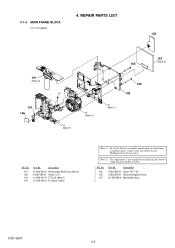
... of the lens assembly, main board, or main frame assembly failure, contact your local Sony Service Headquarter for the measures. (Note 2) The adjustment is not required after replacing the stroboscope block assembly or LCD. REPAIR PARTS LIST 4-1-3. 4. MAIN FRAME BLOCK ns: not supplied 104 101 (Note 2) 107 106... 103 (Note 2) 105 ns ns (Note 1) ns (Note 1) 105 102 ns (Note 1) Ref. No. 101 102 103 104 Part No. Ref. No. 105 106 107 Part No. Description 2-682-983-01 Screw TP1.7*20 2-682-993-01 Sheet, Microphone Fixed A-1188-556-A Microphone Assy DSC-S500 4-3
... of the lens assembly, main board, or main frame assembly failure, contact your local Sony Service Headquarter for the measures. (Note 2) The adjustment is not required after replacing the stroboscope block assembly or LCD. REPAIR PARTS LIST 4-1-3. 4. MAIN FRAME BLOCK ns: not supplied 104 101 (Note 2) 107 106... 103 (Note 2) 105 ns ns (Note 1) ns (Note 1) 105 102 ns (Note 1) Ref. No. 101 102 103 104 Part No. Ref. No. 105 106 107 Part No. Description 2-682-983-01 Screw TP1.7*20 2-682-993-01 Sheet, Microphone Fixed A-1188-556-A Microphone Assy DSC-S500 4-3
Service Manual
Page 13
... (size AA) Alkaline Battery (Note) Preparation Digital Still Camera Instruction Manual DSC-S500 Before operating the unit, please read this product and answers to these numbers whenever you call upon your TV Troubleshooting Others Index 2-689-526-11(1) Cyber-shot Handbook (not supplied with the unit as a service part. Model No. Ownerís Record The model and...
... (size AA) Alkaline Battery (Note) Preparation Digital Still Camera Instruction Manual DSC-S500 Before operating the unit, please read this product and answers to these numbers whenever you call upon your TV Troubleshooting Others Index 2-689-526-11(1) Cyber-shot Handbook (not supplied with the unit as a service part. Model No. Ownerís Record The model and...
Service Manual
Page 16
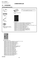
No. SUPPLEMENT-2 File this supplement with the service manual. (DI07-052) • Addition of Repair Parts • Revision of Accessories US Model Canadian Model AEP Model UK Model E Model Australian Model Hong Kong Model Korea Model Note : Please ...manual page 4-3) Former & : Points added portion. New Ref. Description 3-100-837-01 HOLDER, MS CARD ) ns (Note 1) DSC-S500 9-852-124-82 Sony EMCS Co. 2007H0800-1 © 2007.08 Published by Kohda TEC Part No ns (Note 1) Description 108 Ref. DSC-S500 SERVICE MANUAL Ver. 1.3 2007.08 Please discard the SUPPLEMENT-1. No. 108...
No. SUPPLEMENT-2 File this supplement with the service manual. (DI07-052) • Addition of Repair Parts • Revision of Accessories US Model Canadian Model AEP Model UK Model E Model Australian Model Hong Kong Model Korea Model Note : Please ...manual page 4-3) Former & : Points added portion. New Ref. Description 3-100-837-01 HOLDER, MS CARD ) ns (Note 1) DSC-S500 9-852-124-82 Sony EMCS Co. 2007H0800-1 © 2007.08 Published by Kohda TEC Part No ns (Note 1) Description 108 Ref. DSC-S500 SERVICE MANUAL Ver. 1.3 2007.08 Please discard the SUPPLEMENT-1. No. 108...

Service Manual
Page 17
... character strings displayed next. (Character strings entered previously are in the text box.) Application to the Service Manual: The parts on the drawing pages (block diagrams, circuit diagrams, printed circuit boards) and parts list pages in the zoom control box to the next page, click the . Place the pointer in the position...
... character strings displayed next. (Character strings entered previously are in the text box.) Application to the Service Manual: The parts on the drawing pages (block diagrams, circuit diagrams, printed circuit boards) and parts list pages in the zoom control box to the next page, click the . Place the pointer in the position...
Service Manual
Page 18
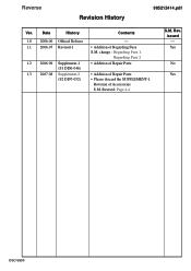
Revised: Page 4-4 S.M. Rev. issued - Revision of Repair Parts (S2 DI07-052) • Please discard the SUPPLEMENT-1. Yes No Yes DSC-S500 Reverse Revision History 985212414.pdf Ver. change : Regarding Fuse 1, Regarding Fuse 2 1.2 2006.09 Supplement-1 • Addition of Repair Parts (S1 DI06-046) 1.3 2007.08 Supplement-2 • Addition of Accessories S.M. Date History Contents 1.0 2006.06 Official Release - 1.1 2006.07 Revised-1 • Addition of Regarding Fuse S.M.
Revised: Page 4-4 S.M. Rev. issued - Revision of Repair Parts (S2 DI07-052) • Please discard the SUPPLEMENT-1. Yes No Yes DSC-S500 Reverse Revision History 985212414.pdf Ver. change : Regarding Fuse 1, Regarding Fuse 2 1.2 2006.09 Supplement-1 • Addition of Repair Parts (S1 DI06-046) 1.3 2007.08 Supplement-2 • Addition of Accessories S.M. Date History Contents 1.0 2006.06 Official Release - 1.1 2006.07 Revised-1 • Addition of Regarding Fuse S.M.


