Service Manual
Page 7
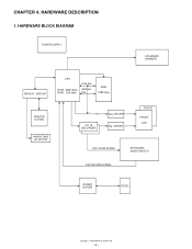
DRIVER Dig. HARDWARE BLOCK DIAGRAM POWER SUPPLY STANDARD DRAWER. DRIVER , SENSOR CPU ROM : 256K Byte RAM : 20K Byte Data bus Address bus RAM 128K Byte PRINTER M-T53II PAPER TAKE UP MOTOR 4 to 16 DECORDER Seg. DRIVER POPUP FRONT LED KEY SCAN SIGNAL KEYBOARD MODE SWITCH KEY RETURN SIGNAL RS232C DRIVER RS232 XE-A202U HARDWARE DESCRIPTION - 6 - CHAPTER 4. HARDWARE DESCRIPTION 1.
DRIVER Dig. HARDWARE BLOCK DIAGRAM POWER SUPPLY STANDARD DRAWER. DRIVER , SENSOR CPU ROM : 256K Byte RAM : 20K Byte Data bus Address bus RAM 128K Byte PRINTER M-T53II PAPER TAKE UP MOTOR 4 to 16 DECORDER Seg. DRIVER POPUP FRONT LED KEY SCAN SIGNAL KEYBOARD MODE SWITCH KEY RETURN SIGNAL RS232C DRIVER RS232 XE-A202U HARDWARE DESCRIPTION - 6 - CHAPTER 4. HARDWARE DESCRIPTION 1.
Service Manual
Page 10
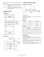
... driven to LOW by the comparator IC4B. 6. CPU port 76 P14 75 P15 74 P16 73 P17 Signal used IN1 IN2 ENA1 ENA2 Drive step Driver IC input (CPU output) Motor drive signal STEP IN1 IN2 ENA1 ENA2 A B /A /B (OUT1) (OUT3) (OUT2) (OUT4) 1 LL H H H H ...H 4 LH H H H L L H 2) Print circuit Thermal head configuration As shown in the equivalent circuit in the latch register by two comparators and sent to the print data. XE-A202U HARDWARE DESCRIPTION - 9 - The head conduction signals (print commands 1 ~ 6) turn the gate on to conduct the heating ...
... driven to LOW by the comparator IC4B. 6. CPU port 76 P14 75 P15 74 P16 73 P17 Signal used IN1 IN2 ENA1 ENA2 Drive step Driver IC input (CPU output) Motor drive signal STEP IN1 IN2 ENA1 ENA2 A B /A /B (OUT1) (OUT3) (OUT2) (OUT4) 1 LL H H H H ...H 4 LH H H H L L H 2) Print circuit Thermal head configuration As shown in the equivalent circuit in the latch register by two comparators and sent to the print data. XE-A202U HARDWARE DESCRIPTION - 9 - The head conduction signals (print commands 1 ~ 6) turn the gate on to conduct the heating ...


