
Operation Manual
Page 1
OPERATION MANUAL MODEL PG-B10S LCD PROJECTOR Introduction Basic Operation Projection Functions Using the Menu Connections Screen Setup Appendix
OPERATION MANUAL MODEL PG-B10S LCD PROJECTOR Introduction Basic Operation Projection Functions Using the Menu Connections Screen Setup Appendix
Operation Manual
Page 2
.../EEC och 73/23/EEC så som kompletteras av 93/68/ EEC. IMPORTANT For your assistance in reporting the loss or theft of your Projector, please record the Serial Number located on muutettu direktiivillä 93/68/EEC. Este equipamento obedece às exigências das directivas 89/336...contents of the carton thoroughly against the list of Directives 89/336/EEC and 73/23/EEC as amended by 93/68/ EEC. Model No.: PG-B10S Serial No.: This equipment complies with the requirements of "Supplied accessories" on page 9. Dieses Gerät entspricht den Anforderungen der EG-Richtlinien 89/...
.../EEC och 73/23/EEC så som kompletteras av 93/68/ EEC. IMPORTANT For your assistance in reporting the loss or theft of your Projector, please record the Serial Number located on muutettu direktiivillä 93/68/EEC. Este equipamento obedece às exigências das directivas 89/336...contents of the carton thoroughly against the list of Directives 89/336/EEC and 73/23/EEC as amended by 93/68/ EEC. Model No.: PG-B10S Serial No.: This equipment complies with the requirements of "Supplied accessories" on page 9. Dieses Gerät entspricht den Anforderungen der EG-Richtlinien 89/...
Operation Manual
Page 5
... notification of inspection, modification, or recall that you immediately receive the full benefit of the parts, service and labor warranty applicable to your new SHARP Projector, using the projector, please read this equipment in a residential area is intended to alert the user to the presence of uninsulated "dangerous voltage" within a triangle is operated...
... notification of inspection, modification, or recall that you immediately receive the full benefit of the parts, service and labor warranty applicable to your new SHARP Projector, using the projector, please read this equipment in a residential area is intended to alert the user to the presence of uninsulated "dangerous voltage" within a triangle is operated...
Operation Manual
Page 6
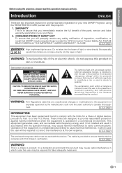
... RADIATION : CAN CAUSE EYE DAMAGE. PRECAUTIONS A OBSERVER LORS DU REMPLACEMENT DE LA LAMPE. This SHARP projector uses an LCD (Liquid Crystal Display) panel. HOT SURFACE INSIDE. During normal operation, when putting the projector into the standby mode always use the STANDBY button on the projector or on page 65. DURING NORMAL OPERATION, NEVER TURN THE...
... RADIATION : CAN CAUSE EYE DAMAGE. PRECAUTIONS A OBSERVER LORS DU REMPLACEMENT DE LA LAMPE. This SHARP projector uses an LCD (Liquid Crystal Display) panel. HOT SURFACE INSIDE. During normal operation, when putting the projector into the standby mode always use the STANDBY button on the projector or on page 65. DURING NORMAL OPERATION, NEVER TURN THE...
Operation Manual
Page 7
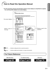
... menu screen for INPUT 1 (RGB) mode Button used in an adjustment menu. • This operation can be performed by using the projector. Menu icon Menu screen Picture Fine Sync Options Language PRJ Mode Note • The "Fine Sync" menu is not available for the selected...Buttons used in this step Menu Selections (Adjustments) • The following procedure is selected. 2 Press \ or | to adjust the image and various projector settings. For Future Reference Maintenance Page 60 Troubleshooting Pages 71 and 72 Glossary Page 76 -3 Note • The on-screen display shown on the ...
... menu screen for INPUT 1 (RGB) mode Button used in an adjustment menu. • This operation can be performed by using the projector. Menu icon Menu screen Picture Fine Sync Options Language PRJ Mode Note • The "Fine Sync" menu is not available for the selected...Buttons used in this step Menu Selections (Adjustments) • The following procedure is selected. 2 Press \ or | to adjust the image and various projector settings. For Future Reference Maintenance Page 60 Troubleshooting Pages 71 and 72 Glossary Page 76 -3 Note • The on-screen display shown on the ...
Operation Manual
Page 8
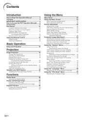
...the Remote Control 15 Usable Range 15 Inserting the Batteries 15 Basic Operation Setup and Projection 16 Projection Image Projection 18 Turning the Projector on 18 Switching the INPUT Mode 19 Adjusting the Volume 19 Displaying the Black Screen and Turning off the Sound Temporarily 20 ...Correcting Trapezoidal Distortion 20 Turning the Power off (Putting the Projector into the Standby Mode) .... 21 Adjusting the Lens 22 Using the Adjustment Feet 23 Variable Lens Shift Feature 24 Adjusting the Projected...
...the Remote Control 15 Usable Range 15 Inserting the Batteries 15 Basic Operation Setup and Projection 16 Projection Image Projection 18 Turning the Projector on 18 Switching the INPUT Mode 19 Adjusting the Volume 19 Displaying the Black Screen and Turning off the Sound Temporarily 20 ...Correcting Trapezoidal Distortion 20 Turning the Power off (Putting the Projector into the Standby Mode) .... 21 Adjusting the Lens 22 Using the Adjustment Feet 23 Variable Lens Shift Feature 24 Adjusting the Projected...
Operation Manual
Page 9
... Screen Setup Setting up the Screen 56 Screen Size and Projection Distance 57 Projecting a Revered Image 58 Appendix Carrying the Projector 59 How to Use the Carrying Case 59 Maintenance 60 Replacing the Air Filter 61 Cleaning and Replacing the Air Filter 61 Maintenance Indicators 63 ... Unit 66 Resetting the Lamp Timer 67 Connecting Pin Assignments 68 RS-232C Specifications and Command Settings 69 Computer Compatibility Chart 70 Troubleshooting 71 For SHARP Assistance 73 Specifications 74 Dimensions 75 Glossary 76 Index 77 -5
... Screen Setup Setting up the Screen 56 Screen Size and Projection Distance 57 Projecting a Revered Image 58 Appendix Carrying the Projector 59 How to Use the Carrying Case 59 Maintenance 60 Replacing the Air Filter 61 Cleaning and Replacing the Air Filter 61 Maintenance Indicators 63 ... Unit 66 Resetting the Lamp Timer 67 Connecting Pin Assignments 68 RS-232C Specifications and Command Settings 69 Computer Compatibility Chart 70 Troubleshooting 71 For SHARP Assistance 73 Specifications 74 Dimensions 75 Glossary 76 Index 77 -5
Operation Manual
Page 11
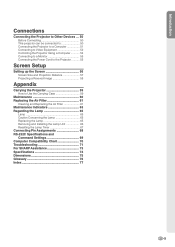
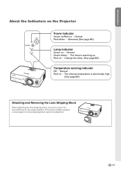
...be safely tilted to a maximum angle of 12 degrees. Caution concerning the lamp unit I Do not carry the projector by a Sharp Authorized Projector Dealer or Service Center. ity, SHARP recommends that it is from -4°F to 140°F (-20°C to +60°C). Internal cleaning ...equipment to hard impact and/ or vibration. Temperature monitor function I Please read the following safeguards when setting up your nearest Sharp Authorized Projector Dealer or Service Center for the country you are in damage. Info • The cooling fan regulates the internal temperature,...
...be safely tilted to a maximum angle of 12 degrees. Caution concerning the lamp unit I Do not carry the projector by a Sharp Authorized Projector Dealer or Service Center. ity, SHARP recommends that it is from -4°F to 140°F (-20°C to +60°C). Internal cleaning ...equipment to hard impact and/ or vibration. Temperature monitor function I Please read the following safeguards when setting up your nearest Sharp Authorized Projector Dealer or Service Center for the country you are in damage. Info • The cooling fan regulates the internal temperature,...
Operation Manual
Page 12
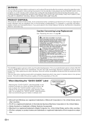
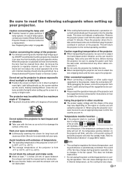
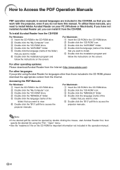
For other languages: If you want to view. 5 Double click the "B10" pdf file to access the projector manuals. Accessing the PDF Manuals For Windows: 1 Insert the CD-ROM in the CD-ROM drive. 2 Double click the "My Computer" icon. 3 Double click the "..." drive. 4 Double click the "MANUALS" folder. 5 Double click the language (name of the folder) that you want to view. 6 Double click the "B10" pdf file to access the projector manuals. For Macintosh: 1 Insert the CD-ROM in the CD-ROM drive. 2 Double click the "CD-ROM" icon. 3 Double click the "ACROBAT" folder...
For other languages: If you want to view. 5 Double click the "B10" pdf file to access the projector manuals. Accessing the PDF Manuals For Windows: 1 Insert the CD-ROM in the CD-ROM drive. 2 Double click the "My Computer" icon. 3 Double click the "..." drive. 4 Double click the "MANUALS" folder. 5 Double click the language (name of the folder) that you want to view. 6 Double click the "B10" pdf file to access the projector manuals. For Macintosh: 1 Insert the CD-ROM in the CD-ROM drive. 2 Double click the "CD-ROM" icon. 3 Double click the "ACROBAT" folder...
Operation Manual
Page 13
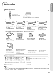
...)) I RS-232C serial control cable (32'10" (10.0 m)) I 5 BNC to the wall outlet in your nearest Sharp Authorized Projector Dealer or Service Center. -9 For Australia, New Zealand and Oceania (6' (1.8 m)) QACCLA005WJPZ RGB cable (9'10" (3.0 m)) QCNWGA012WJPZ... Carrying case GCASNA009WJSA Lens cap (attached) CCAPHA004WJ01 Extra air filter PFILDA010WJZZ Lens shipping block (attached) SPAKXA333WJZZ Projector manual and technical reference CD-ROM UDSKAA039WJZZ "QUICK GUIDE" label TLABZA439WJZZ Operation manual (this manual) Optional accessories I 3 RCA to...
...)) I RS-232C serial control cable (32'10" (10.0 m)) I 5 BNC to the wall outlet in your nearest Sharp Authorized Projector Dealer or Service Center. -9 For Australia, New Zealand and Oceania (6' (1.8 m)) QACCLA005WJPZ RGB cable (9'10" (3.0 m)) QCNWGA012WJPZ... Carrying case GCASNA009WJSA Lens cap (attached) CCAPHA004WJ01 Extra air filter PFILDA010WJZZ Lens shipping block (attached) SPAKXA333WJZZ Projector manual and technical reference CD-ROM UDSKAA039WJZZ "QUICK GUIDE" label TLABZA439WJZZ Operation manual (this manual) Optional accessories I 3 RCA to...

Operation Manual
Page 14
... the standby mode. Remote control 15 sensor Zoom knob 22 Front adjustment foot 23 (on the bottom of the projector) HEIGHT ADJUST button 23 Attaching and removing the lens cap • Press on the two buttons of the lens cap and remove it from the ... MENU button For displaying adjustment and setting screens. Part Names Numbers in refer to lock it in this operation manual where the topic is explained. Projector (Front and Top View) ON button 18 For turning the power on.
... the standby mode. Remote control 15 sensor Zoom knob 22 Front adjustment foot 23 (on the bottom of the projector) HEIGHT ADJUST button 23 Attaching and removing the lens cap • Press on the two buttons of the lens cap and remove it from the ... MENU button For displaying adjustment and setting screens. Part Names Numbers in refer to lock it in this operation manual where the topic is explained. Projector (Front and Top View) ON button 18 For turning the power on.
Operation Manual
Page 15
Normal Green blinks ... Change the lamp. (See page 63.) Temperature warning indicator Off ... Introduction About the Indicators on the Projector Power indicator Green on/Red on ... Normal Red blinks ... Abnormal (See page 63.) Lamp indicator Green on ... Normal Red on ... The internal temperature is shifted ...
Normal Green blinks ... Change the lamp. (See page 63.) Temperature warning indicator Off ... Introduction About the Indicators on the Projector Power indicator Green on/Red on ... Normal Red blinks ... Abnormal (See page 63.) Lamp indicator Green on ... Normal Red on ... The internal temperature is shifted ...

Operation Manual
Page 16
... a Kensington Security Standard connector for computer RGB and component signals. Part Names Numbers in refer to secure the projector. -12 Refer to use with an S-video terminal. 52 INPUT 3 terminal Terminal for connecting video equipment. 51 AUDIO INPUT terminal Shared ...3. Kensington Security Standard connector 60 Exhaust vent 23 Rear adjustment foot (on how to the information that came with the system for connecting a monitor. Projector (Rear View) INPUT 1 terminal 51 Terminal for use it to the main pages in this operation manual where the topic is explained. RS-232C ...
... a Kensington Security Standard connector for computer RGB and component signals. Part Names Numbers in refer to secure the projector. -12 Refer to use with an S-video terminal. 52 INPUT 3 terminal Terminal for connecting video equipment. 51 AUDIO INPUT terminal Shared ...3. Kensington Security Standard connector 60 Exhaust vent 23 Rear adjustment foot (on how to the information that came with the system for connecting a monitor. Projector (Rear View) INPUT 1 terminal 51 Terminal for use it to the main pages in this operation manual where the topic is explained. RS-232C ...

Operation Manual
Page 17
Introduction INPUT/OUTPUT Terminals and Connectable Main Equipment RS-232C terminal Connecting the computer to control the projector. (See page 54.) INPUT 1 terminal Connecting the computer. (See page 51.) Connecting video equipment with component output terminal (DVD player, DTV decoder, etc.). (See page ...
Introduction INPUT/OUTPUT Terminals and Connectable Main Equipment RS-232C terminal Connecting the computer to control the projector. (See page 54.) INPUT 1 terminal Connecting the computer. (See page 51.) Connecting video equipment with component output terminal (DVD player, DTV decoder, etc.). (See page ...

Operation Manual
Page 18
... speaker sound level. -14 UNDO button 21 For undoing an operation or returning to a computer. Remote Control (Front View) STANDBY button 21 For putting the projector into the standby mode. ENLARGE (Enlarge/Reduce) 28 buttons For enlarging or reducing part of the image. Part Names Numbers in refer to the main...
... speaker sound level. -14 UNDO button 21 For undoing an operation or returning to a computer. Remote Control (Front View) STANDBY button 21 For putting the projector into the standby mode. ENLARGE (Enlarge/Reduce) 28 buttons For enlarging or reducing part of the image. Part Names Numbers in refer to the main...

Operation Manual
Page 19
... and marks inside the battery compartment. • Batteries of the batteries may run out, as possible with this case, move the projector away from the remote control if you will not be re- This may malfunction under a fluorescent lamp. Introduction Using the Remote Control...sure the polarities correctly match the and marks inside the battery compartment. 3 Attach the cover and slide it clicks into place. In this projector may cause them using a cloth. • The batteries included with new batteries. • Remove the batteries from the fluorescent lamp. Please...
... and marks inside the battery compartment. • Batteries of the batteries may run out, as possible with this case, move the projector away from the remote control if you will not be re- This may malfunction under a fluorescent lamp. Introduction Using the Remote Control...sure the polarities correctly match the and marks inside the battery compartment. 3 Attach the cover and slide it clicks into place. In this projector may cause them using a cloth. • The batteries included with new batteries. • Remove the batteries from the fluorescent lamp. Please...

Operation Manual
Page 20
... the computer and plug the power cord into the AC socket of the projector and the computer is explained as an example. 3 ON button 5 INPUT button 4 KEYSTONE button 4 Adjustment buttons ('"\ |) 3 ON button 4 KEYSTONE button 4 Zoom knob 4 Focus ring 4 Adjustment ...buttons ('"\ |) 5 INPUT 1 button 4 Lens shift lever 4 HEIGHT ADJUST button 1. Setup and Projection In this section, connection of the projector When connecting equipment other than the computer, see pages 13 and 50. Pages 51, 55 3.
... the computer and plug the power cord into the AC socket of the projector and the computer is explained as an example. 3 ON button 5 INPUT button 4 KEYSTONE button 4 Adjustment buttons ('"\ |) 3 ON button 4 KEYSTONE button 4 Zoom knob 4 Focus ring 4 Adjustment ...buttons ('"\ |) 5 INPUT 1 button 4 Lens shift lever 4 HEIGHT ADJUST button 1. Setup and Projection In this section, connection of the projector When connecting equipment other than the computer, see pages 13 and 50. Pages 51, 55 3.

Operation Manual
Page 21
...On-screen display (RGB) On-screen display (Component) • When pressing on the remote control. Angle • Adjust the projector angle using the zoom knob. On the remote control Page 20 5. Page 22 Page 25 3 Correct trapezoidal distortion Correcting trapezoidal distortion ... INPUT mode Select the "INPUT 1" using the INPUT button on the projector or the INPUT 1 button on the projector, input mode switches in zoom out Page 22 2 Adjust the projected image position and the projector angle Projection position • Adjust the projected image position using the Keystone...
...On-screen display (RGB) On-screen display (Component) • When pressing on the remote control. Angle • Adjust the projector angle using the zoom knob. On the remote control Page 20 5. Page 22 Page 25 3 Correct trapezoidal distortion Correcting trapezoidal distortion ... INPUT mode Select the "INPUT 1" using the INPUT button on the projector or the INPUT 1 button on the projector, input mode switches in zoom out Page 22 2 Adjust the projected image position and the projector angle Projection position • Adjust the projected image position using the Keystone...

Operation Manual
Page 22
...standby mode and immediately turned on the remote control. • The power indicator illuminates green. • After the lamp indicator illuminates, the projector is set, the keycode input box will appear. MKeycode input box ON button -18 If you want to change the on-screen display ...the keycode. Power indicator ON button Lamp indicator Note • The lamp indicator illuminates, indicating the status of the lamp. Image Projection Turning the Projector on page 24. For details about the Anti-Theft function, refer to "Anti-Theft (Setting the AntiTheft)" on page 46. • When ...
...standby mode and immediately turned on the remote control. • The power indicator illuminates green. • After the lamp indicator illuminates, the projector is set, the keycode input box will appear. MKeycode input box ON button -18 If you want to change the on-screen display ...the keycode. Power indicator ON button Lamp indicator Note • The lamp indicator illuminates, indicating the status of the lamp. Image Projection Turning the Projector on page 24. For details about the Anti-Theft function, refer to "Anti-Theft (Setting the AntiTheft)" on page 46. • When ...

Operation Manual
Page 23
... lower the volume. will be displayed. INPUT 2 Used for the connected equipment. Note • Pressing will raise the volume. • On the projector, the volume can be displayed. • The INPUT mode is set to "OFF". (See page 41.) About the INPUT mode INPUT 1 Used for... 1 mode Using RGB Using Component INPUT 2 mode Using S-Video INPUT 3 mode Using Video ➝ ➝ ➝ Adjusting the Volume Press or on the projector, input mode switches in order of the "Options" menu is not displayed when "OSD Display" of INPUT 1 INPUT 2 INPUT 3 . nected to receive is ...
... lower the volume. will be displayed. INPUT 2 Used for the connected equipment. Note • Pressing will raise the volume. • On the projector, the volume can be displayed. • The INPUT mode is set to "OFF". (See page 41.) About the INPUT mode INPUT 1 Used for... 1 mode Using RGB Using Component INPUT 2 mode Using S-Video INPUT 3 mode Using Video ➝ ➝ ➝ Adjusting the Volume Press or on the projector, input mode switches in order of the "Options" menu is not displayed when "OSD Display" of INPUT 1 INPUT 2 INPUT 3 . nected to receive is ...


