

User Manual
Page 3
...PPM42S3Q model uses the same MDC program CD used for PPM42S3 model. The PPM50H3Q/63H3Q models use the same MDC program CD used for PPM50H3/63H3 models. 3 This image retention is not covered by image retention. - Warranty does not cover any damage caused by the warranty. ... still image. ◆ Cell Defect The plasma display panel consists of fine cells. Checking Parts PPM42S3Q & PPM50H3Q Owner's Instructions Remote Control/ AAA Batteries Power Cord Speaker Wires (2EA) Stand-Base (2EA) 2 Install CD - Burn-in height and do not produce light or remain lit. ◆ Height...
...PPM42S3Q model uses the same MDC program CD used for PPM42S3 model. The PPM50H3Q/63H3Q models use the same MDC program CD used for PPM50H3/63H3 models. 3 This image retention is not covered by image retention. - Warranty does not cover any damage caused by the warranty. ... still image. ◆ Cell Defect The plasma display panel consists of fine cells. Checking Parts PPM42S3Q & PPM50H3Q Owner's Instructions Remote Control/ AAA Batteries Power Cord Speaker Wires (2EA) Stand-Base (2EA) 2 Install CD - Burn-in height and do not produce light or remain lit. ◆ Height...
User Manual
Page 5
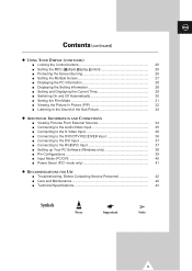
... the RGB(PC) Input 37 ■ Setting up Your PC Software (Windows only 38 ■ Pin Configurations 39 ■ Input Mode (PC/DVI 40 ■ Power Saver (PC1 mode only 41 ◆ RECOMMENDATIONS FOR USE ■ Troubleshooting: Before Contacting Service Personnel 42 ■ Care and Maintenance 42 ■ Technical Specifications 43...
... the RGB(PC) Input 37 ■ Setting up Your PC Software (Windows only 38 ■ Pin Configurations 39 ■ Input Mode (PC/DVI 40 ■ Power Saver (PC1 mode only 41 ◆ RECOMMENDATIONS FOR USE ■ Troubleshooting: Before Contacting Service Personnel 42 ■ Care and Maintenance 42 ■ Technical Specifications 43...
User Manual
Page 6
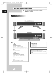
... - VOL + - Store your settings in the menu. Volume adjustment. - Adjust an option value respectively. (VOL + : Enter to turn the PDP on your model. Power Off; Green c Remote Control Signal Receiver Aim the remote control towards this spot on screen, the Main menu is displayed on the PDP.... 6 b Power Indicator - BN68-00654A-01Eng 4/19/04 4:12 PM Page 6 Your New Plasma Display Panel ➢ The actual configuration on your PDP may ...
... - VOL + - Store your settings in the menu. Volume adjustment. - Adjust an option value respectively. (VOL + : Enter to turn the PDP on your model. Power Off; Green c Remote Control Signal Receiver Aim the remote control towards this spot on screen, the Main menu is displayed on the PDP.... 6 b Power Indicator - BN68-00654A-01Eng 4/19/04 4:12 PM Page 6 Your New Plasma Display Panel ➢ The actual configuration on your PDP may ...
User Manual
Page 7
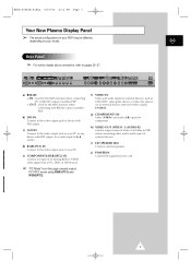
.... f) VIDEO IN Video and audio inputs for external devices, such as VCR, DVD, video game device or video disc players (or for component. j) POWER IN Connect the supplied power cord. 7 e) COMPONENT2/RGB2(PC2) IN Connect for device with DVI output. (It is audio input for the MDC function when connecting PC or...
.... f) VIDEO IN Video and audio inputs for external devices, such as VCR, DVD, video game device or video disc players (or for component. j) POWER IN Connect the supplied power cord. 7 e) COMPONENT2/RGB2(PC2) IN Connect for device with DVI output. (It is audio input for the MDC function when connecting PC or...
User Manual
Page 14
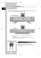
... PM Page 14 Connecting Speakers (continued) ENG Connect the speaker audio cable to secure it. PPM42S3Q/PPM50H3Q PPM63H3Q ➢ ◆ The speakers MUST have to a power handling capability of 10 watts minimum (impedance 8Ω). ◆ When you connect the speaker wire to the external speaker out connector, first bind the speaker...
... PM Page 14 Connecting Speakers (continued) ENG Connect the speaker audio cable to secure it. PPM42S3Q/PPM50H3Q PPM63H3Q ➢ ◆ The speakers MUST have to a power handling capability of 10 watts minimum (impedance 8Ω). ◆ When you connect the speaker wire to the external speaker out connector, first bind the speaker...

User Manual
Page 22
... √ œ Off √ œ Off √ œ Off √ Move Sel. Return 1 Press the MENU button. Once the Pseudo stereo or Virtual surround is powered on or off. ◆ Pseudo Stereo / Virtual Surround Pseudo stereo feature converts a monaural sound signal into two identical left and right channels. Result: The main...
... √ œ Off √ œ Off √ œ Off √ Move Sel. Return 1 Press the MENU button. Once the Pseudo stereo or Virtual surround is powered on or off. ◆ Pseudo Stereo / Virtual Surround Pseudo stereo feature converts a monaural sound signal into two identical left and right channels. Result: The main...

User Manual
Page 30
... your PDP left on for tuning to the volume of your choice at the time you select 1 Press the MENU button. button to ➣ Absent Power Off Your PDP will not work when the "Off Time" is displayed. 2 Press the ▲ or ▼ button to be switched on . 7 Press the ▲...
... your PDP left on for tuning to the volume of your choice at the time you select 1 Press the MENU button. button to ➣ Absent Power Off Your PDP will not work when the "Off Time" is displayed. 2 Press the ▲ or ▼ button to be switched on . 7 Press the ▲...
User Manual
Page 39
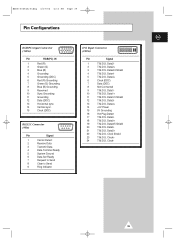
... T.M.D.S. Data3- 13 T.M.D.S. Clock+ 24 T.M.D.S. Data1/3 Shield 12 T.M.D.S. Data5+ 22 T.M.D.S. Clock Shield 23 T.M.D.S. Data2- 2 T.M.D.S. Data0+ 19 T.M.D.S. Data5- 21 T.M.D.S. Data0- 18 T.M.D.S. Clock- 39 Data4- 5 T.M.D.S. Data3+ 14 +5V Power 15 5V Grounding 16 Hot Plug Detect 17 T.M.D.S. Data0/5 Shield 20 T.M.D.S. Data1+ 11 T.M.D.S. BN68-00654A-01Eng 4/19/04 4:13 PM Page 39 Pin Configurations ENG...
... T.M.D.S. Data3- 13 T.M.D.S. Clock+ 24 T.M.D.S. Data1/3 Shield 12 T.M.D.S. Data5+ 22 T.M.D.S. Clock Shield 23 T.M.D.S. Data2- 2 T.M.D.S. Data0+ 19 T.M.D.S. Data5- 21 T.M.D.S. Data0- 18 T.M.D.S. Clock- 39 Data4- 5 T.M.D.S. Data3+ 14 +5V Power 15 5V Grounding 16 Hot Plug Detect 17 T.M.D.S. Data0/5 Shield 20 T.M.D.S. Data1+ 11 T.M.D.S. BN68-00654A-01Eng 4/19/04 4:13 PM Page 39 Pin Configurations ENG...

User Manual
Page 41
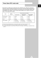
...for a certain amount of time. State Horizontal Sync Vertical Sync Video Power Indicator Normal Operation Active Active Active Off Power-saving Function Mode Standby Mode Inactive Suspend Mode Position A1 Active Power-off Mode Position A2 Inactive Active Inactive Inactive Blanked Blanked Blanked Red ...) (1 sec Interval) ◆ This monitor automatically returns to set up this feature. BN68-00654A-01Eng 4/19/04 4:13 PM Page 41 Power Saver (PC1 mode only) ENG This monitor has a built-in your computer to normal operation when horizontal and vertical sync return. ◆ ...
...for a certain amount of time. State Horizontal Sync Vertical Sync Video Power Indicator Normal Operation Active Active Active Off Power-saving Function Mode Standby Mode Inactive Suspend Mode Position A1 Active Power-off Mode Position A2 Inactive Active Inactive Inactive Blanked Blanked Blanked Red ...) (1 sec Interval) ◆ This monitor automatically returns to set up this feature. BN68-00654A-01Eng 4/19/04 4:13 PM Page 41 Power Saver (PC1 mode only) ENG This monitor has a built-in your computer to normal operation when horizontal and vertical sync return. ◆ ...
User Manual
Page 42
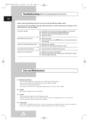
... black and white picture Sound and picture interference Remote control malfunctions ◆ Check that the mains lead has been connected to a warm place, unplug the power cord for at least two hours so that moisture that may have pressed the ON or OFF button. ◆ Check the picture contrast and brightness... PDP. ◆ Cabinet - Keep the ventilation openings clear. - BN68-00654A-01Eng 4/19/04 4:13 PM Page 42 Troubleshooting: Before Contacting Service Personnel ENG Before contacting Samsung after-sales service, perform the following simple checks.
... black and white picture Sound and picture interference Remote control malfunctions ◆ Check that the mains lead has been connected to a warm place, unplug the power cord for at least two hours so that moisture that may have pressed the ON or OFF button. ◆ Check the picture contrast and brightness... PDP. ◆ Cabinet - Keep the ventilation openings clear. - BN68-00654A-01Eng 4/19/04 4:13 PM Page 42 Troubleshooting: Before Contacting Service Personnel ENG Before contacting Samsung after-sales service, perform the following simple checks.
User Manual
Page 43
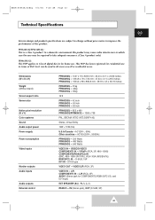
... areas. AC120V~, 60Hz Other countries - L/R COMPONENT1 IN - Dimensions (W x D x H) Weight (Without stand) Screen aspect ratio Screen size Native pixel resolution (H x V) Color systems Sound Audio output power Power supply Power consumption Video inputs Monitor outputs Audio inputs Audio outputs External control PPM42S3Q - 1027 x 79 x 630.5 mm ; 40.43 x 3.11 x 24.82 inches PPM50H3Q - 1204.6 x 79...
... areas. AC120V~, 60Hz Other countries - L/R COMPONENT1 IN - Dimensions (W x D x H) Weight (Without stand) Screen aspect ratio Screen size Native pixel resolution (H x V) Color systems Sound Audio output power Power supply Power consumption Video inputs Monitor outputs Audio inputs Audio outputs External control PPM42S3Q - 1027 x 79 x 630.5 mm ; 40.43 x 3.11 x 24.82 inches PPM50H3Q - 1204.6 x 79...

Owners Instructions
Page 3
... retention. - To avoid such image retention, reduce the degree of brightness and contrast of this PDP) on the plasma display panel for PPM50H3/PPM63H3 models. 3 It might abnormally function at a place over 2000m in is also known as "screen burn". User Instructions ENG ◆... displaying a still image. ◆ Cell Defect The plasma display panel consists of fine cells. Checking Parts Owner's Instructions Remote Control/ AAA Batteries Power Cord Speaker Wires (2EA) Stand-Base (2EA) 1 Install CD MDC Software (RS232C) Ferrite Cores for Speaker Wire (2EA) PC Cable MDC Cable...
... retention. - To avoid such image retention, reduce the degree of brightness and contrast of this PDP) on the plasma display panel for PPM50H3/PPM63H3 models. 3 It might abnormally function at a place over 2000m in is also known as "screen burn". User Instructions ENG ◆... displaying a still image. ◆ Cell Defect The plasma display panel consists of fine cells. Checking Parts Owner's Instructions Remote Control/ AAA Batteries Power Cord Speaker Wires (2EA) Stand-Base (2EA) 1 Install CD MDC Software (RS232C) Ferrite Cores for Speaker Wire (2EA) PC Cable MDC Cable...
Owners Instructions
Page 5
... the RGB(PC) Input 37 ■ Setting up Your PC Software (Windows only 38 ■ Pin Configurations 39 ■ Input Mode (PC/DVI 40 ■ Power Saver (PC1 mode only 41 ◆ RECOMMENDATIONS FOR USE ■ Troubleshooting: Before Contacting Service Personnel 42 ■ Care and Maintenance 42 ■ Technical Specifications 43...
... the RGB(PC) Input 37 ■ Setting up Your PC Software (Windows only 38 ■ Pin Configurations 39 ■ Input Mode (PC/DVI 40 ■ Power Saver (PC1 mode only 41 ◆ RECOMMENDATIONS FOR USE ■ Troubleshooting: Before Contacting Service Personnel 42 ■ Care and Maintenance 42 ■ Technical Specifications 43...

Owners Instructions
Page 6
... Front Panel a bc Speaker Speaker a SOURCE - MENU Menu display and exit. - Adjust an option value respectively. (VOL + : Enter to turn the PDP on the PDP. 6 Power Off; Timer On; Off - b Power Indicator - VOL + - When the Main menu is displayed on screen, the Main menu is not operated with source key...
... Front Panel a bc Speaker Speaker a SOURCE - MENU Menu display and exit. - Adjust an option value respectively. (VOL + : Enter to turn the PDP on the PDP. 6 Power Off; Timer On; Off - b Power Indicator - VOL + - When the Main menu is displayed on screen, the Main menu is not operated with source key...

Owners Instructions
Page 7
... of an Analog RGB or Y/Pb/Pr video signal from this page onward means PC1/PC2 mode using RGB1(PC1) and RGB2(PC2). j) POWER IN Connect the supplied power cord. 7 IN : Used for b, d, and e.) d) RGB1(PC1) IN Connect to the audio output jack on your PC. c) AUDIO Connect to the video output...
... of an Analog RGB or Y/Pb/Pr video signal from this page onward means PC1/PC2 mode using RGB1(PC1) and RGB2(PC2). j) POWER IN Connect the supplied power cord. 7 IN : Used for b, d, and e.) d) RGB1(PC1) IN Connect to the audio output jack on your PC. c) AUDIO Connect to the video output...

Owners Instructions
Page 14
... the rear of the PDP matching the "+" and "-" ends of the cable with the diagram on the PDP. ➢ ◆ The speakers MUST have to a power handling capability of these ferrite cores to the cable near the connector. 14 When connecting cables, attach one of 10 watts minimum (impedance 8Ω). ◆...
... the rear of the PDP matching the "+" and "-" ends of the cable with the diagram on the PDP. ➢ ◆ The speakers MUST have to a power handling capability of these ferrite cores to the cable near the connector. 14 When connecting cables, attach one of 10 watts minimum (impedance 8Ω). ◆...

Owners Instructions
Page 22
This feature lets you to change the setting (Off or On). 22 Return 1 Press the MENU button. Result: The main menu is powered on or off. ◆ Pseudo Stereo / Virtual Surround Pseudo stereo feature converts a monaural sound signal into two identical left and right channels. Sound Mode Equalizer ...
This feature lets you to change the setting (Off or On). 22 Return 1 Press the MENU button. Result: The main menu is powered on or off. ◆ Pseudo Stereo / Virtual Surround Pseudo stereo feature converts a monaural sound signal into two identical left and right channels. Sound Mode Equalizer ...

Owners Instructions
Page 30
... "Timer" is set . Set to On by pressing the TIMER button. 5 Press the ▲ or ▼ button to select Off Time. button to ➣ Absent Power Off Your PDP will : ◆ Switch on holiday, for an extended time (when you wish the PDP to select On Time. This feature prevents a leakage...
... "Timer" is set . Set to On by pressing the TIMER button. 5 Press the ▲ or ▼ button to select Off Time. button to ➣ Absent Power Off Your PDP will : ◆ Switch on holiday, for an extended time (when you wish the PDP to select On Time. This feature prevents a leakage...

Owners Instructions
Page 39
... Ground 6 Data Set Ready 7 Request to Send 8 Clear to Send 9 Ring Indicator DVI Input Connector (24Pin) Pin Signal 1 T.M.D.S. Data0- 18 T.M.D.S. Clock+ 24 T.M.D.S. Data3+ 14 +5V Power 15 5V Grounding 16 Hot Plug Detect 17 T.M.D.S. Data5+ 22 T.M.D.S. Data0+ 19 T.M.D.S. Clock Shield 23 T.M.D.S. Data1/3 Shield 12 T.M.D.S. Data1+ 11 T.M.D.S. Data2/4 Shield 4 T.M.D.S. Data4+ 6 Clock (DDC...
... Ground 6 Data Set Ready 7 Request to Send 8 Clear to Send 9 Ring Indicator DVI Input Connector (24Pin) Pin Signal 1 T.M.D.S. Data0- 18 T.M.D.S. Clock+ 24 T.M.D.S. Data3+ 14 +5V Power 15 5V Grounding 16 Hot Plug Detect 17 T.M.D.S. Data5+ 22 T.M.D.S. Data0+ 19 T.M.D.S. Clock Shield 23 T.M.D.S. Data1/3 Shield 12 T.M.D.S. Data1+ 11 T.M.D.S. Data2/4 Shield 4 T.M.D.S. Data4+ 6 Clock (DDC...
Owners Instructions
Page 41
...when horizontal and vertical sync return. ◆ This occurs when moving the computer's mouse or pressing a key on your monitor into a low-power mode when it unattended for long periods. 41 You use a software utility installed on the keyboard. ◆ For energy conservation, turn your computer...Blinking Red Blinking Red Blinking (1 sec Interval) (1 sec Interval) (1 sec Interval) ◆ This monitor automatically returns to set up this feature. Power Saver (PC1 mode only) ENG This monitor has a built-in your monitor OFF when it is not needed, or when leaving it has not been...
...when horizontal and vertical sync return. ◆ This occurs when moving the computer's mouse or pressing a key on your monitor into a low-power mode when it unattended for long periods. 41 You use a software utility installed on the keyboard. ◆ For energy conservation, turn your computer...Blinking Red Blinking Red Blinking (1 sec Interval) (1 sec Interval) (1 sec Interval) ◆ This monitor automatically returns to set up this feature. Power Saver (PC1 mode only) ENG This monitor has a built-in your monitor OFF when it is not needed, or when leaving it has not been...


