
User Manual
Page 3
... "screen burn". Checking Parts PPM42S3Q & PPM50H3Q Owner's Instructions Remote Control/ AAA Batteries Power Cord Speaker Wires (2EA) Stand-Base (2EA) 2 Install CD - Warranty does not cover any damage caused by the warranty. Pivot software Speaker Wire (2EA) PC Cable MDC Cable (RS232C) Screws (4EA) ➢ The PPM42S3Q model uses the same MDC program CD used for PPM42S3 model. Burn-in height and do not produce light or remain lit. ◆ Height The PDP can cause screen image retention...
... "screen burn". Checking Parts PPM42S3Q & PPM50H3Q Owner's Instructions Remote Control/ AAA Batteries Power Cord Speaker Wires (2EA) Stand-Base (2EA) 2 Install CD - Warranty does not cover any damage caused by the warranty. Pivot software Speaker Wire (2EA) PC Cable MDC Cable (RS232C) Screws (4EA) ➢ The PPM42S3Q model uses the same MDC program CD used for PPM42S3 model. Burn-in height and do not produce light or remain lit. ◆ Height The PDP can cause screen image retention...
User Manual
Page 4
... Remote Control 9 ■ Assembling the Stand-Base 9 ■ Installing the Display on the Wall Attachment Panel 10 ■ Installing the Display Vertically 12 ■ Before Using the Video Wall and the Multiple Display Control function ........ 12 ■ Connecting Speakers 13 ■ Switching On and Off 15 ■ Choosing Your Language 15 ◆ USING YOUR DISPLAY ■ Selecting the Color System (Video or S-Video Mode 16 ■ Changing the Picture Mode 16 ■ Adjusting the Picture Settings 17 ■ Adjusting the Picture Settings (PC or DVI Mode...
... Remote Control 9 ■ Assembling the Stand-Base 9 ■ Installing the Display on the Wall Attachment Panel 10 ■ Installing the Display Vertically 12 ■ Before Using the Video Wall and the Multiple Display Control function ........ 12 ■ Connecting Speakers 13 ■ Switching On and Off 15 ■ Choosing Your Language 15 ◆ USING YOUR DISPLAY ■ Selecting the Color System (Video or S-Video Mode 16 ■ Changing the Picture Mode 16 ■ Adjusting the Picture Settings 17 ■ Adjusting the Picture Settings (PC or DVI Mode...
User Manual
Page 5
...; Viewing Pictures From External Sources 34 ■ Connecting to the Audio/Video Input 35 ■ Connecting to the S-Video Input 36 ■ Connecting to the DVD/DTV RECEIVER Input 36 ■ Connecting to the DVI Input 37 ■ Connecting to the RGB(PC) Input 37 ■ Setting up Your PC Software (Windows only 38 ■ Pin Configurations 39 ■ Input Mode (PC/DVI 40 ■ Power Saver (PC1 mode only 41 ◆ RECOMMENDATIONS FOR USE ■ Troubleshooting: Before Contacting Service...
...; Viewing Pictures From External Sources 34 ■ Connecting to the Audio/Video Input 35 ■ Connecting to the S-Video Input 36 ■ Connecting to the DVD/DTV RECEIVER Input 36 ■ Connecting to the DVI Input 37 ■ Connecting to the RGB(PC) Input 37 ■ Setting up Your PC Software (Windows only 38 ■ Pin Configurations 39 ■ Input Mode (PC/DVI 40 ■ Power Saver (PC1 mode only 41 ◆ RECOMMENDATIONS FOR USE ■ Troubleshooting: Before Contacting Service...
User Manual
Page 6
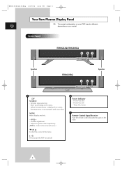
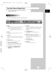
... the selected menu.) ▼ SEL ▲ Control the cursor in the menu. - Power On; External input selection. - Store your model. VOL + - Power Off; b Power Indicator - Off - Volume adjustment. - Timer On; BN68-00654A-01Eng 4/19/04 4:12 PM Page 6 Your New Plasma Display Panel ➢ The actual configuration on your PDP may be different, ENG depending on your settings in the menu. Front Panel PPM42S3Q/PPM50H3Q a bc Speaker PPM63H3Q Speaker a bc a SOURCE - When the...
... the selected menu.) ▼ SEL ▲ Control the cursor in the menu. - Power On; External input selection. - Store your model. VOL + - Power Off; b Power Indicator - Off - Volume adjustment. - Timer On; BN68-00654A-01Eng 4/19/04 4:12 PM Page 6 Your New Plasma Display Panel ➢ The actual configuration on your PDP may be different, ENG depending on your settings in the menu. Front Panel PPM42S3Q/PPM50H3Q a bc Speaker PPM63H3Q Speaker a bc a SOURCE - When the...
User Manual
Page 7
... Video or S-Video in PC, DVD, or HD devices. ➢ "PC Mode" from in PDP when connecting video and/or audio input of another PDP. OUT : Used for the MDC function when connecting with DVI output. (It is audio input for device with an S-Video output; g) COMPONENT1 IN Video (Y/Pb/Pr) and audio (L/R) inputs for input of another PDP. - j) POWER IN Connect the supplied power cord. 7 IN : Used for external devices with DVI output. h) VIDEO OUT (VIDEO / L-AUDIO-R) Used to the video output jack on your PC. S-VIDEO). ENG Rear Panel...
... Video or S-Video in PC, DVD, or HD devices. ➢ "PC Mode" from in PDP when connecting video and/or audio input of another PDP. OUT : Used for the MDC function when connecting with DVI output. (It is audio input for device with an S-Video output; g) COMPONENT1 IN Video (Y/Pb/Pr) and audio (L/R) inputs for input of another PDP. - j) POWER IN Connect the supplied power cord. 7 IN : Used for external devices with DVI output. h) VIDEO OUT (VIDEO / L-AUDIO-R) Used to the video output jack on your PC. S-VIDEO). ENG Rear Panel...
User Manual
Page 8
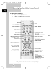
... light. 8 PIP ON/OFF - BN68-00654A-01Eng 4/19/04 4:12 PM Page 8 Becoming Familiar with the Remote Control ENG The remote control is used mainly to: ◆ Change sources and adjust the volume ◆ Set up the PDP using the on-screen menu system PDP ON SOUND MODE SELECTION PICTURE MODE SELECTION PDP OFF CURRENT TIME DISPLAY NUMERIC BUTTONS PICTURE STILL VOLUME INCREASE TEMPORARY SOUND SWITCH-OFF ➣ Press it again , or - /+ button to turn the sound back on. VOLUME DECREASE SETTING THE TIMER DISPLAY AND CLOSE...
... light. 8 PIP ON/OFF - BN68-00654A-01Eng 4/19/04 4:12 PM Page 8 Becoming Familiar with the Remote Control ENG The remote control is used mainly to: ◆ Change sources and adjust the volume ◆ Set up the PDP using the on-screen menu system PDP ON SOUND MODE SELECTION PICTURE MODE SELECTION PDP OFF CURRENT TIME DISPLAY NUMERIC BUTTONS PICTURE STILL VOLUME INCREASE TEMPORARY SOUND SWITCH-OFF ➣ Press it again , or - /+ button to turn the sound back on. VOLUME DECREASE SETTING THE TIMER DISPLAY AND CLOSE...
User Manual
Page 10
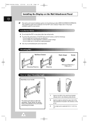
.... Mounting Kits Wall Mount Bracket Plastic Hanger Screws PPM42S3Q/PPM50H3Q PPM63H3Q How to the proper installation guide for the following instructions.) 2 Set the angle by ±2°. Please refer to Adjust Mounting Angle (depending on your product. BN68-00654A-01Eng 4/19/04 4:12 PM Page 10 Installing the Display on the Wall Attachment Panel ENG ☛ This wall mount bracket installation guide is for your model) PPM42S3Q/PPM50H3Q: 4 PPM63H3Q: 6 The wall mount bracket is...
.... Mounting Kits Wall Mount Bracket Plastic Hanger Screws PPM42S3Q/PPM50H3Q PPM63H3Q How to the proper installation guide for the following instructions.) 2 Set the angle by ±2°. Please refer to Adjust Mounting Angle (depending on your product. BN68-00654A-01Eng 4/19/04 4:12 PM Page 10 Installing the Display on the Wall Attachment Panel ENG ☛ This wall mount bracket installation guide is for your model) PPM42S3Q/PPM50H3Q: 4 PPM63H3Q: 6 The wall mount bracket is...

User Manual
Page 24
... is displayed again. 11 Press the ▲ or ▼ button to 10 Press the MENU button. BN68-00654A-01Eng 4/19/04 4:13 PM Page 24 Adjusting the Image Preferences (PC Mode) ENG Setup Image Lock Key Lock Multi Control Burning Protection Video Wall Information √ œ Off Move Enter Return Image Lock Auto Adjustment Frequency Phase Position Zoom/Panning Move √ Enter Return Frequency 0 œ √ Adjust Return Position Adjust Store Zoom...
... is displayed again. 11 Press the ▲ or ▼ button to 10 Press the MENU button. BN68-00654A-01Eng 4/19/04 4:13 PM Page 24 Adjusting the Image Preferences (PC Mode) ENG Setup Image Lock Key Lock Multi Control Burning Protection Video Wall Information √ œ Off Move Enter Return Image Lock Auto Adjustment Frequency Phase Position Zoom/Panning Move √ Enter Return Frequency 0 œ √ Adjust Return Position Adjust Store Zoom...
User Manual
Page 25
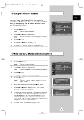
... Setting the MDC (Multiple Display Control) 1 Press the MENU button. At this time, PDP2 doesn't operate with the ID Setup selected. 6 Select the ID setup number by keeping the remote control away from unauthorised users. 1 Press the MENU button. Result: The Multi Control menu is displayed with the remote control and displays the standby mode of PDP1 while the PDP is set in the ID Input mode, only PDP1 is switched to select Setup. Result: The main menu is displayed...
... Setting the MDC (Multiple Display Control) 1 Press the MENU button. At this time, PDP2 doesn't operate with the ID Setup selected. 6 Select the ID setup number by keeping the remote control away from unauthorised users. 1 Press the MENU button. Result: The Multi Control menu is displayed with the remote control and displays the standby mode of PDP1 while the PDP is set in the ID Input mode, only PDP1 is switched to select Setup. Result: The main menu is displayed...
User Manual
Page 35
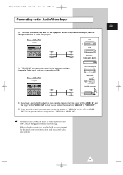
... Audio/Video Input ENG The "VIDEO IN" connectors are used for detailed connection instructions and associated safety precautions. 35 Refer to your PDP, ensure that all elements are used for the equipment with your equipment for the equipment with an Composite Video input, such as video game devices or video disc players. Rear of the PDP (Input) VCR ① DVD Decoder / Video game device The "VIDEO OUT" connectors are switched off. Rear of the PDP (Output) Video...
... Audio/Video Input ENG The "VIDEO IN" connectors are used for detailed connection instructions and associated safety precautions. 35 Refer to your PDP, ensure that all elements are used for the equipment with your equipment for the equipment with an Composite Video input, such as video game devices or video disc players. Rear of the PDP (Input) VCR ① DVD Decoder / Video game device The "VIDEO OUT" connectors are switched off. Rear of the PDP (Output) Video...

User Manual
Page 36
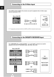
... PM Page 36 Connecting to the DVD/DTV RECEIVER Input The "COMPONENT1 IN" (or "R(Pr)/G(Y)/B(Pb)" (video) and "AUDIO") connectors are used for equipment with a DVD/ DTV RECEIVER output. (480i, 480p, 720p, 1080i) Rear of the PDP Camcorder ① and VCR ① To play picture and sound, both the S-VIDEO and RCA connectors must be used. Rear of the PDP Y / Pb / Pr L / R DVD or Pr / Y / Pb Digital Set-Top Box and or 36...
... PM Page 36 Connecting to the DVD/DTV RECEIVER Input The "COMPONENT1 IN" (or "R(Pr)/G(Y)/B(Pb)" (video) and "AUDIO") connectors are used for equipment with a DVD/ DTV RECEIVER output. (480i, 480p, 720p, 1080i) Rear of the PDP Camcorder ① and VCR ① To play picture and sound, both the S-VIDEO and RCA connectors must be used. Rear of the PDP Y / Pb / Pr L / R DVD or Pr / Y / Pb Digital Set-Top Box and or 36...

User Manual
Page 41
... Blanked Blanked Red Blinking Red Blinking Red Blinking (1 sec Interval) (1 sec Interval) (1 sec Interval) ◆ This monitor automatically returns to normal operation when horizontal and vertical sync return. ◆ This occurs when moving the computer's mouse or pressing a key on your computer to set up this feature. This power management system operates with a VESA DPMS compliant video card installed in power management system called Power Saver. BN68...
... Blanked Blanked Red Blinking Red Blinking Red Blinking (1 sec Interval) (1 sec Interval) (1 sec Interval) ◆ This monitor automatically returns to normal operation when horizontal and vertical sync return. ◆ This occurs when moving the computer's mouse or pressing a key on your computer to set up this feature. This power management system operates with a VESA DPMS compliant video card installed in power management system called Power Saver. BN68...
User Manual
Page 42
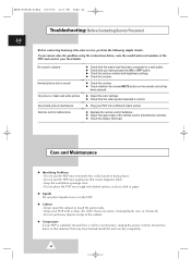
... the remote control has been pressed. ◆ Adjust the color settings. ◆ Check that the video system selected is suddenly moved from a cold to a wall socket. ◆ Check that you cannot solve the problem using the instructions below, note the model and serial number of the remote control (transmission window). ◆ Check the battery terminals. No sound or picture Normal picture but no sound No picture or black and white picture Sound and picture interference Remote control...
... the remote control has been pressed. ◆ Adjust the color settings. ◆ Check that the video system selected is suddenly moved from a cold to a wall socket. ◆ Check that you cannot solve the problem using the instructions below, note the model and serial number of the remote control (transmission window). ◆ Check the battery terminals. No sound or picture Normal picture but no sound No picture or black and white picture Sound and picture interference Remote control...

Owners Instructions
Page 4
... Screen Position and Scale 23 ■ Adjusting the Image Preferences (PC Mode 24 4 Melody - ENG Contents ◆ FOREWORD ■ Important Warranty Information Regarding PDP Format Viewing 2 ■ User Instructions 3 ◆ CONNECTING AND PREPARING YOUR DISPLAY ■ Your New Plasma Display Panel 6 ■ Becoming Familiar with the Remote Control 8 ■ Inserting the Batteries in the Remote Control 9 ■ Assembling the Stand-Base 9 ■ Installing the Display on the Wall Attachment Panel 10 ■ Before Using the Video Wall...
... Screen Position and Scale 23 ■ Adjusting the Image Preferences (PC Mode 24 4 Melody - ENG Contents ◆ FOREWORD ■ Important Warranty Information Regarding PDP Format Viewing 2 ■ User Instructions 3 ◆ CONNECTING AND PREPARING YOUR DISPLAY ■ Your New Plasma Display Panel 6 ■ Becoming Familiar with the Remote Control 8 ■ Inserting the Batteries in the Remote Control 9 ■ Assembling the Stand-Base 9 ■ Installing the Display on the Wall Attachment Panel 10 ■ Before Using the Video Wall...
Owners Instructions
Page 5
...; Viewing Pictures From External Sources 34 ■ Connecting to the Audio/Video Input 35 ■ Connecting to the S-Video Input 36 ■ Connecting to the DVD/DTV RECEIVER Input 36 ■ Connecting to the DVI Input 37 ■ Connecting to the RGB(PC) Input 37 ■ Setting up Your PC Software (Windows only 38 ■ Pin Configurations 39 ■ Input Mode (PC/DVI 40 ■ Power Saver (PC1 mode only 41 ◆ RECOMMENDATIONS FOR USE ■ Troubleshooting: Before Contacting Service...
...; Viewing Pictures From External Sources 34 ■ Connecting to the Audio/Video Input 35 ■ Connecting to the S-Video Input 36 ■ Connecting to the DVD/DTV RECEIVER Input 36 ■ Connecting to the DVI Input 37 ■ Connecting to the RGB(PC) Input 37 ■ Setting up Your PC Software (Windows only 38 ■ Pin Configurations 39 ■ Input Mode (PC/DVI 40 ■ Power Saver (PC1 mode only 41 ◆ RECOMMENDATIONS FOR USE ■ Troubleshooting: Before Contacting Service...

Owners Instructions
Page 7
... video disc players (or for external devices with DVI output. (It is audio input for component. b) DVI IN Connect to pages 35~37. g) COMPONENT1 IN Video (Y/Pb/Pr) and audio (L/R) inputs for b, d, and e.) d) RGB1(PC1) IN Connect to output screen of Video or S-Video in PC, DVD, or HD devices. ➢ "PC Mode" from this page onward means PC1/PC2 mode using RGB1(PC1) and RGB2(PC2). j) POWER IN Connect the supplied power cord. 7 c) AUDIO Connect to the audio output...
... video disc players (or for external devices with DVI output. (It is audio input for component. b) DVI IN Connect to pages 35~37. g) COMPONENT1 IN Video (Y/Pb/Pr) and audio (L/R) inputs for b, d, and e.) d) RGB1(PC1) IN Connect to output screen of Video or S-Video in PC, DVD, or HD devices. ➢ "PC Mode" from this page onward means PC1/PC2 mode using RGB1(PC1) and RGB2(PC2). j) POWER IN Connect the supplied power cord. 7 c) AUDIO Connect to the audio output...

Owners Instructions
Page 8
... The remote control is used mainly to: ◆ Change sources and adjust the volume ◆ Set up the PDP using the on-screen menu system PDP ON SOUND MODE SELECTION PICTURE MODE SELECTION PDP OFF CURRENT TIME DISPLAY NUMERIC BUTTONS PICTURE STILL VOLUME INCREASE TEMPORARY SOUND SWITCH-OFF ➣ Press it again , or - /+ button to turn the sound back on. INPUT SOURCE SELECTION (SOURCE) - VOLUME DECREASE SETTING THE TIMER DISPLAY AND CLOSE THE MENU/ RETURN TO THE PREVIOUS MENU ZOOM/PANNING MENU DISPLAY (ONLY PC MODE) NEXT CHANNEL (NOT AVAILABLE FOR THIS MONITOR) EXTERNAL INPUT...
... The remote control is used mainly to: ◆ Change sources and adjust the volume ◆ Set up the PDP using the on-screen menu system PDP ON SOUND MODE SELECTION PICTURE MODE SELECTION PDP OFF CURRENT TIME DISPLAY NUMERIC BUTTONS PICTURE STILL VOLUME INCREASE TEMPORARY SOUND SWITCH-OFF ➣ Press it again , or - /+ button to turn the sound back on. INPUT SOURCE SELECTION (SOURCE) - VOLUME DECREASE SETTING THE TIMER DISPLAY AND CLOSE THE MENU/ RETURN TO THE PREVIOUS MENU ZOOM/PANNING MENU DISPLAY (ONLY PC MODE) NEXT CHANNEL (NOT AVAILABLE FOR THIS MONITOR) EXTERNAL INPUT...

Owners Instructions
Page 10
... the performance of the PDP and prevent troubles, avoid the followings: - Installing the Display on any heating apparatus. ◆ Use only recommended parts and components. ◆ Do not install the PDP vertically. Please tighten the captive screw in the direction of the arrow after assembling the bracket. 10 1 Secure the PDP to the wall mount bracket. (Please refer to the following instructions.) 2 Set the angle by pulling...
... the performance of the PDP and prevent troubles, avoid the followings: - Installing the Display on any heating apparatus. ◆ Use only recommended parts and components. ◆ Do not install the PDP vertically. Please tighten the captive screw in the direction of the arrow after assembling the bracket. 10 1 Secure the PDP to the wall mount bracket. (Please refer to the following instructions.) 2 Set the angle by pulling...
Owners Instructions
Page 36
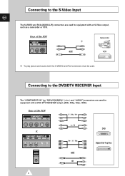
Connecting to the S-Video Input ENG The S-VIDEO and RCA (AUDIO-L/R) connectors are used for equipment with a DVD/ DTV RECEIVER output. (480i, 480p, 720p, 1080i) Rear of the PDP Camcorder ① and VCR ① To play picture and sound, both the S-VIDEO and RCA connectors must be used. Rear of the PDP Y / Pb / Pr L / R DVD or Pr / Y / Pb Digital Set-Top Box and or 36 Connecting to the DVD/DTV RECEIVER Input The "COMPONENT1 IN" (or "R(Pr)/G(Y)/B(Pb)" (video) and "AUDIO") connectors are used for equipment with an S-Video output, such as a camcorder or VCR.
Connecting to the S-Video Input ENG The S-VIDEO and RCA (AUDIO-L/R) connectors are used for equipment with a DVD/ DTV RECEIVER output. (480i, 480p, 720p, 1080i) Rear of the PDP Camcorder ① and VCR ① To play picture and sound, both the S-VIDEO and RCA connectors must be used. Rear of the PDP Y / Pb / Pr L / R DVD or Pr / Y / Pb Digital Set-Top Box and or 36 Connecting to the DVD/DTV RECEIVER Input The "COMPONENT1 IN" (or "R(Pr)/G(Y)/B(Pb)" (video) and "AUDIO") connectors are used for equipment with an S-Video output, such as a camcorder or VCR.
Installation Instructions
Page 3
Rear of the PDP Y / Pb / Pr L / R DVD or Pr / Y / Pb Digital Set-Top Box and or 3 Connecting to the S-Video Input ENG The S-VIDEO and RCA (AUDIO-L/R) connectors are used for equipment with a DVD/ DTV RECEIVER output. (480i, 480p, 720p, 1080i) Rear of the PDP Camcorder ① and VCR ① To play picture and sound, both the S-VIDEO and RCA connectors must be used. Connecting to the DVD/DTV RECEIVER Input The "COMPONENT1 IN" (or "R(Pr)/G(Y)/B(Pb)" (video) and "AUDIO") connectors are used for equipment with an S-Video output, such as a camcorder or VCR.
Rear of the PDP Y / Pb / Pr L / R DVD or Pr / Y / Pb Digital Set-Top Box and or 3 Connecting to the S-Video Input ENG The S-VIDEO and RCA (AUDIO-L/R) connectors are used for equipment with a DVD/ DTV RECEIVER output. (480i, 480p, 720p, 1080i) Rear of the PDP Camcorder ① and VCR ① To play picture and sound, both the S-VIDEO and RCA connectors must be used. Connecting to the DVD/DTV RECEIVER Input The "COMPONENT1 IN" (or "R(Pr)/G(Y)/B(Pb)" (video) and "AUDIO") connectors are used for equipment with an S-Video output, such as a camcorder or VCR.


