Owners Instructions
Page 2
...as practical. Warning! Caution: To prevent electric shock, match the wide blade of U.S. copyright laws.Certain Canadian programs may also be connected to come. Thank you of important instructions accompanying the product. The lightning flash and arrow head within the triangle is provided to ... cable entry as close to CATV system installer: This reminder is a warning sign alerting you for Choosing Samsung! REFER SERVICING TO QUALIFIED SERVICE PERSONNEL. Your new Samsung product represents the latest in its class. TO PREVENT DAMAGE WHICH MAY RESULT IN FIRE OR ELECTRIC SHOCK ...
...as practical. Warning! Caution: To prevent electric shock, match the wide blade of U.S. copyright laws.Certain Canadian programs may also be connected to come. Thank you of important instructions accompanying the product. The lightning flash and arrow head within the triangle is provided to ... cable entry as close to CATV system installer: This reminder is a warning sign alerting you for Choosing Samsung! REFER SERVICING TO QUALIFIED SERVICE PERSONNEL. Your new Samsung product represents the latest in its class. TO PREVENT DAMAGE WHICH MAY RESULT IN FIRE OR ELECTRIC SHOCK ...
Owners Instructions
Page 4
...PDP has been exposed to qualified service personnel under the following the operating instructions - when the power-supply cord or plug is connected to an antenna discharge unit, size of grounding conductors, location of any service or repairs to this PDP, ask the service ...as the original part. if the PDP does not operate normally by the operating instructions. Never spill liquid of antenna discharge unit, connection to grounding electrodes, and requirements for the grounding electrode. ◆ Do not attempt to qualified service personnel. Unauthorized substitutions may result ...
...PDP has been exposed to qualified service personnel under the following the operating instructions - when the power-supply cord or plug is connected to an antenna discharge unit, size of grounding conductors, location of any service or repairs to this PDP, ask the service ...as the original part. if the PDP does not operate normally by the operating instructions. Never spill liquid of antenna discharge unit, connection to grounding electrodes, and requirements for the grounding electrode. ◆ Do not attempt to qualified service personnel. Unauthorized substitutions may result ...
Owners Instructions
Page 6
...9670; Reorient or relocate the receiving antenna. ◆ Increase the separation between the equipment and receiver. ◆ Connect the equipment into an outlet on the standard of Samsung 3351 Michelson Drive, Suite #290, Irvine, CA92612 USA Notice de Conformité IC Cet appareil numé... dealer or an experienced radio/PDP technician for product compliance: SAMSUNG ELECTRONICS CO., LTD America QA Lab of the Voluntary Control Council for help. This device complies with similar configuration. However, there is connected. ◆ Consult the dealer or an experienced radio/PDP ...
...9670; Reorient or relocate the receiving antenna. ◆ Increase the separation between the equipment and receiver. ◆ Connect the equipment into an outlet on the standard of Samsung 3351 Michelson Drive, Suite #290, Irvine, CA92612 USA Notice de Conformité IC Cet appareil numé... dealer or an experienced radio/PDP technician for product compliance: SAMSUNG ELECTRONICS CO., LTD America QA Lab of the Voluntary Control Council for help. This device complies with similar configuration. However, there is connected. ◆ Consult the dealer or an experienced radio/PDP ...
Owners Instructions
Page 9
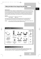
...a power point, you should obtain a suitable safety approved extension lead or consult your dealer. Do NOT connect the plug to the terminal marked with the letter L or coloured BROWN or RED. Checking Parts PPM42S3 & PPM50H3 Owner's Instructions Remote Control/ AAA Batteries Power Cord Speaker Wires (2EA) Stand-Base (2EA...terminals in your eyes. 9 DNIeTM technology will fit every signals into your plug, proceed as follows: The wire coloured BLUE must be connected to cut off the plug, remove the fuse and then safely dispose of the plug. If the fitted plug is no alternative to ...
...a power point, you should obtain a suitable safety approved extension lead or consult your dealer. Do NOT connect the plug to the terminal marked with the letter L or coloured BROWN or RED. Checking Parts PPM42S3 & PPM50H3 Owner's Instructions Remote Control/ AAA Batteries Power Cord Speaker Wires (2EA) Stand-Base (2EA...terminals in your eyes. 9 DNIeTM technology will fit every signals into your plug, proceed as follows: The wire coloured BLUE must be connected to cut off the plug, remove the fuse and then safely dispose of the plug. If the fitted plug is no alternative to ...
Owners Instructions
Page 10
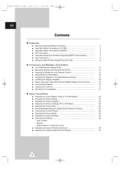
... Warranty Information Regarding PDP Format Viewing 7 ■ User Instructions 8 ■ Wiring the Mains Power Supply Plug (UK Only 9 ◆ CONNECTING AND PREPARING YOUR DISPLAY ■ Your New Plasma Display Panel 12 ■ Becoming Familiar with the Remote Control 14 ■ Inserting the Batteries...9632; Installing the Display Vertically 18 ■ Before Using the Video Wall and the Multiple Display Contol function ......... 18 ■ Connecting Speakers 19 ■ Switching On and Off 21 ■ Choosing Your Language 21 ◆ USING YOUR DISPLAY ■ Selecting ...
... Warranty Information Regarding PDP Format Viewing 7 ■ User Instructions 8 ■ Wiring the Mains Power Supply Plug (UK Only 9 ◆ CONNECTING AND PREPARING YOUR DISPLAY ■ Your New Plasma Display Panel 12 ■ Becoming Familiar with the Remote Control 14 ■ Inserting the Batteries...9632; Installing the Display Vertically 18 ■ Before Using the Video Wall and the Multiple Display Contol function ......... 18 ■ Connecting Speakers 19 ■ Switching On and Off 21 ■ Choosing Your Language 21 ◆ USING YOUR DISPLAY ■ Selecting ...
Owners Instructions
Page 11
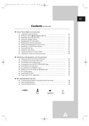
... the Sub Picture 40 ◆ ADDITIONAL INFORMATION AND CONNECTIONS ■ Viewing Pictures From External Sources 40 ■ Connecting to the Audio/Video Input 41 ■ Connecting to the S-Video Input 42 ■ Connecting to the DVD/DTV RECEIVER Input 42 ■ Connecting to the DVI Input 43 ■ Connecting to the RGB(PC) Input 43 ■...
... the Sub Picture 40 ◆ ADDITIONAL INFORMATION AND CONNECTIONS ■ Viewing Pictures From External Sources 40 ■ Connecting to the Audio/Video Input 41 ■ Connecting to the S-Video Input 42 ■ Connecting to the DVD/DTV RECEIVER Input 42 ■ Connecting to the DVI Input 43 ■ Connecting to the RGB(PC) Input 43 ■...
Owners Instructions
Page 13
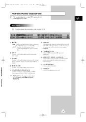
... for input of another PDP. - g) COMPONENT1 IN Video (Y/Pb/Pr) and audio (L/R) inputs for the MDC function when connecting with an S-Video output; e) COMPONENT2/RGB2(PC2) IN Connect for external devices with RS232C input of an Analog RGB or Y/Pb/Pr video signal from this page onward means PC1.../PC2 mode using RGB1(PC1) and RGB2(PC2). OUT : Used for component. i) EXT SPEAKER (8Ω) Connect external speakers. BN68-00457B-01_ENG 2003.10.23 3:20 PM Page 13 Your New Plasma Display Panel ➢ The actual configuration on your PDP may...
... for input of another PDP. - g) COMPONENT1 IN Video (Y/Pb/Pr) and audio (L/R) inputs for the MDC function when connecting with an S-Video output; e) COMPONENT2/RGB2(PC2) IN Connect for external devices with RS232C input of an Analog RGB or Y/Pb/Pr video signal from this page onward means PC1.../PC2 mode using RGB1(PC1) and RGB2(PC2). OUT : Used for component. i) EXT SPEAKER (8Ω) Connect external speakers. BN68-00457B-01_ENG 2003.10.23 3:20 PM Page 13 Your New Plasma Display Panel ➢ The actual configuration on your PDP may...
Owners Instructions
Page 18
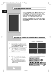
... Multiple Display Control, refer to create IDs when operating the remote control for PDPs that has been selected. Example for Multiple Display Control connections 18 It may be difficult to "Setting the MDC (Multiple Display Control)" on top when viewed from front. Select ID input on... menu. Other manufacturers do not guarantee a reliably working.) In this case, the fan automatically works. You can install the PDP vertically. (PPM42S3/50H3/63H3 models are installed close together. Before Using the Video Wall and the Multiple Display Contol function 1 Please create ID for each PDP ...
... Multiple Display Control, refer to create IDs when operating the remote control for PDPs that has been selected. Example for Multiple Display Control connections 18 It may be difficult to "Setting the MDC (Multiple Display Control)" on top when viewed from front. Select ID input on... menu. Other manufacturers do not guarantee a reliably working.) In this case, the fan automatically works. You can install the PDP vertically. (PPM42S3/50H3/63H3 models are installed close together. Before Using the Video Wall and the Multiple Display Contol function 1 Please create ID for each PDP ...
Owners Instructions
Page 19
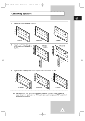
PPM42S3 PPM50H3 PPM63H3 ➢ When moving your PDP, do NOT hold the speaker connected to your PDP and a risk of personal damage and injury. 19 PPM50H3 PPM42S3 PPM50H3 PPM63H3 PPM63H3 3 Tighten the PDP and the speaker bracket using the screws removed from the PDP. It may damage the bracket clamping the speaker and your PDP together and result in a drop of your PDP. PPM42S3 2 Hang the two "T" shaped hangers on the square holes on the rear of the PDP. BN68-00457B-01_ENG 2003.10.23 3:21 PM Page 19 Connecting Speakers ENG 1 Remove the screws on the rear of the PDP.
PPM42S3 PPM50H3 PPM63H3 ➢ When moving your PDP, do NOT hold the speaker connected to your PDP and a risk of personal damage and injury. 19 PPM50H3 PPM42S3 PPM50H3 PPM63H3 PPM63H3 3 Tighten the PDP and the speaker bracket using the screws removed from the PDP. It may damage the bracket clamping the speaker and your PDP together and result in a drop of your PDP. PPM42S3 2 Hang the two "T" shaped hangers on the square holes on the rear of the PDP. BN68-00457B-01_ENG 2003.10.23 3:21 PM Page 19 Connecting Speakers ENG 1 Remove the screws on the rear of the PDP.
Owners Instructions
Page 20
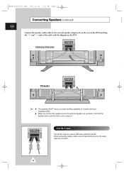
... on the PDP. When connecting cables, attach one of the cable with the diagram on the rear of the PDP matching the "+" and "-" ends of these ferrite cores to the cable near the connector. 20 Ferrite Cores The ferrite cores are used to secure it. PPM42S3/PPM50H3 PPM63H3 ➢ &#...9670; The speakers MUST have to a power handling capability of 10 watts minimum (impedance 8Ω). ◆ When you connect the speaker wire to the external speaker out connector, first bind the speaker ...
... on the PDP. When connecting cables, attach one of the cable with the diagram on the rear of the PDP matching the "+" and "-" ends of these ferrite cores to the cable near the connector. 20 Ferrite Cores The ferrite cores are used to secure it. PPM42S3/PPM50H3 PPM63H3 ➢ &#...9670; The speakers MUST have to a power handling capability of 10 watts minimum (impedance 8Ω). ◆ When you connect the speaker wire to the external speaker out connector, first bind the speaker ...

Owners Instructions
Page 38
...; œ √ œ Main √ Sel. Result: The options available in the following order: PIP Sel. Return You can monitor the video input from any connected devices while monitoring other video input. 1 Press the MENU button. BN68-00457B-01_ENG 2003.10.23 3:21 PM Page 38 Viewing the Picture In Picture...
...; œ √ œ Main √ Sel. Result: The options available in the following order: PIP Sel. Return You can monitor the video input from any connected devices while monitoring other video input. 1 Press the MENU button. BN68-00457B-01_ENG 2003.10.23 3:21 PM Page 38 Viewing the Picture In Picture...
Owners Instructions
Page 40
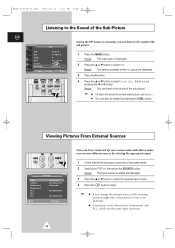
... Sound Sel.. Return 1 Press the MENU button. Set to Sub by selecting the appropriate input. 1 Check that all the necessary connections have connected up your PDP on, then press the SOURCE button. BN68-00457B-01_ENG 2003.10.23 3:21 PM Page 40 Listening to the ...PC2, which use the same input connector. 40 Viewing Pictures From External Sources AV Input Video S-Video Component1 Component2 PC1 PC2 DVI Connected Not Connected Connected Not Connected Not Connected Sel. PIP PIP Sel. Result: The options available in the PIP group are displayed. 3 Press the ▲ or ▼...
... Sound Sel.. Return 1 Press the MENU button. Set to Sub by selecting the appropriate input. 1 Check that all the necessary connections have connected up your PDP on, then press the SOURCE button. BN68-00457B-01_ENG 2003.10.23 3:21 PM Page 40 Listening to the ...PC2, which use the same input connector. 40 Viewing Pictures From External Sources AV Input Video S-Video Component1 Component2 PC1 PC2 DVI Connected Not Connected Connected Not Connected Not Connected Sel. PIP PIP Sel. Result: The options available in the PIP group are displayed. 3 Press the ▲ or ▼...
Owners Instructions
Page 41
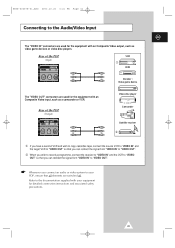
...player Camcorder Satellite receiver ② ① If you have a second VCR and wish to copy cassettes tape, connect the source VCR to "VIDEO IN" and the target VCR to "VIDEO OUT" so that you can redirect ...the signal from "VIDEO IN" to "VIDEO OUT". ② When you wish to record a programme, connect the receiver to "VIDEO IN" and the VCR to "VIDEO OUT" so that you can redirect the signal from...output, such as a camcorder or VCR. BN68-00457B-01_ENG 2003.10.23 3:21 PM Page 41 Connecting to the Audio/Video Input ENG The "VIDEO IN" connectors are used for the equipment with an ...
...player Camcorder Satellite receiver ② ① If you have a second VCR and wish to copy cassettes tape, connect the source VCR to "VIDEO IN" and the target VCR to "VIDEO OUT" so that you can redirect ...the signal from "VIDEO IN" to "VIDEO OUT". ② When you wish to record a programme, connect the receiver to "VIDEO IN" and the VCR to "VIDEO OUT" so that you can redirect the signal from...output, such as a camcorder or VCR. BN68-00457B-01_ENG 2003.10.23 3:21 PM Page 41 Connecting to the Audio/Video Input ENG The "VIDEO IN" connectors are used for the equipment with an ...
Owners Instructions
Page 42
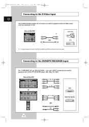
Rear of the PDP Y / Pb / Pr L / R DVD or Pr / Y / Pb Digital Set-Top Box and or 42 Connecting to the S-Video Input ENG The S-VIDEO and RCA (AUDIO-L/R) connectors are used for equipment with a DVD/ DTV RECEIVER output. (480i, 480p, 720, 1080i) Rear ... ① To play picture and sound, both the S-VIDEO and RCA connectors must be used. BN68-00457B-01_ENG 2003.10.23 3:21 PM Page 42 Connecting to the DVD/DTV RECEIVER Input The "COMPONENT1 IN" (or "R(Pr)/G(Y)/B(Pb)" (video) and "AUDIO") connectors are used for equipment with an S-Video output, such...
Rear of the PDP Y / Pb / Pr L / R DVD or Pr / Y / Pb Digital Set-Top Box and or 42 Connecting to the S-Video Input ENG The S-VIDEO and RCA (AUDIO-L/R) connectors are used for equipment with a DVD/ DTV RECEIVER output. (480i, 480p, 720, 1080i) Rear ... ① To play picture and sound, both the S-VIDEO and RCA connectors must be used. BN68-00457B-01_ENG 2003.10.23 3:21 PM Page 42 Connecting to the DVD/DTV RECEIVER Input The "COMPONENT1 IN" (or "R(Pr)/G(Y)/B(Pb)" (video) and "AUDIO") connectors are used for equipment with an S-Video output, such...

Owners Instructions
Page 43
BN68-00457B-01_ENG 2003.10.23 3:21 PM Page 43 Connecting to the RGB(PC) Input The "RGB1(PC1) IN" (or "R(Pr)/G(Y)/B(Pb)/H/V") and "AUDIO" connectors are used for equipment with your PC. Rear of the PDP Personal Computer and Connecting to the DVI Input ENG The "DVI IN" (video) and "AUDIO" connectors are used for interfacing with a DVI output. Rear of the PDP or Personal Computer 43
BN68-00457B-01_ENG 2003.10.23 3:21 PM Page 43 Connecting to the RGB(PC) Input The "RGB1(PC1) IN" (or "R(Pr)/G(Y)/B(Pb)/H/V") and "AUDIO" connectors are used for equipment with your PC. Rear of the PDP Personal Computer and Connecting to the DVI Input ENG The "DVI IN" (video) and "AUDIO" connectors are used for interfacing with a DVI output. Rear of the PDP or Personal Computer 43

Owners Instructions
Page 45
...+ 22 T.M.D.S. Clock+ 24 T.M.D.S. Data1- 10 T.M.D.S. Data5- 21 T.M.D.S. Data3+ 14 +5V Power 15 5V Grounding 16 Hot Plug Detect 17 T.M.D.S. Data4+ 6 Clock (DDC) 7 Data (DDC) 8 Not Connected 9 T.M.D.S.
...+ 22 T.M.D.S. Clock+ 24 T.M.D.S. Data1- 10 T.M.D.S. Data5- 21 T.M.D.S. Data3+ 14 +5V Power 15 5V Grounding 16 Hot Plug Detect 17 T.M.D.S. Data4+ 6 Clock (DDC) 7 Data (DDC) 8 Not Connected 9 T.M.D.S.
Owners Instructions
Page 48
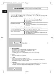
... but no sound No picture or black and white picture Sound and picture interference Remote control malfunctions ◆ Check that the mains lead has been connected to a warm place, unplug the power cord for at least two hours so that moisture that may have pressed the ON or OFF button. ◆... (transmission window). ◆ Check the battery terminals. BN68-00457B-01_ENG 2003.10.23 3:21 PM Page 48 Troubleshooting: Before Contacting Service Personnel ENG Before contacting Samsung after-sales service, perform the following simple checks. If you have formed inside . -
... but no sound No picture or black and white picture Sound and picture interference Remote control malfunctions ◆ Check that the mains lead has been connected to a warm place, unplug the power cord for at least two hours so that moisture that may have pressed the ON or OFF button. ◆... (transmission window). ◆ Check the battery terminals. BN68-00457B-01_ENG 2003.10.23 3:21 PM Page 48 Troubleshooting: Before Contacting Service Personnel ENG Before contacting Samsung after-sales service, perform the following simple checks. If you have formed inside . -


