Owners Instructions
Page 2
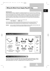
... or in PDP technology. Your new Samsung product represents the latest in part may void the user's authority to offer you of important instructions accompanying the product. Warning! REFER SERVICING TO QUALIFIED SERVICE PERSONNEL. Note to the wide slot, and fully insert the plug. Important: One Federal Court has held that unauthorized recording of copyrighted TV programs is provided...
... or in PDP technology. Your new Samsung product represents the latest in part may void the user's authority to offer you of important instructions accompanying the product. Warning! REFER SERVICING TO QUALIFIED SERVICE PERSONNEL. Note to the wide slot, and fully insert the plug. Important: One Federal Court has held that unauthorized recording of copyrighted TV programs is provided...
Owners Instructions
Page 4
... points or damage parts. If an outside antenna or cable system is connected to the PDP, be sure the antenna or cable system is grounded so as the original part. when the power-supply cord or plug is in a safe operating condition. ◆ The PDP can fall into the unit - Unauthorized substitutions may result in a temperature range of antenna discharge unit, connection to grounding electrodes...
... points or damage parts. If an outside antenna or cable system is connected to the PDP, be sure the antenna or cable system is grounded so as the original part. when the power-supply cord or plug is in a safe operating condition. ◆ The PDP can fall into the unit - Unauthorized substitutions may result in a temperature range of antenna discharge unit, connection to grounding electrodes...
Owners Instructions
Page 6
... FCC Rules. This Class B digital apparatus complies with Part 15 of the computer convenience outlet is available from that may cause undesired operation. 6 Install and use the equipment according to Identify and Resolve Radio/PDP Interference Problems helpful. If this monitor is used in a residential installation. Provided with IEC320 style terminations. If this is a detachable power supply cord with this equipment does...
... FCC Rules. This Class B digital apparatus complies with Part 15 of the computer convenience outlet is available from that may cause undesired operation. 6 Install and use the equipment according to Identify and Resolve Radio/PDP Interference Problems helpful. If this monitor is used in a residential installation. Provided with IEC320 style terminations. If this is a detachable power supply cord with this equipment does...
Owners Instructions
Page 9
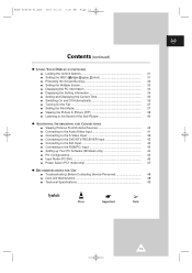
... BROWN or RED. If the fitted plug is indicated on this equipment is supplied with the letter N or coloured BLUE or BLACK. IMPORTANT The wires in the mains lead are available from the bared flexible cord. Checking Parts PPM42S3 & PPM50H3 Owner's Instructions Remote Control/ AAA Batteries Power Cord Speaker Wires (2EA) Stand-Base (2EA) 2 Install CD - Never use the plug with 3D noise reduction, detail enhancement, contrast enhancement and white enhancement...
... BROWN or RED. If the fitted plug is indicated on this equipment is supplied with the letter N or coloured BLUE or BLACK. IMPORTANT The wires in the mains lead are available from the bared flexible cord. Checking Parts PPM42S3 & PPM50H3 Owner's Instructions Remote Control/ AAA Batteries Power Cord Speaker Wires (2EA) Stand-Base (2EA) 2 Install CD - Never use the plug with 3D noise reduction, detail enhancement, contrast enhancement and white enhancement...
Owners Instructions
Page 10
... Warranty Information Regarding PDP Format Viewing 7 ■ User Instructions 8 ■ Wiring the Mains Power Supply Plug (UK Only 9 ◆ CONNECTING AND PREPARING YOUR DISPLAY ■ Your New Plasma Display Panel 12 ■ Becoming Familiar with the Remote Control 14 ■ Inserting the Batteries in the Remote Control 15 ■ Assembling the Stand-Base 15 ■ Installing the Display on the Wall Attachment Panel 16 ■ Installing the Display Vertically 18 ■ Before Using the Video Wall and the Multiple...
... Warranty Information Regarding PDP Format Viewing 7 ■ User Instructions 8 ■ Wiring the Mains Power Supply Plug (UK Only 9 ◆ CONNECTING AND PREPARING YOUR DISPLAY ■ Your New Plasma Display Panel 12 ■ Becoming Familiar with the Remote Control 14 ■ Inserting the Batteries in the Remote Control 15 ■ Assembling the Stand-Base 15 ■ Installing the Display on the Wall Attachment Panel 16 ■ Installing the Display Vertically 18 ■ Before Using the Video Wall and the Multiple...
Owners Instructions
Page 11
...; Setting and Displaying the Current Time 35 ■ Switching On and Off Automatically 36 ■ Turning On the Fan 37 ■ Setting the Film Mode 37 ■ Viewing the Picture In Picture (PIP 38 ■ Listening to the Sound of the Sub Picture 40 ◆ ADDITIONAL INFORMATION AND CONNECTIONS ■ Viewing Pictures From External Sources 40 ■ Connecting to the Audio/Video Input 41 ■ Connecting to the S-Video Input 42 ■ Connecting to the DVD/DTV RECEIVER Input...
...; Setting and Displaying the Current Time 35 ■ Switching On and Off Automatically 36 ■ Turning On the Fan 37 ■ Setting the Film Mode 37 ■ Viewing the Picture In Picture (PIP 38 ■ Listening to the Sound of the Sub Picture 40 ◆ ADDITIONAL INFORMATION AND CONNECTIONS ■ Viewing Pictures From External Sources 40 ■ Connecting to the Audio/Video Input 41 ■ Connecting to the S-Video Input 42 ■ Connecting to the DVD/DTV RECEIVER Input...
Owners Instructions
Page 12
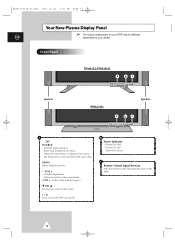
... settings in the menu. Volume adjustment. - b Power Indicator - Power On; Store your model. Power Off; Red - When the Main menu is displayed on the PDP. 12 Adjust an option value respectively. (VOL + : Enter to turn the PDP on and off. Timer On; Green c Remote Control Signal Receiver Aim the remote control towards this spot on screen, the Main menu is not operated with source key. VOL + - Off - External input selection. - MENU Menu display and exit. - I / Press to the selected menu.) ▼ SEL ▲ Control...
... settings in the menu. Volume adjustment. - b Power Indicator - Power On; Store your model. Power Off; Red - When the Main menu is displayed on the PDP. 12 Adjust an option value respectively. (VOL + : Enter to turn the PDP on and off. Timer On; Green c Remote Control Signal Receiver Aim the remote control towards this spot on screen, the Main menu is not operated with source key. VOL + - Off - External input selection. - MENU Menu display and exit. - I / Press to the selected menu.) ▼ SEL ▲ Control...
Owners Instructions
Page 13
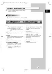
S-VIDEO). ENG Rear Panel ➢ For further details about connection, refer to output screen of Video or S-Video in PDP when connecting video and/or audio input of an Analog RGB or Y/Pb/Pr video signal from in PC, DVD, or HD devices. ➢ "PC Mode" from this page onward means PC1/PC2 mode using RGB1(PC1) and RGB2(PC2). b) DVI IN Connect to the video output jack for external devices with DVI output. f) VIDEO IN Video and audio inputs for...
S-VIDEO). ENG Rear Panel ➢ For further details about connection, refer to output screen of Video or S-Video in PDP when connecting video and/or audio input of an Analog RGB or Y/Pb/Pr video signal from in PC, DVD, or HD devices. ➢ "PC Mode" from this page onward means PC1/PC2 mode using RGB1(PC1) and RGB2(PC2). b) DVI IN Connect to the video output jack for external devices with DVI output. f) VIDEO IN Video and audio inputs for...
Owners Instructions
Page 14
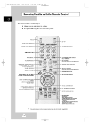
... the Remote Control ENG The remote control is used mainly to: ◆ Change sources and adjust the volume ◆ Set up the PDP using the on-screen menu system PDP ON SOUND MODE SELECTION PICTURE MODE SELECTION PDP OFF CURRENT TIME DISPLAY NUMERIC BUTTONS PICTURE STILL VOLUME INCREASE TEMPORARY SOUND SWITCH-OFF ➣ Press it again , or - /+ button to turn the sound back on. INPUT SOURCE SELECTION (SOURCE) - SIZE SELECTION (SIZE) - VOLUME DECREASE SETTING THE TIMER DISPLAY AND CLOSE THE MENU/ RETURN TO THE PREVIOUS MENU MOVE TO THE REQUIRED MENU OPTION/ ADJUST AN...
... the Remote Control ENG The remote control is used mainly to: ◆ Change sources and adjust the volume ◆ Set up the PDP using the on-screen menu system PDP ON SOUND MODE SELECTION PICTURE MODE SELECTION PDP OFF CURRENT TIME DISPLAY NUMERIC BUTTONS PICTURE STILL VOLUME INCREASE TEMPORARY SOUND SWITCH-OFF ➣ Press it again , or - /+ button to turn the sound back on. INPUT SOURCE SELECTION (SOURCE) - SIZE SELECTION (SIZE) - VOLUME DECREASE SETTING THE TIMER DISPLAY AND CLOSE THE MENU/ RETURN TO THE PREVIOUS MENU MOVE TO THE REQUIRED MENU OPTION/ ADJUST AN...
Owners Instructions
Page 16
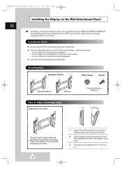
... proper installation guide for your model) PPM42S3/PPM50H3: 4 PPM63H3: 6 The wall mount bracket is for the following instructions.) 2 Set the angle by ±2°. Please tighten the captive screw in the direction of the arrow after assembling the bracket. 16 1 Secure the PDP to the wall mount bracket. (Please refer to bracket in an area subjected to Adjust Mounting Angle (depending on any heating apparatus. ◆ Use only recommended parts...
... proper installation guide for your model) PPM42S3/PPM50H3: 4 PPM63H3: 6 The wall mount bracket is for the following instructions.) 2 Set the angle by ±2°. Please tighten the captive screw in the direction of the arrow after assembling the bracket. 16 1 Secure the PDP to the wall mount bracket. (Please refer to bracket in an area subjected to Adjust Mounting Angle (depending on any heating apparatus. ◆ Use only recommended parts...
Owners Instructions
Page 18
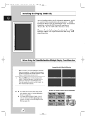
... remote control for Multiple Display Control connections 18 It may be difficult to put left side of the PDP on the remote control. You can install the PDP vertically. (PPM42S3/50H3/63H3 models are installed close to each PDP before installing them close together. Example for PDP adjustment. And you wish to stop the fan, position the PDP horizontally and then set "Selectable Fan" to "Setting the MDC (Multiple Display Control)" on the menu. Before Using the Video Wall...
... remote control for Multiple Display Control connections 18 It may be difficult to put left side of the PDP on the remote control. You can install the PDP vertically. (PPM42S3/50H3/63H3 models are installed close to each PDP before installing them close together. Example for PDP adjustment. And you wish to stop the fan, position the PDP horizontally and then set "Selectable Fan" to "Setting the MDC (Multiple Display Control)" on the menu. Before Using the Video Wall...
Owners Instructions
Page 30
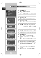
... displayed. Result: The Image Lock menu is displayed again. 11 Press the ▲ or ▼ button to select Reset. BN68-00457B-01_ENG 2003.10.23 3:21 PM Page 30 Adjusting the Image Preferences (PC Mode) ENG Setup Image Lock Key Lock Multi Control Burning Protection Video Wall Information √ œ Off Move Enter Return Image Lock Auto Adjustment Frequency Phase Position Zoom/Panning Move √ Enter Return Frequency 0 œ √ Adjust Return Position Adjust Store...
... displayed. Result: The Image Lock menu is displayed again. 11 Press the ▲ or ▼ button to select Reset. BN68-00457B-01_ENG 2003.10.23 3:21 PM Page 30 Adjusting the Image Preferences (PC Mode) ENG Setup Image Lock Key Lock Multi Control Burning Protection Video Wall Information √ œ Off Move Enter Return Image Lock Auto Adjustment Frequency Phase Position Zoom/Panning Move √ Enter Return Frequency 0 œ √ Adjust Return Position Adjust Store...
Owners Instructions
Page 31
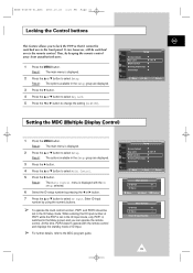
... switched to the Menu screen and you to change the setting (On or Off). Move œ √ Adjust Return Multi Control ID Setup 01 ID Input -- Setup Screen Adjust Key Lock Multi Control Burning Protection Video Wall √ œ Off Move Enter Return Multi Control ID Setup 01 ID Input -- Result: The Multi Control menu is displayed with the remote control and displays the standby mode of PDP1 while the PDP is set in the Setup group are displayed. 3 Press the √ button...
... switched to the Menu screen and you to change the setting (On or Off). Move œ √ Adjust Return Multi Control ID Setup 01 ID Input -- Setup Screen Adjust Key Lock Multi Control Burning Protection Video Wall √ œ Off Move Enter Return Multi Control ID Setup 01 ID Input -- Result: The Multi Control menu is displayed with the remote control and displays the standby mode of PDP1 while the PDP is set in the Setup group are displayed. 3 Press the √ button...
Owners Instructions
Page 32
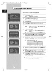
...; button to select Setup. Result: The Burning Protection menu is displayed with the Set selected. ➣ You can prevent the residual image of the PDP. Return 6 Press the √ button again. Set to On by pressing the œ or √ button for making the screen white. ➣ The Signal Pattern and All White feature are effective after working for pixel shift; Set to select All White. Setup Screen Adjust Key Lock Multi Control Burning Protection Video Wall...
...; button to select Setup. Result: The Burning Protection menu is displayed with the Set selected. ➣ You can prevent the residual image of the PDP. Return 6 Press the √ button again. Set to On by pressing the œ or √ button for making the screen white. ➣ The Signal Pattern and All White feature are effective after working for pixel shift; Set to select All White. Setup Screen Adjust Key Lock Multi Control Burning Protection Video Wall...
Owners Instructions
Page 40
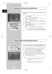
...; or ▼ button to select Sound Sel.. Swap Size Locate Sound Sel. Viewing Pictures From External Sources AV Input Video S-Video Component1 Component2 PC1 PC2 DVI Connected Not Connected Connected Not Connected Not Connected Sel. Store Once you have been made. 2 Switch your various audio and video systems, you change the external source while viewing, pictures might take a short period of time to be switched. ◆ Connection is not indicated for Component2 and PC2, which use the same input connector. 40 BN68...
...; or ▼ button to select Sound Sel.. Swap Size Locate Sound Sel. Viewing Pictures From External Sources AV Input Video S-Video Component1 Component2 PC1 PC2 DVI Connected Not Connected Connected Not Connected Not Connected Sel. Store Once you have been made. 2 Switch your various audio and video systems, you change the external source while viewing, pictures might take a short period of time to be switched. ◆ Connection is not indicated for Component2 and PC2, which use the same input connector. 40 BN68...
Owners Instructions
Page 41
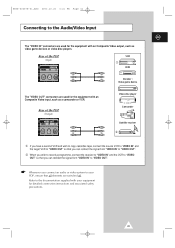
... the signal from "VIDEO IN" to "VIDEO OUT". ② When you wish to record a programme, connect the receiver to "VIDEO IN" and the VCR to "VIDEO OUT" so that all elements are used for the equipment with an Composite Video output, such as a camcorder or VCR. Refer to the Audio/Video Input ENG The "VIDEO IN" connectors are switched off. Rear of the PDP (Input) VCR ① DVD Decoder / Video game...
... the signal from "VIDEO IN" to "VIDEO OUT". ② When you wish to record a programme, connect the receiver to "VIDEO IN" and the VCR to "VIDEO OUT" so that all elements are used for the equipment with an Composite Video output, such as a camcorder or VCR. Refer to the Audio/Video Input ENG The "VIDEO IN" connectors are switched off. Rear of the PDP (Input) VCR ① DVD Decoder / Video game...
Owners Instructions
Page 42
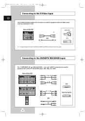
... used . Rear of the PDP Y / Pb / Pr L / R DVD or Pr / Y / Pb Digital Set-Top Box and or 42 BN68-00457B-01_ENG 2003.10.23 3:21 PM Page 42 Connecting to the DVD/DTV RECEIVER Input The "COMPONENT1 IN" (or "R(Pr)/G(Y)/B(Pb)" (video) and "AUDIO") connectors are used for equipment with a DVD/ DTV RECEIVER output. (480i, 480p, 720, 1080i) Rear of the PDP Camcorder ① and VCR ① To play picture and sound...
... used . Rear of the PDP Y / Pb / Pr L / R DVD or Pr / Y / Pb Digital Set-Top Box and or 42 BN68-00457B-01_ENG 2003.10.23 3:21 PM Page 42 Connecting to the DVD/DTV RECEIVER Input The "COMPONENT1 IN" (or "R(Pr)/G(Y)/B(Pb)" (video) and "AUDIO") connectors are used for equipment with a DVD/ DTV RECEIVER output. (480i, 480p, 720, 1080i) Rear of the PDP Camcorder ① and VCR ① To play picture and sound...
Owners Instructions
Page 47
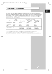
... your monitor OFF when it is not needed, or when leaving it has not been used for a certain amount of time. This power management system operates with a VESA DPMS compliant video card installed in power management system called Power Saver. This power management system saves energy by switching your computer. You use a software utility installed on the keyboard. ◆ For energy conservation, turn your computer to set up...
... your monitor OFF when it is not needed, or when leaving it has not been used for a certain amount of time. This power management system operates with a VESA DPMS compliant video card installed in power management system called Power Saver. This power management system saves energy by switching your computer. You use a software utility installed on the keyboard. ◆ For energy conservation, turn your computer to set up...
Owners Instructions
Page 48
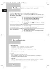
... the picture contrast and brightness settings. ◆ Check the volume. ◆ Check the volume. ◆ Check whether the volume MUTE button on the remote control has been pressed. ◆ Adjust the color settings. ◆ Check that the video system selected is suddenly moved from a cold to a wall socket. ◆ Check that create magnetic fields. - Wipe your PDP into a different mains socket. ◆ Replace the remote control batteries...
... the picture contrast and brightness settings. ◆ Check the volume. ◆ Check the volume. ◆ Check whether the volume MUTE button on the remote control has been pressed. ◆ Adjust the color settings. ◆ Check that the video system selected is suddenly moved from a cold to a wall socket. ◆ Check that create magnetic fields. - Wipe your PDP into a different mains socket. ◆ Replace the remote control batteries...
User Guide
Page 4
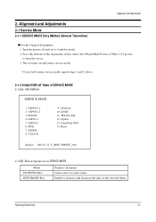
... Adjustments 2-1 Service Mode 2-1-1 SERVICE MODE Entry Method (General Transmitter) s For the General Transmitter 1. CheckSum 0000 14. Turn the power off and set to enter service mode, repeat steps 1 and 2 above. 2-1-2 Initial DISPLAY State of SERVICE MODE 2-1-2(A) OSD DISPLAY SERVICE MAIN 1. VSP9437-1 2. CXA2151 9. CXA2101 10. ASI500-2 6. TP LOG-ASI 12. ASI500-1 5. Press the buttons of the selected items Samsung Electronics 2-1 The set on and enters service mode. * If you fail to stand...
... Adjustments 2-1 Service Mode 2-1-1 SERVICE MODE Entry Method (General Transmitter) s For the General Transmitter 1. CheckSum 0000 14. Turn the power off and set to enter service mode, repeat steps 1 and 2 above. 2-1-2 Initial DISPLAY State of SERVICE MODE 2-1-2(A) OSD DISPLAY SERVICE MAIN 1. VSP9437-1 2. CXA2151 9. CXA2101 10. ASI500-2 6. TP LOG-ASI 12. ASI500-1 5. Press the buttons of the selected items Samsung Electronics 2-1 The set on and enters service mode. * If you fail to stand...


