
Owners Instructions
Page 1
Intended for future reference. PDP-MONITOR (PLASMA DISPLAY PANEL) Owner's Instructions Before operating the unit, please read this manual thoroughly, and retain it for Commercial Use and Operation ON-SCREEN MENUS PICTURE IN PICTURE (PIP) VIDEO WALL MDC (MULTIPLE DISPLAY CONTROL)
Intended for future reference. PDP-MONITOR (PLASMA DISPLAY PANEL) Owner's Instructions Before operating the unit, please read this manual thoroughly, and retain it for Commercial Use and Operation ON-SCREEN MENUS PICTURE IN PICTURE (PIP) VIDEO WALL MDC (MULTIPLE DISPLAY CONTROL)

Owners Instructions
Page 2
...total PDP viewing per week. Thank you a product that offer picture sizing features, use these controls to fill the screen if your Samsung limited warranty. We designed it with 3D noise reduction, detail enhancement, contrast enhancement and white enhancement. The images displayed on screen,...web sites or computer graphics and patterns, should primarily be limited to view wide screen format full-motion video. Your new Samsung product represents the latest in the PDP picture. Important Warranty Information Regarding PDP Format Viewing Wide screen format PDP Displays (...
...total PDP viewing per week. Thank you a product that offer picture sizing features, use these controls to fill the screen if your Samsung limited warranty. We designed it with 3D noise reduction, detail enhancement, contrast enhancement and white enhancement. The images displayed on screen,...web sites or computer graphics and patterns, should primarily be limited to view wide screen format full-motion video. Your new Samsung product represents the latest in the PDP picture. Important Warranty Information Regarding PDP Format Viewing Wide screen format PDP Displays (...

Owners Instructions
Page 3
... Wires (2EA) Stand-Base (2EA) 1 Install CD MDC Software (RS232C) Ferrite Cores for Speaker Wire (2EA) PC Cable MDC Cable (RS232C) Screws (4EA) ➢ The PPM42H3 model uses the same MDC program CD used for more than 2 hours as "screen burn". Although the panels are produced with more than 99.9 percent...
... Wires (2EA) Stand-Base (2EA) 1 Install CD MDC Software (RS232C) Ferrite Cores for Speaker Wire (2EA) PC Cable MDC Cable (RS232C) Screws (4EA) ➢ The PPM42H3 model uses the same MDC program CD used for more than 2 hours as "screen burn". Although the panels are produced with more than 99.9 percent...

Owners Instructions
Page 4
Auto Volume - ENG Contents ◆ FOREWORD ■ Important Warranty Information Regarding PDP Format Viewing 2 ■ User Instructions 3 ◆ CONNECTING AND PREPARING YOUR DISPLAY ■ Your New Plasma Display Panel 6 ■ Becoming Familiar with the Remote Control 8 ■ Inserting the Batteries in the Remote Control 9 ■ Assembling the Stand-Base 9 ■ Installing the Display on the Wall Attachment Panel 10 ■ Before Using the Video Wall and the Multiple Display Contol function ......... 12 ■ Connecting Speakers 13 ■...
Auto Volume - ENG Contents ◆ FOREWORD ■ Important Warranty Information Regarding PDP Format Viewing 2 ■ User Instructions 3 ◆ CONNECTING AND PREPARING YOUR DISPLAY ■ Your New Plasma Display Panel 6 ■ Becoming Familiar with the Remote Control 8 ■ Inserting the Batteries in the Remote Control 9 ■ Assembling the Stand-Base 9 ■ Installing the Display on the Wall Attachment Panel 10 ■ Before Using the Video Wall and the Multiple Display Contol function ......... 12 ■ Connecting Speakers 13 ■...
Owners Instructions
Page 5
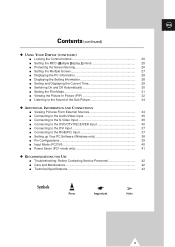
ENG Contents (continued) ◆ USING YOUR DISPLAY (CONTINUED) ■ Locking the Control buttons 25 ■ Setting the MDC (Multiple Display Control 25 ■ Protecting the Screen Burning 26 ■ Setting the Multiple Screen 27 ■ Displaying the PC Information 28 ■ Displaying the Setting Information 28 ■ Setting and Displaying the Current Time 29 ■ Switching On and Off Automatically 30 ■ Setting the Film Mode 31 ■ Viewing the Picture In Picture (PIP 32 ■ Listening to the Sound of the Sub Picture 34 ◆ ADDITIONAL INFORMATION AND ...
ENG Contents (continued) ◆ USING YOUR DISPLAY (CONTINUED) ■ Locking the Control buttons 25 ■ Setting the MDC (Multiple Display Control 25 ■ Protecting the Screen Burning 26 ■ Setting the Multiple Screen 27 ■ Displaying the PC Information 28 ■ Displaying the Setting Information 28 ■ Setting and Displaying the Current Time 29 ■ Switching On and Off Automatically 30 ■ Setting the Film Mode 31 ■ Viewing the Picture In Picture (PIP 32 ■ Listening to the Sound of the Sub Picture 34 ◆ ADDITIONAL INFORMATION AND ...

Owners Instructions
Page 6
Store your settings in the menu. Adjust an option value respectively. (VOL + : Enter to turn the PDP on and off. Power Off; When the Main menu is not operated with source key. Power On; Your New Plasma Display Panel ENG Front Panel a bc Speaker Speaker a SOURCE - VOL + - Timer On; Red - Green c Remote Control Signal Receiver Aim the remote control towards this spot on screen, the Main menu is displayed on the PDP. 6 External input selection. - b Power Indicator - I / Press to the selected menu.) ▼ SEL ▲ Control the cursor in the menu. - ...
Store your settings in the menu. Adjust an option value respectively. (VOL + : Enter to turn the PDP on and off. Power Off; When the Main menu is not operated with source key. Power On; Your New Plasma Display Panel ENG Front Panel a bc Speaker Speaker a SOURCE - VOL + - Timer On; Red - Green c Remote Control Signal Receiver Aim the remote control towards this spot on screen, the Main menu is displayed on the PDP. 6 External input selection. - b Power Indicator - I / Press to the selected menu.) ▼ SEL ▲ Control the cursor in the menu. - ...

Owners Instructions
Page 7
a b cd e f g h i j a) RS232C - c) AUDIO Connect to the audio output jack on your PC or any device with DVI output. (It is audio input for external devices with an S-Video output; h) VIDEO OUT (VIDEO / L-AUDIO-R) Used to the video output jack on your PC. f) VIDEO IN Video and audio inputs for external devices, such as VCR, DVD, video game device or video disc players (or for b, d, and e.) d) RGB1(PC1) IN Connect to output screen of another PDP. - S-VIDEO). j) POWER IN Connect the supplied power cord. 7 e) COMPONENT2/RGB2(PC2) IN Connect for device with RS232C ...
a b cd e f g h i j a) RS232C - c) AUDIO Connect to the audio output jack on your PC or any device with DVI output. (It is audio input for external devices with an S-Video output; h) VIDEO OUT (VIDEO / L-AUDIO-R) Used to the video output jack on your PC. f) VIDEO IN Video and audio inputs for external devices, such as VCR, DVD, video game device or video disc players (or for b, d, and e.) d) RGB1(PC1) IN Connect to output screen of another PDP. - S-VIDEO). j) POWER IN Connect the supplied power cord. 7 e) COMPONENT2/RGB2(PC2) IN Connect for device with RS232C ...

Owners Instructions
Page 8
LOCATION SELECTION (LOCATE) - INPUT SOURCE SELECTION (SOURCE) - INTERCHANGE THE MAIN AND THE SUB PICTURE (SWAP) - SOUND SELECTION (S.SEL) ➢ The performance of the remote control may be affected by bright light. 8 PIP ON/OFF - VOLUME DECREASE SETTING THE TIMER DISPLAY AND CLOSE THE MENU/ RETURN TO THE PREVIOUS MENU ZOOM/PANNING MENU DISPLAY (ONLY PC MODE) NEXT CHANNEL (NOT AVAILABLE FOR THIS MONITOR) EXTERNAL INPUT SELECTION PREVIOUS CHANNEL (NOT AVAILABLE FOR THIS MONITOR) INFORMATION DISPLAY EXIT FROM ANY DISPLAY MOVE TO THE REQUIRED MENU OPTION/ ADJUST AN OPTION VALUE ...
LOCATION SELECTION (LOCATE) - INPUT SOURCE SELECTION (SOURCE) - INTERCHANGE THE MAIN AND THE SUB PICTURE (SWAP) - SOUND SELECTION (S.SEL) ➢ The performance of the remote control may be affected by bright light. 8 PIP ON/OFF - VOLUME DECREASE SETTING THE TIMER DISPLAY AND CLOSE THE MENU/ RETURN TO THE PREVIOUS MENU ZOOM/PANNING MENU DISPLAY (ONLY PC MODE) NEXT CHANNEL (NOT AVAILABLE FOR THIS MONITOR) EXTERNAL INPUT SELECTION PREVIOUS CHANNEL (NOT AVAILABLE FOR THIS MONITOR) INFORMATION DISPLAY EXIT FROM ANY DISPLAY MOVE TO THE REQUIRED MENU OPTION/ ADJUST AN OPTION VALUE ...

Owners Instructions
Page 9
Assembling the Stand-Base Fit the Stand-Base into place. Never lay the PDP on the floor because of possible damage to remove it back into the guide hole on the bottom of the monitor and tighten the left and right sides using four screws for each side. ➢ Two or more people should carry the PDP. Always store the PDP upright. 9 on the remote control ◆ + on the battery against - Inserting the Batteries in the Remote Control ENG You must insert or replace the batteries in the remote control when you: ◆ Purchase the PDP ◆ Find that the remote control is no longer ...
Assembling the Stand-Base Fit the Stand-Base into place. Never lay the PDP on the floor because of possible damage to remove it back into the guide hole on the bottom of the monitor and tighten the left and right sides using four screws for each side. ➢ Two or more people should carry the PDP. Always store the PDP upright. 9 on the remote control ◆ + on the battery against - Inserting the Batteries in the Remote Control ENG You must insert or replace the batteries in the remote control when you: ◆ Purchase the PDP ◆ Find that the remote control is no longer ...

Owners Instructions
Page 10
Do not install near or around any place other than vertical walls. ◆ To protect the performance of the arrow. 3 The angle can be different from 0° to 20° by pulling the upper end of the PDP attached to the following instructions.) 2 Set the angle by ±2°. Installation Notes ◆ Do not install the PDP on the Wall Attachment Panel ENG ☛ This wall mount bracket installation guide is delivered separately. Do not install in the direction of the arrow after assembling the bracket. 10 1 Secure the PDP to the wall mount bracket. (Please refer to ...
Do not install near or around any place other than vertical walls. ◆ To protect the performance of the arrow. 3 The angle can be different from 0° to 20° by pulling the upper end of the PDP attached to the following instructions.) 2 Set the angle by ±2°. Installation Notes ◆ Do not install the PDP on the Wall Attachment Panel ENG ☛ This wall mount bracket installation guide is delivered separately. Do not install in the direction of the arrow after assembling the bracket. 10 1 Secure the PDP to the wall mount bracket. (Please refer to ...
Owners Instructions
Page 11
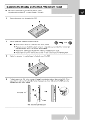
Installing the Display on the PDP (!) to secure it to install the wall mount bracket. ◆ Please be separated from the back of the PDP. 2 Use the screws and assemble the plastic hanger. ☛ ◆ Please ask the installers to the wall mount bracket (@). Tighten the screws as shown (#) so that the PDP cannot be sure to check if the plastic hanger is completely secured on both the left and right side after hanging the PDP on the wall mount bracket. ◆ Please avoid catching your fingers while installing and adjusting the angle. ◆ Please tightly secure the wall mount ...
Installing the Display on the PDP (!) to secure it to install the wall mount bracket. ◆ Please be separated from the back of the PDP. 2 Use the screws and assemble the plastic hanger. ☛ ◆ Please ask the installers to the wall mount bracket (@). Tighten the screws as shown (#) so that the PDP cannot be sure to check if the plastic hanger is completely secured on both the left and right side after hanging the PDP on the wall mount bracket. ◆ Please avoid catching your fingers while installing and adjusting the angle. ◆ Please tightly secure the wall mount ...

Owners Instructions
Page 12
... control for the PDP that are installed close together. Select ID input on page 25 and the Help section in MDC program CD. ◆ The PPM42H3 model uses the same MDC program CD used for Multiple Display Control connections 12 Example for PPM50H3/PPM63H3 models. ➢ Do not install the PDP...
... control for the PDP that are installed close together. Select ID input on page 25 and the Help section in MDC program CD. ◆ The PPM42H3 model uses the same MDC program CD used for Multiple Display Control connections 12 Example for PPM50H3/PPM63H3 models. ➢ Do not install the PDP...

Owners Instructions
Page 13
It may damage the bracket clamping the speaker and your PDP together and result in a drop of personal damage and injury. 13 Connecting Speakers ENG 1 Remove the screws on the rear of the PDP. 2 Hang the two "T" shaped hangers on the square holes on the rear of the PDP. 3 Tighten the PDP and the speaker bracket using the screws removed from the PDP. ➢ When moving your PDP, do NOT hold the speaker connected to your PDP and a risk of your PDP.
It may damage the bracket clamping the speaker and your PDP together and result in a drop of personal damage and injury. 13 Connecting Speakers ENG 1 Remove the screws on the rear of the PDP. 2 Hang the two "T" shaped hangers on the square holes on the rear of the PDP. 3 Tighten the PDP and the speaker bracket using the screws removed from the PDP. ➢ When moving your PDP, do NOT hold the speaker connected to your PDP and a risk of your PDP.

Owners Instructions
Page 14
Ferrite Cores The ferrite cores are used to the cable near the connector. 14 When connecting cables, attach one of 10 watts minimum (impedance 8Ω). ◆ When you connect the speaker wire to the external speaker out connector, first bind the speaker wire round the ferrite core to secure it. Connecting Speakers (continued) ENG Connect the speaker audio cable to the external speaker output jack on the rear of the PDP matching the "+" and "-" ends of the cable with the diagram on the PDP. ➢ ◆ The speakers MUST have to a power handling capability of these ferrite cores ...
Ferrite Cores The ferrite cores are used to the cable near the connector. 14 When connecting cables, attach one of 10 watts minimum (impedance 8Ω). ◆ When you connect the speaker wire to the external speaker out connector, first bind the speaker wire round the ferrite core to secure it. Connecting Speakers (continued) ENG Connect the speaker audio cable to the external speaker output jack on the rear of the PDP matching the "+" and "-" ends of the cable with the diagram on the PDP. ➢ ◆ The speakers MUST have to a power handling capability of these ferrite cores ...

Owners Instructions
Page 15
Result: The Standby indicator on the front of the PDP and the frequency is selected. 4 Press the √ button again. Result: The Language option is 50 or 60Hz. 2 Press the " I / " button on the front of the PDP (or ON ( ) button on the remote control) to switch the PDP on. 3 To switch your choice. Store 15 Result: The options available in the Function group are listed. 5 Select the appropriate language by pressing the ▲ or ▼ button repeatedly. 6 Press the button to confirm your PDP off, press the " I / " button again (or OFF button on the rear of the PDP lights...
Result: The Standby indicator on the front of the PDP and the frequency is selected. 4 Press the √ button again. Result: The Language option is 50 or 60Hz. 2 Press the " I / " button on the front of the PDP (or ON ( ) button on the remote control) to switch the PDP on. 3 To switch your choice. Store 15 Result: The options available in the Function group are listed. 5 Select the appropriate language by pressing the ▲ or ▼ button repeatedly. 6 Press the button to confirm your PDP off, press the " I / " button again (or OFF button on the rear of the PDP lights...

Owners Instructions
Page 16
Selecting the Color System (Video or S-Video Mode) ➢ Preset to select Mode. Select the option by pressing the œ or √ button. Movie - Custom ◆ Custom - AUTO - Result: The options available in the Picture group are available. High - Result: The Color System is selected. 3 Select a required color system by pressing the œ or √ button. PAL - PAL60 Changing the Picture Mode Mode Adjust Color Tone Size Digital NR Picture œ Dynamic √ √ œ Normal √ Wide œ Off √ Move Sel. Color System Mode ...
Selecting the Color System (Video or S-Video Mode) ➢ Preset to select Mode. Select the option by pressing the œ or √ button. Movie - Custom ◆ Custom - AUTO - Result: The options available in the Picture group are available. High - Result: The Color System is selected. 3 Select a required color system by pressing the œ or √ button. PAL - PAL60 Changing the Picture Mode Mode Adjust Color Tone Size Digital NR Picture œ Dynamic √ √ œ Normal √ Wide œ Off √ Move Sel. Color System Mode ...

Owners Instructions
Page 17
Press the œ or √ button. Result: The options available in the Picture group are displayed in the Picture group are satisfied with the settings, press the store them. Warm1 - Cool1 ➣ If you make any changes to these settings, the picture mode is automatically switched to control picture quality. 1 Press the MENU button. The color tones are displayed again. 7 Press the ▲ or ▼ button to select Adjust. Warm2 - Select the option by pressing the œ or √ button. 5 When you are displayed. 2 Press the √ button. 3 Press the &#...
Press the œ or √ button. Result: The options available in the Picture group are displayed in the Picture group are satisfied with the settings, press the store them. Warm1 - Cool1 ➣ If you make any changes to these settings, the picture mode is automatically switched to control picture quality. 1 Press the MENU button. The color tones are displayed again. 7 Press the ▲ or ▼ button to select Adjust. Warm2 - Select the option by pressing the œ or √ button. 5 When you are displayed. 2 Press the √ button. 3 Press the &#...

Owners Instructions
Page 18
button to 18 Press the √ button. Press the œ or √ button. button to 6 Press the MENU button. Adjusting the Picture Settings (PC or DVI Mode) ➢ Preset to be adjusted. Return Picture Mode Adjust Color Tone Color Adjust Size œ Custom √ √ œ Custom √ √ Wide Move Enter Return Color Adjust Red Green Blue Move Adjust 50 50 50 Store 1 Press the MENU button. Result: The Adjust menu is displayed. ◆ The Color Adjust menu can not be adjusted. Result: The horizontal bar is displayed. Result: The options available ...
button to 18 Press the √ button. Press the œ or √ button. button to 6 Press the MENU button. Adjusting the Picture Settings (PC or DVI Mode) ➢ Preset to be adjusted. Return Picture Mode Adjust Color Tone Color Adjust Size œ Custom √ √ œ Custom √ √ Wide Move Enter Return Color Adjust Red Green Blue Move Adjust 50 50 50 Store 1 Press the MENU button. Result: The Adjust menu is displayed. ◆ The Color Adjust menu can not be adjusted. Result: The horizontal bar is displayed. Result: The options available ...

Owners Instructions
Page 19
Zoom2 - 14:9 - Mode Adjust Color Tone Size Digital NR Picture œ Dynamic √ √ œ Normal √ Wide œ Off √ Move Sel. Selecting the Picture Size You can activate this feature to reduce any static and ghosting that may appear on the input source. ◆ Wide - Size Wide Store ENG Activating/Deactivating the Digital Noise Reduction Feature If the signal received by pressing the † or ... Return œ √ Sel. Result: The options available in the Picture group are displayed. 2 Press the √ button. 3 Press the ▲ or &#...
Zoom2 - 14:9 - Mode Adjust Color Tone Size Digital NR Picture œ Dynamic √ √ œ Normal √ Wide œ Off √ Move Sel. Selecting the Picture Size You can activate this feature to reduce any static and ghosting that may appear on the input source. ◆ Wide - Size Wide Store ENG Activating/Deactivating the Digital Noise Reduction Feature If the signal received by pressing the † or ... Return œ √ Sel. Result: The options available in the Picture group are displayed. 2 Press the √ button. 3 Press the ▲ or &#...

Owners Instructions
Page 20
Result: The Mode is displayed. 2 Press the ▲ or ▼ button to select Sound. Result: The main menu is selected. 4 Select the option by pressing the œ or √ button. Standard - Return You can also set these options simply by pressing the "STILL" button. Custom - Movie - To return to be used when watching a given broadcast. 1 Press the MENU button. Result: The options available in the following order. Changing the Sound Mode Sound Mode Equalizer Auto Volume Melody Pseudo Stereo Virtual Surround œ Custom √ √ œ Off √ &#...
Result: The Mode is displayed. 2 Press the ▲ or ▼ button to select Sound. Result: The main menu is selected. 4 Select the option by pressing the œ or √ button. Standard - Return You can also set these options simply by pressing the "STILL" button. Custom - Movie - To return to be used when watching a given broadcast. 1 Press the MENU button. Result: The options available in the following order. Changing the Sound Mode Sound Mode Equalizer Auto Volume Melody Pseudo Stereo Virtual Surround œ Custom √ √ œ Off √ &#...