
User Guide
Page 1
Adjustment Item Menu Guide: TCRU Model Name: Pro C900S/Pro C900 Read this manual carefully before using this machine and keep it handy for future reference. 1
Adjustment Item Menu Guide: TCRU Model Name: Pro C900S/Pro C900 Read this manual carefully before using this machine and keep it handy for future reference. 1
User Guide
Page 3
Trademark: • Acrobat® is a registered trademark of Adobe Systems Incorporated. • EFI, Fiery and Fiery Driven are used on or near switches on machines for Europe and other areas, the meaning of data, and to prevent damage to avoid misfeeds and loss...important information that might not be available in this information to the machine and originals. • The manufacturer shall not be slightly different from use of Electronics for any damage or expense that you must read: RWARNING Failure to ensure safe operation and avoid minor injuries. in serious injury or...
Trademark: • Acrobat® is a registered trademark of Adobe Systems Incorporated. • EFI, Fiery and Fiery Driven are used on or near switches on machines for Europe and other areas, the meaning of data, and to prevent damage to avoid misfeeds and loss...important information that might not be available in this information to the machine and originals. • The manufacturer shall not be slightly different from use of Electronics for any damage or expense that you must read: RWARNING Failure to ensure safe operation and avoid minor injuries. in serious injury or...
User Guide
Page 4
... supply. A frayed or otherwise damaged power cord can result in fire. 5. Clean it is grounded (earthed) at the wall outlet using the ground wire on the plug, not the cable. 3 Never use an extension cord. 8. Power Plug and Power Cord 1. Make sure that can cause a short circuit which could lead to build...
... supply. A frayed or otherwise damaged power cord can result in fire. 5. Clean it is grounded (earthed) at the wall outlet using the ground wire on the plug, not the cable. 3 Never use an extension cord. 8. Power Plug and Power Cord 1. Make sure that can cause a short circuit which could lead to build...
User Guide
Page 5
...reasons, do not dispose of the machine or expended supply waste at an authorized dealer. • The inside the machine. • Keep toner (used toner is not damaged under the machine. • When disconnecting the power plug from humidity and dust. If your skin comes into eyes, wash... are non-toxic supplies.) 3. If it topples over, an injury might make sure there is a continuous air turnover. • If toner or used toner gets into contact with toner, wash the affected area thoroughly with plenty of this machine gets very hot. While moving the machine. Disposal can...
...reasons, do not dispose of the machine or expended supply waste at an authorized dealer. • The inside the machine. • Keep toner (used toner is not damaged under the machine. • When disconnecting the power plug from humidity and dust. If your skin comes into eyes, wash... are non-toxic supplies.) 3. If it topples over, an injury might make sure there is a continuous air turnover. • If toner or used toner gets into contact with toner, wash the affected area thoroughly with plenty of this machine gets very hot. While moving the machine. Disposal can...
User Guide
Page 6
... ROLLER UNIT 46 8.1 REMOVING THE PAPER TRANSFER ROLLER UNIT 46 8.2 INSTALLING THE PAPER TRANSFER ROLLER UNIT 48 5 Table of Contents CONVENTIONS USED IN THIS MANUAL 2 GENERAL SAFETY INSTRUCTIONS 2 1. CHARGE CORONA UNIT 17 3.1 REMOVING THE CHARGE CORONA UNIT 17 3.2 REINSTALLING THE CHARGE... CORONA UNIT 20 4. DEVELOPER 33 6.1 REMOVING THE USED DEVELOPER 33 6.2 ADDING NEW DEVELOPER 38 7. IMAGE TRANSFER BELT CLEANING UNIT 41 7.1 REMOVING THE IMAGE TRANSFER BELT CLEANING UNIT 41 7.2 ...
... ROLLER UNIT 46 8.1 REMOVING THE PAPER TRANSFER ROLLER UNIT 46 8.2 INSTALLING THE PAPER TRANSFER ROLLER UNIT 48 5 Table of Contents CONVENTIONS USED IN THIS MANUAL 2 GENERAL SAFETY INSTRUCTIONS 2 1. CHARGE CORONA UNIT 17 3.1 REMOVING THE CHARGE CORONA UNIT 17 3.2 REINSTALLING THE CHARGE... CORONA UNIT 20 4. DEVELOPER 33 6.1 REMOVING THE USED DEVELOPER 33 6.2 ADDING NEW DEVELOPER 38 7. IMAGE TRANSFER BELT CLEANING UNIT 41 7.1 REMOVING THE IMAGE TRANSFER BELT CLEANING UNIT 41 7.2 ...
User Guide
Page 7
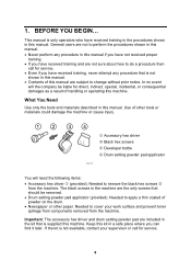
... accessory hex driver and drum setting powder pad are included in the machine are the only screws that is supplied this manual. What You Need Use only the tools and materials described in this manual. • Contents of handling or operating this manual are not sure about how to do a procedure...). Keep this kit in this machine. This manual is not available, contact your work surface and prevent toner spillage from components removed from the machine. 1. Use of powder on the drum. • Newspaper or other tools or materials could damage the machine or cause injury.
... accessory hex driver and drum setting powder pad are included in the machine are the only screws that is supplied this manual. What You Need Use only the tools and materials described in this manual. • Contents of handling or operating this manual are not sure about how to do a procedure...). Keep this kit in this machine. This manual is not available, contact your work surface and prevent toner spillage from components removed from the machine. 1. Use of powder on the drum. • Newspaper or other tools or materials could damage the machine or cause injury.
User Guide
Page 11
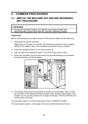
... and fixing heater. Shut down . RPG069 5. The fusing unit becomes extremely hot during normal operation. 2. The operation switch is in this manual, always do not use the machine for your machine. 2. Press the operation switch to cool down the printer controller. COMMON PROCEDURES 2.1 SWITCH THE MACHINE OFF BEFORE BEGINNING ANY PROCEDURE...
... and fixing heater. Shut down . RPG069 5. The fusing unit becomes extremely hot during normal operation. 2. The operation switch is in this manual, always do not use the machine for your machine. 2. Press the operation switch to cool down the printer controller. COMMON PROCEDURES 2.1 SWITCH THE MACHINE OFF BEFORE BEGINNING ANY PROCEDURE...
User Guide
Page 12
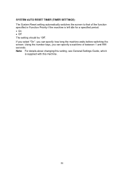
SYSTEM AUTO RESET TIMER (TIMER SETTINGS) The System Reset setting automatically switches the screen to that of between 1 and 999 seconds. If you select "On", you can specify how long the machine waits before switching the screen. Note: For details about changing this machine. 11 Using the number keys, you can specify a wait time of the function specified in Function Priority if the machine is supplied with this setting, see General Settings Guide, which is left idle for a specified period. • On • Off The setting should be "Off".
SYSTEM AUTO RESET TIMER (TIMER SETTINGS) The System Reset setting automatically switches the screen to that of between 1 and 999 seconds. If you select "On", you can specify how long the machine waits before switching the screen. Note: For details about changing this machine. 11 Using the number keys, you can specify a wait time of the function specified in Function Priority if the machine is supplied with this setting, see General Settings Guide, which is left idle for a specified period. • On • Off The setting should be "Off".
User Guide
Page 13
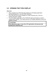
This means that the LCD display application cannot be installed on TCRU machines only. It will permanently disable the TCRU SD card. 12 RCAUTION Any attempt to copy or move the LCD application will not function with TCRU machines. • The TCRU SD card can be copied or moved. 2.2 OPENING THE TCRU DISPLAY Overview • When installed, the TCRU SD card enables an LCD display application specially designed for use with other models. • The LCD display application of the TCRU SD card is protected by a built-in authentication function.
This means that the LCD display application cannot be installed on TCRU machines only. It will permanently disable the TCRU SD card. 12 RCAUTION Any attempt to copy or move the LCD application will not function with TCRU machines. • The TCRU SD card can be copied or moved. 2.2 OPENING THE TCRU DISPLAY Overview • When installed, the TCRU SD card enables an LCD display application specially designed for use with other models. • The LCD display application of the TCRU SD card is protected by a built-in authentication function.
User Guide
Page 14
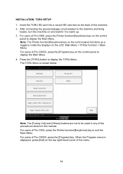
... control panel functions as a toggle to display the TCRU Menu. The TCRU Menu is displayed, press [Exit] on the top right-hand corner of Pro C900, press the Printer function/[fierydriven] key on the control panel to exit the Main Menu. Note: The [Fusing Unit] and [Others] buttons are... not to be used in this manual. For users of the procedures shown in any of Pro C900S, press the [Program] key on the control panel to warm up. 3. For users of Pro C900S, press the [Program] key. For users of Pro C900, press the Printer function/[fierydriven] key to ...
... control panel functions as a toggle to display the TCRU Menu. The TCRU Menu is displayed, press [Exit] on the top right-hand corner of Pro C900, press the Printer function/[fierydriven] key on the control panel to exit the Main Menu. Note: The [Fusing Unit] and [Others] buttons are... not to be used in this manual. For users of the procedures shown in any of Pro C900S, press the [Program] key on the control panel to warm up. 3. For users of Pro C900S, press the [Program] key. For users of Pro C900, press the Printer function/[fierydriven] key to ...
User Guide
Page 16
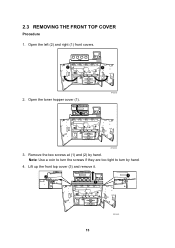
Open the toner hopper cover (1). 1 RPG020S RPG003S 3. Lift up the front top cover (3) and remove it. 2 1 3 15 RPG056S Note: Use a coin to turn the screws if they are too tight to turn by hand. Open the left (2) and right (1) front covers. 2 1 2. 2.3 REMOVING THE FRONT TOP COVER Procedure 1. Remove the two screws at (1) and (2) by hand. 4.
Open the toner hopper cover (1). 1 RPG020S RPG003S 3. Lift up the front top cover (3) and remove it. 2 1 3 15 RPG056S Note: Use a coin to turn the screws if they are too tight to turn by hand. Open the left (2) and right (1) front covers. 2 1 2. 2.3 REMOVING THE FRONT TOP COVER Procedure 1. Remove the two screws at (1) and (2) by hand. 4.
User Guide
Page 18
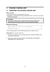
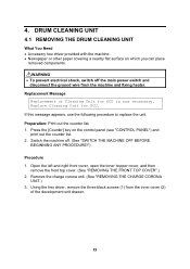
... out the counter list. 2. Preparation: Print out the counter list. 1. Press the [Counter] key on which you can place removed components. If this message appears, use the following procedure to replace the unit. RWARNING • To prevent electrical shock, switch off . (See "SWITCH THE MACHINE OFF BEFORE BEGINNING ANY PROCEDURE!") 17...
... out the counter list. 2. Preparation: Print out the counter list. 1. Press the [Counter] key on which you can place removed components. If this message appears, use the following procedure to replace the unit. RWARNING • To prevent electrical shock, switch off . (See "SWITCH THE MACHINE OFF BEFORE BEGINNING ANY PROCEDURE!") 17...
User Guide
Page 23
...front top cover. (See "REMOVING THE FRONT TOP COVER".) 2. Replacement Message Replacement of the development unit drawer. 22 If this message appears, use the following procedure to replace the unit. Switch the machine off the main power switch and disconnect the ground wire from the inner cover (2) of... Cleaning Unit for PCU. Using the hex driver, remove the three black screws (1) from the machine and fixing heater. Remove the charge corona unit. (See "REMOVING THE ...
...front top cover. (See "REMOVING THE FRONT TOP COVER".) 2. Replacement Message Replacement of the development unit drawer. 22 If this message appears, use the following procedure to replace the unit. Switch the machine off the main power switch and disconnect the ground wire from the inner cover (2) of... Cleaning Unit for PCU. Using the hex driver, remove the three black screws (1) from the machine and fixing heater. Remove the charge corona unit. (See "REMOVING THE ...
User Guide
Page 27
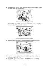
4. Reinstall the charge corona unit. (See "REINSTALLING THE CHARGE CORONA UNIT") 26 Gently and firmly push the purple handle (2) into the machine until the drawer can go no further and locks into place. 2 1 RPG032 Important: Do not pinch the harnesses (1) on the frame when pushing the development unit drawer into the machine. 1 RPG036 5. Attach the inner cover, and then secure it by turning it by turning its three black screws clockwise using the hex driver. 7. Install the drawer stop knob (1), and then fasten it clockwise. 1 RPG035 6.
4. Reinstall the charge corona unit. (See "REINSTALLING THE CHARGE CORONA UNIT") 26 Gently and firmly push the purple handle (2) into the machine until the drawer can go no further and locks into place. 2 1 RPG032 Important: Do not pinch the harnesses (1) on the frame when pushing the development unit drawer into the machine. 1 RPG036 5. Attach the inner cover, and then secure it by turning it by turning its three black screws clockwise using the hex driver. 7. Install the drawer stop knob (1), and then fasten it clockwise. 1 RPG035 6.
User Guide
Page 29
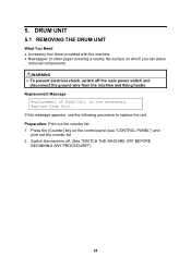
... Drum Unit. Switch the machine off the main power switch and disconnect the ground wire from the machine and fixing heater. 5. If this message appears, use the following procedure to replace the unit. Preparation: Print out the counter list. 1.
... Drum Unit. Switch the machine off the main power switch and disconnect the ground wire from the machine and fixing heater. 5. If this message appears, use the following procedure to replace the unit. Preparation: Print out the counter list. 1.
User Guide
Page 30
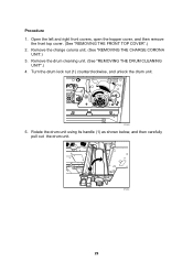
Remove the charge corona unit. (See "REMOVING THE CHARGE CORONA UNIT.) 3. Turn the drum lock nut (1) counterclockwise, and unlock the drum unit. 1 RPG063 5. Remove the drum cleaning unit. (See "REMOVING THE DRUM CLEANING UNIT".) 4. Rotate the drum unit using its handle (1) as shown below, and then carefully pull out the drum unit. 1 RPG034 29 Open the left and right front covers, open the hopper cover, and then remove the front top cover. (See "REMOVING THE FRONT TOP COVER".) 2. Procedure 1.
Remove the charge corona unit. (See "REMOVING THE CHARGE CORONA UNIT.) 3. Turn the drum lock nut (1) counterclockwise, and unlock the drum unit. 1 RPG063 5. Remove the drum cleaning unit. (See "REMOVING THE DRUM CLEANING UNIT".) 4. Rotate the drum unit using its handle (1) as shown below, and then carefully pull out the drum unit. 1 RPG034 29 Open the left and right front covers, open the hopper cover, and then remove the front top cover. (See "REMOVING THE FRONT TOP COVER".) 2. Procedure 1.
User Guide
Page 32
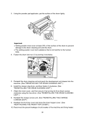
... inert substance that is not harmful to the human body. 4. Attach the inner cover, and then secure it clockwise. (See "REINSTALLING THE DRUM CLEANING UNIT".) 7. Using the powder pad applicator, pat the surface of the drum lightly. 25% RPG019S Important: • Setting powder must cover at least 25% of the surface... of the machine and fixing heater. 31 Fasten the drum lock nut (1) by turning its three black screws clockwise using the hex driver. (See "REINSTALLING THE DRUM CLEANING UNIT".) 8.
... inert substance that is not harmful to the human body. 4. Attach the inner cover, and then secure it clockwise. (See "REINSTALLING THE DRUM CLEANING UNIT".) 7. Using the powder pad applicator, pat the surface of the drum lightly. 25% RPG019S Important: • Setting powder must cover at least 25% of the surface... of the machine and fixing heater. 31 Fasten the drum lock nut (1) by turning its three black screws clockwise using the hex driver. (See "REINSTALLING THE DRUM CLEANING UNIT".) 8.
User Guide
Page 34
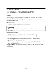
Replacement Message Replacement of the developer bottle in your area. Preparation: Print out the counter list. 1. Important: Before this message appears, use the following procedure to replace the unit. DEVELOPER 6.1 REMOVING THE USED DEVELOPER Overview You can be carried out, the machine must be switched on the control panel (see "CONTROL PANEL") and...
Replacement Message Replacement of the developer bottle in your area. Preparation: Print out the counter list. 1. Important: Before this message appears, use the following procedure to replace the unit. DEVELOPER 6.1 REMOVING THE USED DEVELOPER Overview You can be carried out, the machine must be switched on the control panel (see "CONTROL PANEL") and...

User Guide
Page 42
... machine off the main power switch and disconnect the ground wire from the machine and fixing heater. Replacement Message Intermed. Trans. If this message appears, use the following procedure to replace the unit. 7. Belt Cleaning Unit. RWARNING • To prevent electrical shock, switch off . (See "SWITCH THE MACHINE OFF BEFORE BEGINNING...
... machine off the main power switch and disconnect the ground wire from the machine and fixing heater. Replacement Message Intermed. Trans. If this message appears, use the following procedure to replace the unit. 7. Belt Cleaning Unit. RWARNING • To prevent electrical shock, switch off . (See "SWITCH THE MACHINE OFF BEFORE BEGINNING...

User Guide
Page 43
Remove the two black screws (1) on the image transfer belt cleaning unit using the hex driver. 3. Remove the inner cover (2). Rotate the cleaning blade contact lever (2) clockwise. 1 2 RPG038 42 Remove the black screw (1) on the inner cover (2) for the image transfer belt cleaning unit using the hex driver. 5. Note: To remove the inner cover, pull it out and slightly upward. 1 2 1 RPG044 4. Procedure 1. Open the left and right front covers. 2.
Remove the two black screws (1) on the image transfer belt cleaning unit using the hex driver. 3. Remove the inner cover (2). Rotate the cleaning blade contact lever (2) clockwise. 1 2 RPG038 42 Remove the black screw (1) on the inner cover (2) for the image transfer belt cleaning unit using the hex driver. 5. Note: To remove the inner cover, pull it out and slightly upward. 1 2 1 RPG044 4. Procedure 1. Open the left and right front covers. 2.

