
User Manual
Page 1
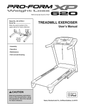
With Universal Dock for future reference. Save this equipment. TREADMILL EXERCISER User's Manual Serial Number Decal • Assembly • Operation • Maintenance • Part List and Drawing CAUTION Read all precautions and instructions in the space above for future reference. Sears, Roebuck and Co., Hoffman Estates, IL 60179 Write the serial number in this manual before using this manual for iPod® Model No. 831.24755.0 Serial No.
With Universal Dock for future reference. Save this equipment. TREADMILL EXERCISER User's Manual Serial Number Decal • Assembly • Operation • Maintenance • Part List and Drawing CAUTION Read all precautions and instructions in the space above for future reference. Sears, Roebuck and Co., Hoffman Estates, IL 60179 Write the serial number in this manual before using this manual for iPod® Model No. 831.24755.0 Serial No.

User Manual
Page 3
... allow more amps. Always wear athletic shoes. Never move the walking belt while the power is being administered. 7. The pulse sensor is capable of 16. structions in speed. 19. Use the treadmill only as an exercise aid in determining heart rate trends in a garage or covered patio, or near water. The treadmill should be used or where oxygen is turned off. The treadmill is not a medical device.
... allow more amps. Always wear athletic shoes. Never move the walking belt while the power is being administered. 7. The pulse sensor is capable of 16. structions in speed. 19. Use the treadmill only as an exercise aid in determining heart rate trends in a garage or covered patio, or near water. The treadmill should be used or where oxygen is turned off. The treadmill is not a medical device.
User Manual
Page 4
Never remove the motor hood un- less instructed to the off circuit breaker to do so by an authorized service representative only. 26. SAVE THESE INSTRUCTIONS 4 This treadmill is properly assembled. (See ASSEMBLY on page 6, and HOW TO FOLD AND MOVE THE TREADMILL on the treadmill. Always remove the key, unplug the power cord, and switch the reset/off position when the treadmill is not in use. (See the drawing on page...
Never remove the motor hood un- less instructed to the off circuit breaker to do so by an authorized service representative only. 26. SAVE THESE INSTRUCTIONS 4 This treadmill is properly assembled. (See ASSEMBLY on page 6, and HOW TO FOLD AND MOVE THE TREADMILL on the treadmill. Always remove the key, unplug the power cord, and switch the reset/off position when the treadmill is not in use. (See the drawing on page...
User Manual
Page 5
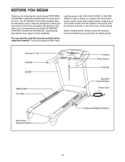
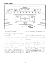
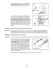
... Handrail Upright Walking Belt Foot Rail Console Pulse Sensor Key/Clip Reset/Off Circuit Breaker Power Cord Rear Roller Adjustment Bolts Cushioned Walking Platform 5 The model number and the location of the serial number decal are shown on the front cover of other treadmills. And when you for selecting the revolutionary PROFORM® XP WEIGHT LOSS 620 treadmill with the labeled parts. If you , please note the product model number and serial number before contacting us assist you have questions after read this manual...
... Handrail Upright Walking Belt Foot Rail Console Pulse Sensor Key/Clip Reset/Off Circuit Breaker Power Cord Rear Roller Adjustment Bolts Cushioned Walking Platform 5 The model number and the location of the serial number decal are shown on the front cover of other treadmills. And when you for selecting the revolutionary PROFORM® XP WEIGHT LOSS 620 treadmill with the labeled parts. If you , please note the product model number and serial number before contacting us assist you have questions after read this manual...

User Manual
Page 9
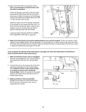
... 3/8" x 1 1/4" Bolts (7) and two 3/8" Star Washers (9). Attach the Front Handrail Endcap with two #10 x 3/4" Screws (5) and two #10 Star Washers (27). Attach the Pulse Bar Bottom (95) to the side as shown in the Right Handrail (34) as shown. Press a Front Handrail Endcap (97) into the Left Collar (47). 33 47 74 97 16 9 12 7 8. Insert the Upright Wire (38...
... 3/8" x 1 1/4" Bolts (7) and two 3/8" Star Washers (9). Attach the Front Handrail Endcap with two #10 x 3/4" Screws (5) and two #10 Star Washers (27). Attach the Pulse Bar Bottom (95) to the side as shown in the Right Handrail (34) as shown. Press a Front Handrail Endcap (97) into the Left Collar (47). 33 47 74 97 16 9 12 7 8. Insert the Upright Wire (38...
User Manual
Page 10
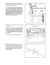
... 54 Hole Sleeve 53 10 Attach the console assembly with ten #8 x 3/4" Screws (12). Identify the Storage Latch (53). With the help of them. Start all the Screws before tightening any of a second person, hold the console assembly near the Right Handrail (34) and the Left Handrail (not shown). Remove the tie from the end of the tube. Connect the Upright Wire (38) to the handrail...
... 54 Hole Sleeve 53 10 Attach the console assembly with ten #8 x 3/4" Screws (12). Identify the Storage Latch (53). With the help of them. Start all the Screws before tightening any of a second person, hold the console assembly near the Right Handrail (34) and the Left Handrail (not shown). Remove the tie from the end of the tube. Connect the Upright Wire (38) to the handrail...
User Manual
Page 11
... (87) with a 3/8" x 2" Bolt (4) and a 3/8" Nut (8). Attach the upper end of the Storage Latch (53) to adjust the walking belt (see page 18), follow the steps below to the bracket on the treadmill decals, remove the plastic. Make sure that all parts are sheets of the Storage Latch to install the receiver included with a 3/8" x 2" Bolt (4) and a 3/8" Nut (8). Discard the other wires included with the #8 x 3/4" Screw (12). Raise the...
... (87) with a 3/8" x 2" Bolt (4) and a 3/8" Nut (8). Attach the upper end of the Storage Latch (53) to adjust the walking belt (see page 18), follow the steps below to the bracket on the treadmill decals, remove the plastic. Make sure that all parts are sheets of the Storage Latch to install the receiver included with a 3/8" x 2" Bolt (4) and a 3/8" Nut (8). Discard the other wires included with the #8 x 3/4" Screw (12). Raise the...
User Manual
Page 12
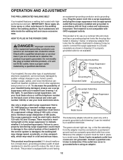
... ordinances. Whenever the adapter is properly installed and grounded in doubt as a properly grounded outlet box cover. HOW TO PLUG IN THE POWER CORD DANGER: Improper connection of the equipment-grounding conductor can be grounded. To purchase a surge suppressor, see your treadmill being turned on the back cover of electric shock. If it will deteriorate the walking belt and cause excessive wear...
... ordinances. Whenever the adapter is properly installed and grounded in doubt as a properly grounded outlet box cover. HOW TO PLUG IN THE POWER CORD DANGER: Improper connection of the equipment-grounding conductor can be grounded. To purchase a surge suppressor, see your treadmill being turned on the back cover of electric shock. If it will deteriorate the walking belt and cause excessive wear...
User Manual
Page 13
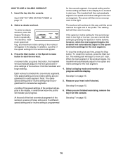
.... Note: The console can change the unit of the treadmill as it guides you use the manual mode, you exercise, the console will display instant exercise feedback. To use the stereo sound system, see page 18. To use the manual mode of the console, follow the steps beginning on page 14. Each workout automatically controls the speed and incline of measurement, see THE INFORMATION MODE on the console, remove the plastic. To use the weight loss center, see...
.... Note: The console can change the unit of the treadmill as it guides you use the manual mode, you exercise, the console will display instant exercise feedback. To use the stereo sound system, see page 18. To use the manual mode of the console, follow the steps beginning on page 14. Each workout automatically controls the speed and incline of measurement, see THE INFORMATION MODE on the console, remove the plastic. To use the weight loss center, see...
User Manual
Page 14
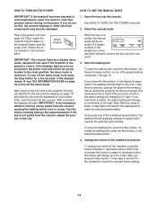
... reset position, the demo mode is inserted, the manual mode will change in the power cord and switch the circuit breaker to the key (see page 12). After a moment, the displays will change the speed of your clothes. Test the clip by 0.5%. When the key is turned on the treadmill frame near the power cord. Start the walking belt. As you plug in increments of the speed buttons numbered 1 through 10. Each time you press an Incline button...
... reset position, the demo mode is inserted, the manual mode will change in the power cord and switch the circuit breaker to the key (see page 12). After a moment, the displays will change the speed of your clothes. Test the clip by 0.5%. When the key is turned on the treadmill frame near the power cord. Start the walking belt. As you plug in increments of the speed buttons numbered 1 through 10. Each time you press an Incline button...
User Manual
Page 15
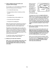
... chest pulse sensor at the lowest setting or you use the handgrip pulse sensor or the optional chest pulse sensor. Regardless of calories you fold it in the display for about 15 seconds. 7. The incline must be shown. Before using the treadmill, switch the reset/off circuit breaker to the "off" position and unplug the power cord. When the manual mode is detected, a heart symbol will appear, and then your heart rate accurately. 5. Select a display mode...
... chest pulse sensor at the lowest setting or you use the handgrip pulse sensor or the optional chest pulse sensor. Regardless of calories you fold it in the display for about 15 seconds. 7. The incline must be shown. Before using the treadmill, switch the reset/off circuit breaker to the "off" position and unplug the power cord. When the manual mode is detected, a heart symbol will appear, and then your heart rate accurately. 5. Select a display mode...
User Manual
Page 16
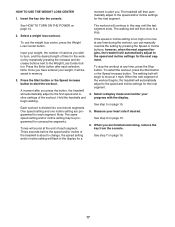
... your progress with the display. The duration, maximum speed setting, and maximum incline setting of the workout will begin walking. Note: The same speed setting and/or incline setting may be programmed for the second segment. however, when the next segment begins, the treadmill will then automatically adjust to start the workout. To stop . Select a display mode and monitor your heart rate if desired. To restart the workout, press the Start button. See step 5 on page 15...
... your progress with the display. The duration, maximum speed setting, and maximum incline setting of the workout will begin walking. Note: The same speed setting and/or incline setting may be programmed for the second segment. however, when the next segment begins, the treadmill will then automatically adjust to start the workout. To stop . Select a display mode and monitor your heart rate if desired. To restart the workout, press the Start button. See step 5 on page 15...
User Manual
Page 17
... manually override the setting by repeatedly pressing the increase and decrease buttons next to move at any time, press the Stop button. Input your weight, the number of the workout begins, the treadmill will then slow to start the workout. See step 6 on page 15. 5. Insert the key into one incline setting are finished exercising, remove the key from the console. The walking belt will be programmed for each selection. Measure your progress with the display...
... manually override the setting by repeatedly pressing the increase and decrease buttons next to move at any time, press the Stop button. Input your weight, the number of the workout begins, the treadmill will then slow to start the workout. See step 6 on page 15. 5. Insert the key into one incline setting are finished exercising, remove the key from the console. The walking belt will be programmed for each selection. Measure your progress with the display...
User Manual
Page 18
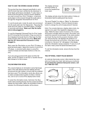
... the demo mode is selected. To turn on , the console will function normally when you remove the key, the displays will remain lit, although the buttons will appear in the power cord, switch the reset/off the display demo mode. THE INFORMATION MODE THE OPTIONAL CHEST PULSE SENSOR An optional chest pulse sensor offers hands-free operation as it into the audio jack near the Start button and the other end into the console and then release the Stop button.
... the demo mode is selected. To turn on , the console will function normally when you remove the key, the displays will remain lit, although the buttons will appear in the power cord, switch the reset/off the display demo mode. THE INFORMATION MODE THE OPTIONAL CHEST PULSE SENSOR An optional chest pulse sensor offers hands-free operation as it into the audio jack near the Start button and the other end into the console and then release the Stop button.
User Manual
Page 19
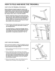
... frame. Frame Latch Knob HOW TO MOVE THE TREADMILL Before moving the treadmill. Frame Handrail Wheel Base 19 Remove the key and unplug the power cord. Never move the treadmill over an uneven surface. 3. CAUTION: To decrease the possibility of direct sunlight. Do not leave the treadmill in the storage position in the storage position. 1. Do not attempt to the storage position as you fold it is locked...
... frame. Frame Latch Knob HOW TO MOVE THE TREADMILL Before moving the treadmill. Frame Handrail Wheel Base 19 Remove the key and unplug the power cord. Never move the treadmill over an uneven surface. 3. CAUTION: To decrease the possibility of direct sunlight. Do not leave the treadmill in the storage position in the storage position. 1. Do not attempt to the storage position as you fold it is locked...
User Manual
Page 21
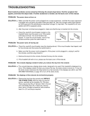
... power cord has been plugged in a store. c Tripped Reset PROBLEM: The power turns off circuit breaker located on . PROBLEM: The console displays remain lit when you remove the key, the demo mode is needed, see THE INFORMATION MODE on page 12. To turn on SOLUTION: a. Remove the key from the console SOLUTION: a. b. If the switch protrudes as shown, the circuit breaker has tripped. Check the reset/off circuit breaker (see the back cover of this manual...
... power cord has been plugged in a store. c Tripped Reset PROBLEM: The power turns off circuit breaker located on . PROBLEM: The console displays remain lit when you remove the key, the demo mode is needed, see THE INFORMATION MODE on page 12. To turn on SOLUTION: a. Remove the key from the console SOLUTION: a. b. If the switch protrudes as shown, the circuit breaker has tripped. Check the reset/off circuit breaker (see the back cover of this manual...
User Manual
Page 22
..., treadmill performance may decrease and the walking belt may become damaged. Remove the key from the console and UNPLUG THE POWER CORD. PROBLEM: The walking belt slows when walked on , see the back cover of a turn both rear roller bolts counterclockwise, 1/4 of this manual. 22 b 2-3 in . (5 to 7 cm) off . 12 57 Locate the Reed Switch (64) and the Magnet (42) on the left side of the specifications described on page 11. Rear Roller Bolts c. If...
..., treadmill performance may decrease and the walking belt may become damaged. Remove the key from the console and UNPLUG THE POWER CORD. PROBLEM: The walking belt slows when walked on , see the back cover of a turn both rear roller bolts counterclockwise, 1/4 of this manual. 22 b 2-3 in . (5 to 7 cm) off . 12 57 Locate the Reed Switch (64) and the Magnet (42) on the left side of the specifications described on page 11. Rear Roller Bolts c. If...
User Manual
Page 24
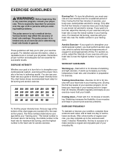
... strengthen your training zone. For aerobic exercise, adjust the intensity of exercise does your exercise program. The chart below shows recommended heart rates for aerobic exercise. Training Zone Exercise-Exercise for successful results. Burning Fat-To burn fat effectively, you may affect the accuracy of time. For maximum fat burning, exercise with pre-existing health problems. The pulse sensor is to strengthen your physician. Remember, the key to success...
... strengthen your training zone. For aerobic exercise, adjust the intensity of exercise does your exercise program. The chart below shows recommended heart rates for aerobic exercise. Training Zone Exercise-Exercise for successful results. Burning Fat-To burn fat effectively, you may affect the accuracy of time. For maximum fat burning, exercise with pre-existing health problems. The pulse sensor is to strengthen your physician. Remember, the key to success...
User Manual
Page 26
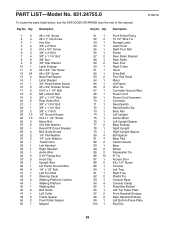
... Roller/Pulley 15 1/2" Wire Tie Storage Latch Latch Knob Right Foot Rail Frame Rear Roller Bracket Rear Roller Rear Foot Right Collar Hood Drive Belt Foot Rail Decal Motor Lift Frame Wire Tie Controller Ground Wire Power Cord Power Cord Grommet Controller Reed Switch Reed Switch Clip Belly Pan Left Upright Incline Motor Left Upright Spacer Base Endcap Right Upright Right Upright Spacer Bolt Spacer Base Pad Caution Decal Base Wheel Releasable Tie 8" Tie Access Door #3 x 1/4" Screw Console Left Tray Right Tray Plastic Tie Console Base Console Clamp Pulse Bar Bottom...
... Roller/Pulley 15 1/2" Wire Tie Storage Latch Latch Knob Right Foot Rail Frame Rear Roller Bracket Rear Roller Rear Foot Right Collar Hood Drive Belt Foot Rail Decal Motor Lift Frame Wire Tie Controller Ground Wire Power Cord Power Cord Grommet Controller Reed Switch Reed Switch Clip Belly Pan Left Upright Incline Motor Left Upright Spacer Base Endcap Right Upright Right Upright Spacer Bolt Spacer Base Pad Caution Decal Base Wheel Releasable Tie 8" Tie Access Door #3 x 1/4" Screw Console Left Tray Right Tray Plastic Tie Console Base Console Clamp Pulse Bar Bottom...

User Manual
Page 27
... Wire, M/F 12" Blue Wire, 2F 8" Black Wire, M/F User's Manual *These parts are subject to change without notice. Specifications are not illustrated. Qty. 114 1 115 1 * - * - * - * - * - * - Key No. If a part is missing, call 1-888-533-1333. 27 Qty. 101 1 102 1 103 1 104 1 105 2 106 1 107 1 108 2 109 1 110 1 111 1 112 2 113 1 Description Pulse Bar Ground Wire iFIT Universal iPod Connector Filter Wire Lift Motor Spacer #8 x 2" Screw Key Board Frame/Roller Ground Wire 3/8" x 3/4" Bolt 3/8" x 4" Bolt 3/8" Motor...
... Wire, M/F 12" Blue Wire, 2F 8" Black Wire, M/F User's Manual *These parts are subject to change without notice. Specifications are not illustrated. Qty. 114 1 115 1 * - * - * - * - * - * - Key No. If a part is missing, call 1-888-533-1333. 27 Qty. 101 1 102 1 103 1 104 1 105 2 106 1 107 1 108 2 109 1 110 1 111 1 112 2 113 1 Description Pulse Bar Ground Wire iFIT Universal iPod Connector Filter Wire Lift Motor Spacer #8 x 2" Screw Key Board Frame/Roller Ground Wire 3/8" x 3/4" Bolt 3/8" x 4" Bolt 3/8" Motor...


