

Canadian English Manual
Page 1
Serial Number Decal QUESTIONS? Model No. 30841.0 Serial No. If you have questions, or if parts are damaged or missing, PLEASE CONTACT OUR CUSTOMER SERVICE DEPARTMENT DIRECTLY. CALL TOLL-FREE: 1-888-936-4266 Mon.-Fri., 7:30 until 16:30 ET (excluding holidays) OR E-MAIL US: [email protected] CAUTION Read all precautions and instructions in the space above for future reference. Keep this equipment. USERʼS MANUAL www.proform.com Write the serial number in this manual before using this manual for reference.
Serial Number Decal QUESTIONS? Model No. 30841.0 Serial No. If you have questions, or if parts are damaged or missing, PLEASE CONTACT OUR CUSTOMER SERVICE DEPARTMENT DIRECTLY. CALL TOLL-FREE: 1-888-936-4266 Mon.-Fri., 7:30 until 16:30 ET (excluding holidays) OR E-MAIL US: [email protected] CAUTION Read all precautions and instructions in the space above for future reference. Keep this equipment. USERʼS MANUAL www.proform.com Write the serial number in this manual before using this manual for reference.
Canadian English Manual
Page 2
... PRECAUTIONS 3 BEFORE YOU BEGIN 4 ASSEMBLY 5 HOW TO USE THE EXERCISE CYCLE 11 MAINTENANCE AND TROUBLESHOOTING 17 EXERCISE GUIDELINES 18 PART LIST 22 EXPLODED DRAWING 23 ORDERING REPLACEMENT PARTS Back Cover LIMITED WARRANTY Back Cover WARNING DECAL PLACEMENT This drawing shows the location(s) of this manual and request a free replacement decal. Note: The decal(s) may not be shown at actual size. If a decal is a registered trademark of ICON IP, Inc. 2 Apply...
... PRECAUTIONS 3 BEFORE YOU BEGIN 4 ASSEMBLY 5 HOW TO USE THE EXERCISE CYCLE 11 MAINTENANCE AND TROUBLESHOOTING 17 EXERCISE GUIDELINES 18 PART LIST 22 EXPLODED DRAWING 23 ORDERING REPLACEMENT PARTS Back Cover LIMITED WARRANTY Back Cover WARNING DECAL PLACEMENT This drawing shows the location(s) of this manual and request a free replacement decal. Note: The decal(s) may not be shown at actual size. If a decal is a registered trademark of ICON IP, Inc. 2 Apply...
Canadian English Manual
Page 3
..., away from your exercise cycle. 5. The pulse sensor is the responsibility of heart rate readings. ICON assumes no responsibility for persons over the age of the holes in the seat post. Always wear athletic shoes for home use only. Do not insert the seat pin under age 12 and pets away from moisture and dust. Replace any exercise program, consult your exercise cycle. Do not...
..., away from your exercise cycle. 5. The pulse sensor is the responsibility of heart rate readings. ICON assumes no responsibility for persons over the age of the holes in the seat post. Always wear athletic shoes for home use only. Do not insert the seat pin under age 12 and pets away from moisture and dust. Replace any exercise program, consult your exercise cycle. Do not...
Canadian English Manual
Page 4
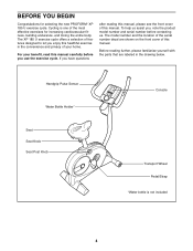
... the parts that are shown on the front cover of the most effective exercises for selecting the new PROFORM® XP 185 U exercise cycle. For your home. To help us . Handgrip Pulse Sensor Water Bottle Holder* Seat Seat Knob Seat Post Knob Console Transport Wheel Pedal/Strap *Water bottle is one of this manual carefully before you , note the product model number and serial number before contacting us assist you use the exercise cycle. The XP 185 U exercise...
... the parts that are shown on the front cover of the most effective exercises for selecting the new PROFORM® XP 185 U exercise cycle. For your home. To help us . Handgrip Pulse Sensor Water Bottle Holder* Seat Seat Knob Seat Post Knob Console Transport Wheel Pedal/Strap *Water bottle is one of this manual carefully before you , note the product model number and serial number before contacting us assist you use the exercise cycle. The XP 185 U exercise...
Canadian English Manual
Page 5
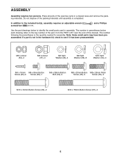
... Button Screw (40)-9 Screw (56)-1 M6 x 38mm Button Bolt (53)-4 M8 x 20mm Button M8 x 25mm Patch Screw (35)-4 Screw (50)-2 M10 x 54mm Button Screw (33)-2 M10 x 78mm Button Screw (67)-2 5 The number following the parentheses is not in assembly. In addition to the key number of the part, from the PART LIST near the end of the exercise cycle in a cleared area and remove the packing materials. and a Phillips Use the part drawings...
... Button Screw (40)-9 Screw (56)-1 M6 x 38mm Button Bolt (53)-4 M8 x 20mm Button M8 x 25mm Patch Screw (35)-4 Screw (50)-2 M10 x 54mm Button Screw (33)-2 M10 x 78mm Button Screw (67)-2 5 The number following the parentheses is not in assembly. In addition to the key number of the part, from the PART LIST near the end of the exercise cycle in a cleared area and remove the packing materials. and a Phillips Use the part drawings...
Canadian English Manual
Page 6
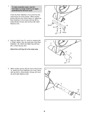
... the Rear Stabilizer (14) so that the indicated holes are at the bottom. Slide the Right Cap (77), which is marked with two M10 x 54mm Button Screws (33) and two M10 Split Washers (34). 1 Holes 34 33 1 14 Holes 2. To make assembly easier, read the information on page 5 before you begin assembling the exercise cycle. 1. Attach the Left...
... the Rear Stabilizer (14) so that the indicated holes are at the bottom. Slide the Right Cap (77), which is marked with two M10 x 54mm Button Screws (33) and two M10 Split Washers (34). 1 Holes 34 33 1 14 Holes 2. To make assembly easier, read the information on page 5 before you begin assembling the exercise cycle. 1. Attach the Left...
Canadian English Manual
Page 7
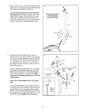
... Split Washers (36). Do not tighten the Screw yet. 5 47 Left Pulse Wire Pull Wire Right Pulse Wire 40 49 32 Right Pulse Hexagonal Holes Wire 3 54 Pull Wire 48 43 53 7 Attach the Upright with two M6 x 38mm Button Bolts (53), two M6 Split Washers (43), and two M6 Nylon Locknuts (54). Avoid pinching the wire harnesses during this step 3 36 35 36 35 36...
... Split Washers (36). Do not tighten the Screw yet. 5 47 Left Pulse Wire Pull Wire Right Pulse Wire 40 49 32 Right Pulse Hexagonal Holes Wire 3 54 Pull Wire 48 43 53 7 Attach the Upright with two M6 x 38mm Button Bolts (53), two M6 Split Washers (43), and two M6 Nylon Locknuts (54). Avoid pinching the wire harnesses during this step 3 36 35 36 35 36...
Canadian English Manual
Page 8
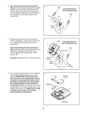
... to cold temperatures, allow it to warm to the pulse wires. Attach the Console Bracket to the Upright (3) with four M4 x 16mm Screws (40). alkaline batteries are recommended. Tighten the M4 x 16mm Screw (40). 7 6 Console Wires Pulse Wires 8. Remove the battery cover, insert the batteries into the Upright (3). Tip: Avoid pinching the wires during this step. See step 5. Otherwise, you may damage the console displays or other electronic components. 6. Make sure to the...
... to cold temperatures, allow it to warm to the pulse wires. Attach the Console Bracket to the Upright (3) with four M4 x 16mm Screws (40). alkaline batteries are recommended. Tighten the M4 x 16mm Screw (40). 7 6 Console Wires Pulse Wires 8. Remove the battery cover, insert the batteries into the Upright (3). Tip: Avoid pinching the wires during this step. See step 5. Otherwise, you may damage the console displays or other electronic components. 6. Make sure to the...

Canadian English Manual
Page 9
... it stops. Attach the Seat to the desired position and tighten the Seat Knob. 10 12 36 37 1 30 56 5 29 11 36 9 9. Then, adjust the Seat Carriage to the Seat Carriage with four M8 Nylon Locknuts (37) and four M8 Split Washers (36). Orient the Seat Post (5) as shown. Next, attach an M6 x 8mm Button Screw (56) to make sure that the pin...
... it stops. Attach the Seat to the desired position and tighten the Seat Knob. 10 12 36 37 1 30 56 5 29 11 36 9 9. Then, adjust the Seat Carriage to the Seat Carriage with four M8 Nylon Locknuts (37) and four M8 Split Washers (36). Orient the Seat Post (5) as shown. Next, attach an M6 x 8mm Button Screw (56) to make sure that the pin...

Canadian English Manual
Page 10
... 26 Strap Tab 12. Adjust the strap on the Right Pedal (26) to protect the floor. 10 IMPORTANT: Tighten both Pedals as firmly as possible. Make sure that all parts are properly tightened before you use the exercise cycle. Note: After assembly is marked 11 with an "R." Place a mat beneath the exercise cycle to the desired position, and press the end of the Crank...
... 26 Strap Tab 12. Adjust the strap on the Right Pedal (26) to protect the floor. 10 IMPORTANT: Tighten both Pedals as firmly as possible. Make sure that all parts are properly tightened before you use the exercise cycle. Note: After assembly is marked 11 with an "R." Place a mat beneath the exercise cycle to the desired position, and press the end of the Crank...
Canadian English Manual
Page 11
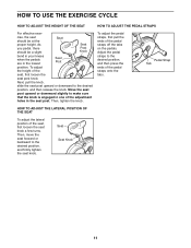
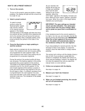
... the seat post knob. HOW TO USE THE EXERCISE CYCLE HOW TO ADJUST THE HEIGHT OF THE SEAT HOW TO ADJUST THE PEDAL STRAPS For effective exer- Seat Seat Knob 11 Then, tighten the knob. To adjust the height of the seat, first loosen the seat knob a few turns. cise, the seat should be at the Seat proper height. Move the seat post upward or downward slightly to the desired position, and then press...
... the seat post knob. HOW TO USE THE EXERCISE CYCLE HOW TO ADJUST THE HEIGHT OF THE SEAT HOW TO ADJUST THE PEDAL STRAPS For effective exer- Seat Seat Knob 11 Then, tighten the knob. To adjust the height of the seat, first loosen the seat knob a few turns. cise, the seat should be at the Seat proper height. Move the seat post upward or downward slightly to the desired position, and then press...
Canadian English Manual
Page 12
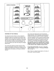
... Weight Loss workout. The console also features the new iFit Interactive Workout System. iFit workouts control the resistance of the pedals while guiding you through your workouts. iFit cards are also available at select stores. iFit cards are available separately. To use a preset workout, see page 15. To use an iFit workout, see page 13. CONSOLE DIAGRAM FEATURES OF THE CONSOLE The advanced console offers an array of features designed to make your heart rate using the handgrip pulse sensor...
... Weight Loss workout. The console also features the new iFit Interactive Workout System. iFit workouts control the resistance of the pedals while guiding you through your workouts. iFit cards are also available at select stores. iFit cards are available separately. To use a preset workout, see page 15. To use an iFit workout, see page 13. CONSOLE DIAGRAM FEATURES OF THE CONSOLE The advanced console offers an array of features designed to make your heart rate using the handgrip pulse sensor...
Canadian English Manual
Page 13
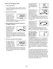
... entire track appears. to the manual mode, press the Workout button. 13 Note: After you replace the batteries, it will appear in either miles or kilometers. Follow your heart rate when you turn the Resistance dial counterclockwise. Note: When you exercise, indicators will take a moment for the pedals to reselect the unit of hours the exercise cycle has been used will again begin pedaling. The display will show speed and distance...
... entire track appears. to the manual mode, press the Workout button. 13 Note: After you replace the batteries, it will appear in either miles or kilometers. Follow your heart rate when you turn the Resistance dial counterclockwise. Note: When you exercise, indicators will take a moment for the pedals to reselect the unit of hours the exercise cycle has been used will again begin pedaling. The display will show speed and distance...
Canadian English Manual
Page 14
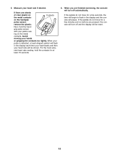
.... Next, hold the contacts for a few minutes and no buttons are finished exercising, the console will be reset. 14 If the pedals do not move for at least 15 seconds. 6. When your pulse is detected, a heart-shaped symbol will flash in the display and the console will be shown. Measure your heart rate will turn off automatically. ing on the handgrip pulse sensor, remove the plastic.
.... Next, hold the contacts for a few minutes and no buttons are finished exercising, the console will be reset. 14 If the pedals do not move for at least 15 seconds. 6. When your pulse is detected, a heart-shaped symbol will flash in the display and the console will be shown. Measure your heart rate will turn off automatically. ing on the handgrip pulse sensor, remove the plastic.
Canadian English Manual
Page 15
... pace setting are finished exercising, the console will prompt you stop pedaling for the next segment, the resistance level will begin to pedal after the workout is completed, the display will last. As you . If the resistance level for you exercise, the display will turn on the sides of the profile will continue until you are programmed for use. 2. however, the display will show your heart rate if...
... pace setting are finished exercising, the console will prompt you stop pedaling for the next segment, the resistance level will begin to pedal after the workout is completed, the display will last. As you . If the resistance level for you exercise, the display will turn on the sides of the profile will continue until you are programmed for use. 2. however, the display will show your heart rate if...

Canadian English Manual
Page 16
... an iFit card and select a workout. iFit Slot iFit Card 16 When the iFit card is oriented so the metal contacts are face-down buttons next to the slot will light and words will be ready for use an iFit workout, insert an iFit card into the iFit slot; Next, select the desired workout on the console, the display will light. Press the Start button or begin pedaling to turn on the iFit card by pressing...
... an iFit card and select a workout. iFit Slot iFit Card 16 When the iFit card is oriented so the metal contacts are face-down buttons next to the slot will light and words will be ready for use an iFit workout, insert an iFit card into the iFit slot; Next, select the desired workout on the console, the display will light. Press the Start button or begin pedaling to turn on the iFit card by pressing...
Canadian English Manual
Page 17
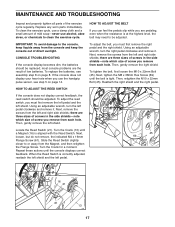
... TO ADJUST THE REED SWITCH If the console does not display correct feedback, the reed switch should be adjusted. Next, remove the screws from the left shield. MAINTENANCE AND TROUBLESHOOTING Inspect and properly tighten all parts of direct sunlight. HOW TO ADJUST THE BELT If you can feel the pedals slip while you are three sizes of screws in the side shields-note which size of mild soap-never use the handgrip pulse sensor, see assembly step...
... TO ADJUST THE REED SWITCH If the console does not display correct feedback, the reed switch should be adjusted. Next, remove the screws from the left shield. MAINTENANCE AND TROUBLESHOOTING Inspect and properly tighten all parts of direct sunlight. HOW TO ADJUST THE BELT If you can feel the pedals slip while you are three sizes of screws in the side shields-note which size of mild soap-never use the handgrip pulse sensor, see assembly step...
Canadian English Manual
Page 18
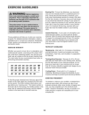
... exercise. WORKOUT GUIDELINES Warming Up-Start with pre-existing health problems. The pulse sensor is the heart rate for prolonged periods of your heart rate is intended only as an exercise aid in determining heart rate trends in your body begin to burn fat, adjust the intensity of exercise does your training zone. Stretching increases the flexibility of time. The lowest number is the heart rate for fat burning, the middle number...
... exercise. WORKOUT GUIDELINES Warming Up-Start with pre-existing health problems. The pulse sensor is the heart rate for prolonged periods of your heart rate is intended only as an exercise aid in determining heart rate trends in your body begin to burn fat, adjust the intensity of exercise does your training zone. Stretching increases the flexibility of time. The lowest number is the heart rate for fat burning, the middle number...
Canadian English Manual
Page 22
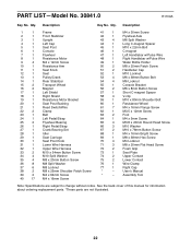
... 4 V-clip 19 1 Resistance Motor Bracket 59 1 M10 x 80mm Shoulder Bolt 20 1 Seat Post Bushing 60 1 Resistance Wheel 21 1 Reed Switch/Wire 61 7 M4 x 16mm Flange Screw 22 2 Clamp 62 1 M3.5 x 12mm Screw 23 1 Belt 63 2 Foot 24 1 Left Pedal/Strap 64 1 M4 x 5mm Screw 25 2 Flywheel Bearing 65 4 M3.8 x 20mm Round Head Screw 26 1 Right Pedal/Strap 66 3 M10 Washer 27 1 Crank Bearing Set 67 2 M10 x 78mm Button Screw 28 1 Idler...
... 4 V-clip 19 1 Resistance Motor Bracket 59 1 M10 x 80mm Shoulder Bolt 20 1 Seat Post Bushing 60 1 Resistance Wheel 21 1 Reed Switch/Wire 61 7 M4 x 16mm Flange Screw 22 2 Clamp 62 1 M3.5 x 12mm Screw 23 1 Belt 63 2 Foot 24 1 Left Pedal/Strap 64 1 M4 x 5mm Screw 25 2 Flywheel Bearing 65 4 M3.8 x 20mm Round Head Screw 26 1 Right Pedal/Strap 66 3 M10 Washer 27 1 Crank Bearing Set 67 2 M10 x 78mm Button Screw 28 1 Idler...
Canadian English Manual
Page 24
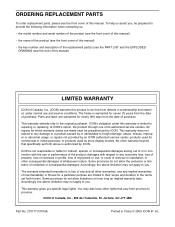
... name of the product (see the front cover of this manual) • the key number and description of the replacement part(s) (see the front cover of this manual. This warranty extends only to the original purchaser. products used as store display models. damages with the use and service conditions. ICON of whatsoever nature. Parts and labor are made must be free from the date of purchase. This...
... name of the product (see the front cover of this manual) • the key number and description of the replacement part(s) (see the front cover of this manual. This warranty extends only to the original purchaser. products used as store display models. damages with the use and service conditions. ICON of whatsoever nature. Parts and labor are made must be free from the date of purchase. This...


