

English Manual
Page 1
... factory. As a manufacturer, we will provide immediate assistance, free of charge to providing you complete customer satisfaction. The trained technicians on our customer hot line will guarantee you . TO AVOID UNNECESSARY DELAYS, PLEASE CALL DIRECT TO OUR TOLL-FREE CUSTOMER HOT LINE. Read all safety precautions and instructions in this manual before using this manual for future reference. OWNER'S MANUAL
... factory. As a manufacturer, we will provide immediate assistance, free of charge to providing you complete customer satisfaction. The trained technicians on our customer hot line will guarantee you . TO AVOID UNNECESSARY DELAYS, PLEASE CALL DIRECT TO OUR TOLL-FREE CUSTOMER HOT LINE. Read all safety precautions and instructions in this manual before using this manual for future reference. OWNER'S MANUAL
English Manual
Page 2
... PROFORM 970 CI TROUBLE-SHOOTING AND MAINTENANCE ORDERING REPLACEMENT PARTS LIMITED WARRANTY 2 3 4 20 23 Back Cover Back Cover IMPORTANT SAFETY PRECAUTIONS WARNING: To reduce the risk of 245 or persons with great force. 7. Read all instructions before using this product. Keep your physician. Always wear athletic shoes for 2 personal injury or property damage sustained by or through the use of the holes, the seat may slip...
... PROFORM 970 CI TROUBLE-SHOOTING AND MAINTENANCE ORDERING REPLACEMENT PARTS LIMITED WARRANTY 2 3 4 20 23 Back Cover Back Cover IMPORTANT SAFETY PRECAUTIONS WARNING: To reduce the risk of 245 or persons with great force. 7. Read all instructions before using this product. Keep your physician. Always wear athletic shoes for 2 personal injury or property damage sustained by or through the use of the holes, the seat may slip...
English Manual
Page 3
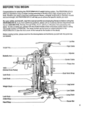
... drawing below and familiarize yourself with the parts that are labeled. 10 3/4" Pin Lat Bar High Cable Butterfly Arm VKR (Vertical Knee Raise) Lock Knob Lock Knob Weight Stack Lock Knob Ankle Strap Hand Strap 0 C 0 0 Adjuster Center Cable Press Arm Dual Hand Strap Leg Lever Low Cable Long Chain Rower Bar 3 The model number is improved cardiovascular fitness, a shapely, toned body or dramatic muscle size and strength, the PROFORM 970 CI will help us assist you have additional...
... drawing below and familiarize yourself with the parts that are labeled. 10 3/4" Pin Lat Bar High Cable Butterfly Arm VKR (Vertical Knee Raise) Lock Knob Lock Knob Weight Stack Lock Knob Ankle Strap Hand Strap 0 C 0 0 Adjuster Center Cable Press Arm Dual Hand Strap Leg Lever Low Cable Long Chain Rower Bar 3 The model number is improved cardiovascular fitness, a shapely, toned body or dramatic muscle size and strength, the PROFORM 970 CI will help us assist you have additional...
English Manual
Page 4
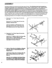
... will be used in assembly. The following tools (not included) are oriented as shown in the drawings. All Pulleys on the weight training system must turn freely or they wilt be damaged. 8 9 9 64 4 8 9 89 1 Attach a Pulley (9) to the size and weight of soapy water are also needed. Attach the Stabilizer w/Bracket (64) to the PART IDENTIFICATION (ID) CHART accompanying this manual for assembly: two 8" adjustable wrenches, a 9/16...
... will be used in assembly. The following tools (not included) are oriented as shown in the drawings. All Pulleys on the weight training system must turn freely or they wilt be damaged. 8 9 9 64 4 8 9 89 1 Attach a Pulley (9) to the size and weight of soapy water are also needed. Attach the Stabilizer w/Bracket (64) to the PART IDENTIFICATION (ID) CHART accompanying this manual for assembly: two 8" adjustable wrenches, a 9/16...
English Manual
Page 6
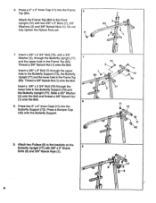
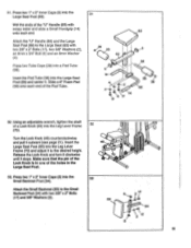
... 11 73 • au .. 1 1r 1 1 (4.4x45 9. Press a 2" x 2" Inner Cap (11) into the Butterfly Support (73). Press two 2" x 2" Inner Caps (11) into the Frame Top (80). Attach two Pulleys (9) to the Front Upright (72) with two 3/8" x 3" Bolts (7), 3/8" Washers (2) and 3/8" Nylock Nuts (1). I . Insert a 3/8" x 2 3/4" Bolt (79), with 3/8" x 2" Shank 9 Bolts (8) and 3/8" Nylock Nyts (1). Do not fully tighten the Nylock Nuts yet. 6 ii 3'. 7 tAr 80...
... 11 73 • au .. 1 1r 1 1 (4.4x45 9. Press a 2" x 2" Inner Cap (11) into the Butterfly Support (73). Press two 2" x 2" Inner Caps (11) into the Frame Top (80). Attach two Pulleys (9) to the Front Upright (72) with two 3/8" x 3" Bolts (7), 3/8" Washers (2) and 3/8" Nylock Nuts (1). I . Insert a 3/8" x 2 3/4" Bolt (79), with 3/8" x 2" Shank 9 Bolts (8) and 3/8" Nylock Nyts (1). Do not fully tighten the Nylock Nuts yet. 6 ii 3'. 7 tAr 80...

English Manual
Page 8
... VKR Frame (67). Wet the Handles (13) with an 8mm x 3/4" Bolt (6) and 8mm Washer (4). 12 28 r • I ''' 9 8 15. Properly tighten all Nylock Nuts used in assembly steps 2 through 15. 47)I 1 6,..- 1 Bracket ' 1- 0" 67 .,- 7 • 76 17. I ,, 76 80 . --,a--,i .0. 1' 78 56 16. Attach the Weight Guide Top to the VKR Upright (76) with soapy water and 17 slide a Large Handgrip (12...
... VKR Frame (67). Wet the Handles (13) with an 8mm x 3/4" Bolt (6) and 8mm Washer (4). 12 28 r • I ''' 9 8 15. Properly tighten all Nylock Nuts used in assembly steps 2 through 15. 47)I 1 6,..- 1 Bracket ' 1- 0" 67 .,- 7 • 76 17. I ,, 76 80 . --,a--,i .0. 1' 78 56 16. Attach the Weight Guide Top to the VKR Upright (76) with soapy water and 17 slide a Large Handgrip (12...
English Manual
Page 9
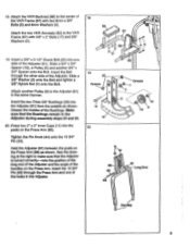
...Adjuster (61) in the Adjuster during assembly steps 24 and 25. 20. Attach another 3/4" x 3/4" Spacer onto the Bolt. lighten the Pin Knob (44) onto the 103/4" Pin (43). Slide a 3/4" x 3/4" Spacer (18), a Pulley (9) and another Pulley (9) to the center of the handles on the Press Arm. Make sure that the Adjuster is turned.... Insert the 103/4" Pin (43) through the other side of the Adjuster (61). Slide a 3/8" Washer (2) onto the Bolt and tighten a 3/8" Nylock Nut (1) onto the Bolt. 18. Hold the Adjuster (61) between the posts on the Press Arm (88). Attach the two VKR Armrests ...
...Adjuster (61) in the Adjuster during assembly steps 24 and 25. 20. Attach another 3/4" x 3/4" Spacer onto the Bolt. lighten the Pin Knob (44) onto the 103/4" Pin (43). Slide a 3/4" x 3/4" Spacer (18), a Pulley (9) and another Pulley (9) to the center of the handles on the Press Arm. Make sure that the Adjuster is turned.... Insert the 103/4" Pin (43) through the other side of the Adjuster (61). Slide a 3/8" Washer (2) onto the Bolt and tighten a 3/8" Nylock Nut (1) onto the Bolt. 18. Hold the Adjuster (61) between the posts on the Press Arm (88). Attach the two VKR Armrests ...
English Manual
Page 10
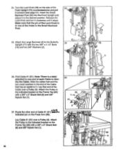
.... Tighten the Pin Knob (44) back onto the 103/4" Pin (43). Attach two Handles (13) to the other side of the 10 3/4" Pin against one . 22 13,14 1 88 4 6 13 14 ,11 14 4 28 14 13 1 3 21. Using a rubber mallet, tap the 7 1/2" Axle (30) into one of the Press Arm (88). Hold one end of the Press Arm (88) in the Adjuster...
.... Tighten the Pin Knob (44) back onto the 103/4" Pin (43). Attach two Handles (13) to the other side of the 10 3/4" Pin against one . 22 13,14 1 88 4 6 13 14 ,11 14 4 28 14 13 1 3 21. Using a rubber mallet, tap the 7 1/2" Axle (30) into one of the Press Arm (88). Hold one end of the Press Arm (88) in the Adjuster...
English Manual
Page 11
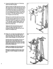
... the Lock Knob and turn it clockwise until it stops. Using an adjustable wrench, tighten the shaft of the Small Seat Frame (36) counterclockwise and pull it to the Butterfly Upright (77) with three 3/8" x 2" Bolts (17) and 3/8" Washers (2). 62 5 2 17 26. Make sure that the pin of the Lock Knob Is In one of two different heights. 23. Attach the Lat Bar Holder (49...
... the Lock Knob and turn it clockwise until it stops. Using an adjustable wrench, tighten the shaft of the Small Seat Frame (36) counterclockwise and pull it to the Butterfly Upright (77) with three 3/8" x 2" Bolts (17) and 3/8" Washers (2). 62 5 2 17 26. Make sure that the pin of the Lock Knob Is In one of two different heights. 23. Attach the Lat Bar Holder (49...
English Manual
Page 12
... Leg Lever (71) with a 3/8" x 2" Shank Bolt (8) and 3/8" Nylock Nut (1). 27. Using an adjustable wrench, tighten the shaft of the Pad Tube. Attach the Leg Lever Frame (70) to the Leg Lever Frame (70) with two 3/8" x 3" Bolts (7), 3/8" Washers (2) and 3/8" Nylock Nuts (1). Note: The Front Upright has three holes so the Pad Tube can be attached at either of three different heights. 28. Press...
... Leg Lever (71) with a 3/8" x 2" Shank Bolt (8) and 3/8" Nylock Nut (1). 27. Using an adjustable wrench, tighten the shaft of the Pad Tube. Attach the Leg Lever Frame (70) to the Leg Lever Frame (70) with two 3/8" x 3" Bolts (7), 3/8" Washers (2) and 3/8" Nylock Nuts (1). Note: The Front Upright has three holes so the Pad Tube can be attached at either of three different heights. 28. Press...
English Manual
Page 13
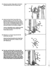
... the Leg Lever Frame (70). Release the Lock Knob and turn it clockwise until it outward (see page 21). Press two 1" x 2" Inner Caps (5) into the 33 Small Backrest Post (34). Turn the Lock Knob (46) counterclockwise and pull it stops. Press two 1" x 2" Inner Caps (5) into the Large Seat Post (69). 31. Make sure that the pin of the Lock Knob Is...
... the Leg Lever Frame (70). Release the Lock Knob and turn it clockwise until it outward (see page 21). Press two 1" x 2" Inner Caps (5) into the 33 Small Backrest Post (34). Turn the Lock Knob (46) counterclockwise and pull it stops. Press two 1" x 2" Inner Caps (5) into the Large Seat Post (69). 31. Make sure that the pin of the Lock Knob Is...
English Manual
Page 14
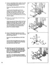
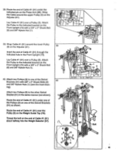
...Frame Top (80) with a 3/8" x 2" Shank Bolt (8) and 3/8" Nylock Nut (1). Lay Cable #1 (91) over a Pulley (9). Attach the Pulley to the end of each Cable to the indicated bracket on the Press Arm (88). I 36 , - , • ..... ...Cable that the pin of the Lock Knob Is in the Small Backrest Post. 35. Find Cable #1 (91). Attach the Pulley to Identify the Cable. 34. Route the other end of the Cable over a Pulley (9). Turn the Lock Knob (46) on it to the Butterfly Upright (77) with a 3/8" x 2" Shank Bolt (8) and 3/8" Nylock Nut (1). Release the Lock Knob and turn...
...Frame Top (80) with a 3/8" x 2" Shank Bolt (8) and 3/8" Nylock Nut (1). Lay Cable #1 (91) over a Pulley (9). Attach the Pulley to the end of each Cable to the indicated bracket on the Press Arm (88). I 36 , - , • ..... ...Cable that the pin of the Lock Knob Is in the Small Backrest Post. 35. Find Cable #1 (91). Attach the Pulley to Identify the Cable. 34. Route the other end of the Cable over a Pulley (9). Turn the Lock Knob (46) on it to the Butterfly Upright (77) with a 3/8" x 2" Shank Bolt (8) and 3/8" Nylock Nut (1). Release the Lock Knob and turn...
English Manual
Page 15
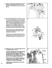
... the Swivel Brackets (51) as shown. Wrap 38 Pin the Cable around the lower Pulley (9) on the Front Upright (72) with a 3/8" x 2" Shank Bolt (8) and 3/8" Nylock Nut (1). 8 39. Lay Cable #1 (91) over a Pulley (9). ing). Lay Cable #1 (91) over a Pulley (9). Route the end of Cable #1 (91) under one of the Pulleys (9) on the Weight Guide Top (78). Attach the Pulley to one of the Swivel 40 Brackets (51) with...
... the Swivel Brackets (51) as shown. Wrap 38 Pin the Cable around the lower Pulley (9) on the Front Upright (72) with a 3/8" x 2" Shank Bolt (8) and 3/8" Nylock Nut (1). 8 39. Lay Cable #1 (91) over a Pulley (9). ing). Lay Cable #1 (91) over a Pulley (9). Route the end of Cable #1 (91) under one of the Pulleys (9) on the Weight Guide Top (78). Attach the Pulley to one of the Swivel 40 Brackets (51) with...
English Manual
Page 16
.... Tighten a 1/2" Nylock Nut (22), with soapy water. Wet the lower end of Cable #3 (93) to the indicated bracket on the other end of Cable #3 (93) under one end of the Cable over the indicated Pulley (9) on the Right Butterfly Arm (75). Assemble the Left Butterfly Arm (74) In the same manner. Attach a Pulley (9) to the Front Upright (72) with -the'VW -xl 1/4" Bolt...
.... Tighten a 1/2" Nylock Nut (22), with soapy water. Wet the lower end of Cable #3 (93) to the indicated bracket on the other end of Cable #3 (93) under one end of the Cable over the indicated Pulley (9) on the Right Butterfly Arm (75). Assemble the Left Butterfly Arm (74) In the same manner. Attach a Pulley (9) to the Front Upright (72) with -the'VW -xl 1/4" Bolt...
English Manual
Page 19
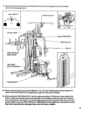
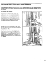
... move smoothly, locate and correct the problem before using the PROFORM 970 CI, test the cables and pulleys. Before using the PROFORM 970 Cl.MPORTANT: If the cables are properly tightened. Pull the end of this owner's manual. 53. Move the press arm, butterfly arms and leg lever a few times to make sure that all remaining parts will be permanently damaged when used with heavy weights. 19 "BUTTERFLY" "HIGH PULLEY" "PRESS ARM" "VKR VERTICAL KNEE RAISE" "LEG CURL LEG...
... move smoothly, locate and correct the problem before using the PROFORM 970 CI, test the cables and pulleys. Before using the PROFORM 970 Cl.MPORTANT: If the cables are properly tightened. Pull the end of this owner's manual. 53. Move the press arm, butterfly arms and leg lever a few times to make sure that all remaining parts will be permanently damaged when used with heavy weights. 19 "BUTTERFLY" "HIGH PULLEY" "PRESS ARM" "VKR VERTICAL KNEE RAISE" "LEG CURL LEG...

English Manual
Page 20
... EXERCISE GUIDE accompanying this owner's manual to see how the PROFORM 970 CI should be adjusted for each component of the PROFORM 970 CI can be set up to a maximum of 150 pounds, in the Adjuster. 20 70 Storage Hole 71 0 0 88 61 0 . 43 0 CHANGING THE WEIGHT SETTING The weight setting can be adjusted. Pivot the Press Arm forward or backward, and insert the 10 3/46 Pin through the indicated hole in the Leg...
... EXERCISE GUIDE accompanying this owner's manual to see how the PROFORM 970 CI should be adjusted for each component of the PROFORM 970 CI can be set up to a maximum of 150 pounds, in the Adjuster. 20 70 Storage Hole 71 0 0 88 61 0 . 43 0 CHANGING THE WEIGHT SETTING The weight setting can be adjusted. Pivot the Press Arm forward or backward, and insert the 10 3/46 Pin through the indicated hole in the Leg...
English Manual
Page 21
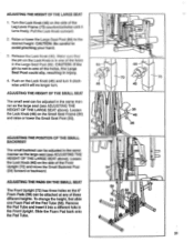
...) can be attached at any of the holes, the Large Seat Post could slip, resulting In Injury. 4. CAUTION: If the pin Is not in the Front Upright. Remove the Pad Tube and insert it will no longer turn. ADJUSTING THE HEIGHT OF THE SMALL SEAT The small seat can be adjusted in the same manner as the large seat (see ADJUSTING THE HEIGHT...
...) can be attached at any of the holes, the Large Seat Post could slip, resulting In Injury. 4. CAUTION: If the pin Is not in the Front Upright. Remove the Pad Tube and insert it will no longer turn. ADJUSTING THE HEIGHT OF THE SMALL SEAT The small seat can be adjusted in the same manner as the large seat (see ADJUSTING THE HEIGHT...
English Manual
Page 22
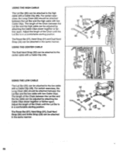
... manner. 22 The length of the Chain until the Lat Bar is in a comfortable starting position. For certain exercises, the Long Chain (82) should be attached between the Lat Bar and the high cable can be adjusted by attaching the Cable Clips closer together or farther apart. USING THE CENTER CABLE The Dual Hand Strap (32) can be attached to the center cable with a Cable Clip (48).
... manner. 22 The length of the Chain until the Lat Bar is in a comfortable starting position. For certain exercises, the Long Chain (82) should be attached between the Lat Bar and the high cable can be adjusted by attaching the Cable Clips closer together or farther apart. USING THE CENTER CABLE The Dual Hand Strap (32) can be attached to the center cable with a Cable Clip (48).
English Manual
Page 23
... the "U" Bracket (52) and the Cable Clip (48) by turning the bolt, refer to thread it farther into the Weight Selector (57) until about half the threads are tight. TROUBLE-SHOOTING AND MAINTENANCE Inspect and tighten all parts of Cable #1 (91). Turn the bolt clockwise to the instructions below. To tighten the cables, find the Short Chain (81). Replace any worn parts immediately. Next, find the...
... the "U" Bracket (52) and the Cable Clip (48) by turning the bolt, refer to thread it farther into the Weight Selector (57) until about half the threads are tight. TROUBLE-SHOOTING AND MAINTENANCE Inspect and tighten all parts of Cable #1 (91). Turn the bolt clockwise to the instructions below. To tighten the cables, find the Short Chain (81). Replace any worn parts immediately. Next, find the...
English Manual
Page 24
... SERIAL NUMBER of the product (see the PART LIST/EXPLODED DRAWING accompanying this manual). 4. The KEY NUMBER and DESCRIPTION of the part(s) (see the front cover of this manual). This warranty does not extend to any product or damage to a product caused by or attributable to give the following information: 1. The NAME of the product (PF897030). 2. PROFORM's obligat.'Rn\ under normal use and service conditions...
... SERIAL NUMBER of the product (see the PART LIST/EXPLODED DRAWING accompanying this manual). 4. The KEY NUMBER and DESCRIPTION of the part(s) (see the front cover of this manual). This warranty does not extend to any product or damage to a product caused by or attributable to give the following information: 1. The NAME of the product (PF897030). 2. PROFORM's obligat.'Rn\ under normal use and service conditions...

