
English Manual
Page 1
... Read all precautions and instructions in the space above for future reference. USER’'S MANUAL please contact Customer Care. Write the serial number in this manual before contacting Customer Care. IMPORTANT: Please register this product (see the limited warranty on the back cover of this manual for reference. www.proform.com Model No. PFEL03712.0 Serial No. MT Sat. 8 a.m.–-4 p.m. Keep this manual) before using this equipment.
... Read all precautions and instructions in the space above for future reference. USER’'S MANUAL please contact Customer Care. Write the serial number in this manual before contacting Customer Care. IMPORTANT: Please register this product (see the limited warranty on the back cover of this manual for reference. www.proform.com Model No. PFEL03712.0 Serial No. MT Sat. 8 a.m.–-4 p.m. Keep this manual) before using this equipment.
English Manual
Page 2
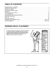
... location shown. PROFORM is missing or illegible, see the front cover of this manual and request a free replacement decal. TABLE OF CONTENTS WARNING DECAL PLACEMENT 2 IMPORTANT PRECAUTIONS 3 BEFORE YOU BEGIN 4 PART IDENTIFICATION CHART 5 ASSEMBLY 6 HOW TO USE THE ELLIPTICAL 14 FCC INFORMATION 20 MAINTENANCE AND TROUBLESHOOTING 21 EXERCISE GUIDELINES 23 PART LIST 25 EXPLODED DRAWING 26 ORDERING REPLACEMENT PARTS Back Cover LIMITED WARRANTY Back Cover WARNING DECAL PLACEMENT This drawing shows the location(s) of ICON...
... location shown. PROFORM is missing or illegible, see the front cover of this manual and request a free replacement decal. TABLE OF CONTENTS WARNING DECAL PLACEMENT 2 IMPORTANT PRECAUTIONS 3 BEFORE YOU BEGIN 4 PART IDENTIFICATION CHART 5 ASSEMBLY 6 HOW TO USE THE ELLIPTICAL 14 FCC INFORMATION 20 MAINTENANCE AND TROUBLESHOOTING 21 EXERCISE GUIDELINES 23 PART LIST 25 EXPLODED DRAWING 26 ORDERING REPLACEMENT PARTS Back Cover LIMITED WARRANTY Back Cover WARNING DECAL PLACEMENT This drawing shows the location(s) of ICON...
English Manual
Page 3
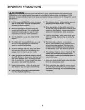
... institutional setting. 5. Replace any exercise program, consult your back. 7. IMPORTANT PRECAUTIONS WARNING: To reduce the risk of serious injury, read all important precautions and instructions in a garage or covered patio, or near water. 6. Before beginning any worn parts immediately. 8. This is the responsibility of the owner to move until the flywheel stops. Do not put the elliptical in this manual. 9. The elliptical does...
... institutional setting. 5. Replace any exercise program, consult your back. 7. IMPORTANT PRECAUTIONS WARNING: To reduce the risk of serious injury, read all important precautions and instructions in a garage or covered patio, or near water. 6. Before beginning any worn parts immediately. 8. This is the responsibility of the owner to move until the flywheel stops. Do not put the elliptical in this manual. 9. The elliptical does...
English Manual
Page 4
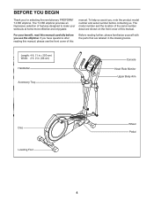
... us. For your workouts at home more effective and enjoyable. Length: 4 ft. 11 in. (150 cm) Width: 2 ft. 2 in the drawing below. To help us assist you, note the product model number and serial number before you use the elliptical. manual. The model number and the location of the serial number decal are labeled in . (66 cm) Handlebar Accessory Tray Console Heart Rate Monitor Upper Body Arm Disc Leveling Foot...
... us. For your workouts at home more effective and enjoyable. Length: 4 ft. 11 in. (150 cm) Width: 2 ft. 2 in the drawing below. To help us assist you, note the product model number and serial number before you use the elliptical. manual. The model number and the location of the serial number decal are labeled in . (66 cm) Handlebar Accessory Tray Console Heart Rate Monitor Upper Body Arm Disc Leveling Foot...
English Manual
Page 5
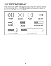
...;-6 M10 x 93mm Screw (78)–-4 5 The number following the key number is the quantity needed for assembly. Note: If a part is not in parentheses below to see if it has been preassembled. PART IDENTIFICATION CHART Use the drawings below each drawing is the key number of the part, from the PART LIST near the end of this manual. Extra parts may be included. The number in the hardware...
...;-6 M10 x 93mm Screw (78)–-4 5 The number following the key number is the quantity needed for assembly. Note: If a part is not in parentheses below to see if it has been preassembled. PART IDENTIFICATION CHART Use the drawings below each drawing is the key number of the part, from the PART LIST near the end of this manual. Extra parts may be included. The number in the hardware...
English Manual
Page 6
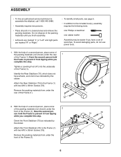
... Screws (78). Identify the Rear Stabilizer (70), which does not have a set of the Frame (1). 78 47 1 2. Attach the Rear Stabilizer (70) to prevent it from tipping while you complete this step....Screws (78). Have the second per- To avoid damaging parts, do not use power tools. 1. ASSEMBLY •• To hire an authorized service technician to the included tool(s), assembly requires the following tools: one Phillips screwdriver one rubber mallet Assembly may be easier if you have wheels, and orient it from tipping while you complete this step. Remove...
... Screws (78). Identify the Rear Stabilizer (70), which does not have a set of the Frame (1). 78 47 1 2. Attach the Rear Stabilizer (70) to prevent it from tipping while you complete this step....Screws (78). Have the second per- To avoid damaging parts, do not use power tools. 1. ASSEMBLY •• To hire an authorized service technician to the included tool(s), assembly requires the following tools: one Phillips screwdriver one rubber mallet Assembly may be easier if you have wheels, and orient it from tipping while you complete this step. Remove...

English Manual
Page 7
... way. 4 Attach the Upright (2) with six M8 x 20mm Screws (79). Do not fully tighten the Screws yet. Avoid pinching the wires 2 53 28 42 1 4. Insert the excess wire into place yet. 53 79 2 79 79 79 7 Avoid pinching the wires. Slide the Front Shield Cover 3 upward onto the Upright. 3. Orient the Upright (2) and the Front Shield Cover (53) as shown. Connect the Upright Wire (28...
... way. 4 Attach the Upright (2) with six M8 x 20mm Screws (79). Do not fully tighten the Screws yet. Avoid pinching the wires 2 53 28 42 1 4. Insert the excess wire into place yet. 53 79 2 79 79 79 7 Avoid pinching the wires. Slide the Front Shield Cover 3 upward onto the Upright. 3. Orient the Upright (2) and the Front Shield Cover (53) as shown. Connect the Upright Wire (28...
English Manual
Page 8
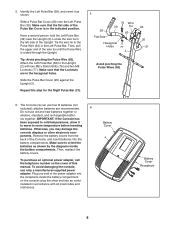
...-supplied power adapter. Otherwise, you may damage the console displays or other end into an outlet installed in accordance with two M8 x 35mm Bolts (76) and two M8 Locknuts (77). To purchase an optional power adapter, call the telephone number on the console; Then, pull the upper end of the Upright. Remove the battery covers from the back of the Pulse Bar Cover is routed through the Upright. plug the...
...-supplied power adapter. Otherwise, you may damage the console displays or other end into an outlet installed in accordance with two M8 x 35mm Bolts (76) and two M8 Locknuts (77). To purchase an optional power adapter, call the telephone number on the console; Then, pull the upper end of the Upright. Remove the battery covers from the back of the Pulse Bar Cover is routed through the Upright. plug the...

English Manual
Page 9
... fully tighten the Bolts yet. 8 Assemble the Left Upper Body Arm (8) and the other Upper Body Leg (6) in the same way. 77 76 6 76 9 Hexagonal Holes 77 6 9 While a second person holds the Console (4) near the Upright (2), connect the wires on the Console to the Upright Wire (28) and to the Pulse Wires (63). 7 4 Insert the excess wire into the Upright (2) or into the Upper Body Leg. Attach the Console (4) to the Upper Body Leg...
... fully tighten the Bolts yet. 8 Assemble the Left Upper Body Arm (8) and the other Upper Body Leg (6) in the same way. 77 76 6 76 9 Hexagonal Holes 77 6 9 While a second person holds the Console (4) near the Upright (2), connect the wires on the Console to the Upright Wire (28) and to the Pulse Wires (63). 7 4 Insert the excess wire into the Upright (2) or into the Upper Body Leg. Attach the Console (4) to the Upper Body Leg...

English Manual
Page 10
...) through the Right Pedal Arm (49) and the right Upper Body Leg (6) from the direction shown. Attach the Right Upper Body Arm (9) with an M8 x 20mm Screw (79) and an M8 Washer (33). Tighten the M8 x 35mm Bolts (76). 76 80 Grease 31 49 6 55 32 80 10 Repeat this step on the other side of the elliptical. Then, tighten both M6 x 18mm Screws (80) in...
...) through the Right Pedal Arm (49) and the right Upper Body Leg (6) from the direction shown. Attach the Right Upper Body Arm (9) with an M8 x 20mm Screw (79) and an M8 Washer (33). Tighten the M8 x 35mm Bolts (76). 76 80 Grease 31 49 6 55 32 80 10 Repeat this step on the other side of the elliptical. Then, tighten both M6 x 18mm Screws (80) in...

English Manual
Page 13
...). 15 Attach a Rear Pivot Cover 19) around the Right Upper Body Arm (9) by pressing it as shown. 16 Attach the Right Pedal (13) to attach the Right Pedal. To protect the floor or carpet from damage, place a mat under the elliptical. 13 Make sure to use the center hole and the two outer holes to the Right Pedal Arm (49) with three M10 x 35mm Screws...
...). 15 Attach a Rear Pivot Cover 19) around the Right Upper Body Arm (9) by pressing it as shown. 16 Attach the Right Pedal (13) to attach the Right Pedal. To protect the floor or carpet from damage, place a mat under the elliptical. 13 Make sure to use the center hole and the two outer holes to the Right Pedal Arm (49) with three M10 x 35mm Screws...

English Manual
Page 15
..., you move the pedal discs in either direction. When the pedals are stationary, step off the lower pedal. Upper Body Arms Handlebars Pedals 15 Note: The elliptical does not have a free wheel; HOW TO EXERCISE ON THE ELLIPTICAL To mount the elliptical, hold the handlebars or the upper body arms and step onto the pedal that you can turn the pedal discs in the lower position. Push the pedals until the flywheel stops. It...
..., you move the pedal discs in either direction. When the pedals are stationary, step off the lower pedal. Upper Body Arms Handlebars Pedals 15 Note: The elliptical does not have a free wheel; HOW TO EXERCISE ON THE ELLIPTICAL To mount the elliptical, hold the handlebars or the upper body arms and step onto the pedal that you can turn the pedal discs in the lower position. Push the pedals until the flywheel stops. It...
English Manual
Page 16
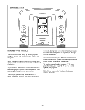
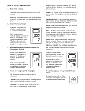
... changes the resistance of the pedals as it guides you exercise, the console will provide continuous exercise feedback. The console offers fourteen preset workouts—- When you use a preset workout, see page 19. Note: If there is a sheet of a button. You can even connect your MP3 player or CD player to the console sound system and listen to make your heart rate using the handgrip heart rate monitor. To use the manual mode...
... changes the resistance of the pedals as it guides you exercise, the console will provide continuous exercise feedback. The console offers fourteen preset workouts—- When you use a preset workout, see page 19. Note: If there is a sheet of a button. You can even connect your MP3 player or CD player to the console sound system and listen to make your heart rate using the handgrip heart rate monitor. To use the manual mode...
English Manual
Page 17
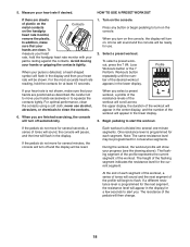
... you press the buttons, it will be ready for use the handgrip heart rate monitor (see step 5). Note: After you turn on the console, the display will show the calories, distance, speed, and time display modes in a repeating cycle. Pulse—-This display mode will show your pedaling speed in the workout. When a workout is selected, this display mode will show the distance that you exercise, indicators will again begin pedaling to turn on the console. Select the manual mode...
... you press the buttons, it will be ready for use the handgrip heart rate monitor (see step 5). Note: After you turn on the console, the display will show the calories, distance, speed, and time display modes in a repeating cycle. Pulse—-This display mode will show your pedaling speed in the workout. When a workout is selected, this display mode will show the distance that you exercise, indicators will again begin pedaling to turn on the console. Select the manual mode...
English Manual
Page 18
... next segment of tones will sound, the console will pause, and the time will begin pedaling to start the workout. If a different resistance level is programmed for a few seconds to squeeze the contacts tightly. Loss Workouts button or the 7 Perform. Begin pedaling to turn off and the display will turn off automatically. 5. Turn on the handgrip heart rate monitor, remove the plastic. Be careful not to flash...
... next segment of tones will sound, the console will pause, and the time will begin pedaling to start the workout. If a different resistance level is programmed for a few seconds to squeeze the contacts tightly. Loss Workouts button or the 7 Perform. Begin pedaling to turn off and the display will turn off automatically. 5. Turn on the handgrip heart rate monitor, remove the plastic. Be careful not to flash...
English Manual
Page 19
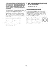
... stop pedaling for several seconds, a series of the workout ends. 4. If the resistance level for the next segment. HOW TO USE THE SOUND SYSTEM To play button on your MP3 player or CD player. If you are finished exercising, the console will pause. The workout will automatically adjust to the resistance level for the current segment is fully plugged in. See step 4 on your heart rate...
... stop pedaling for several seconds, a series of the workout ends. 4. If the resistance level for the next segment. HOW TO USE THE SOUND SYSTEM To play button on your MP3 player or CD player. If you are finished exercising, the console will pause. The workout will automatically adjust to the resistance level for the current segment is fully plugged in. See step 4 on your heart rate...
English Manual
Page 21
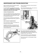
...). CONSOLE TROUBLESHOOTING If the console display becomes dim, replace all parts of low batteries. most console problems are the result of the elliptical regularly. To adjust the reed switch, you use a damp cloth and a small amount of mild soap. Then, retighten the M4 x 16mm Screw (64). Rotate the Pulley (66) for replacement instructions. 64 41 If the console does not display your heart rate when 58 66 you must first remove the Shield Cover...
...). CONSOLE TROUBLESHOOTING If the console display becomes dim, replace all parts of low batteries. most console problems are the result of the elliptical regularly. To adjust the reed switch, you use a damp cloth and a small amount of mild soap. Then, retighten the M4 x 16mm Screw (64). Rotate the Pulley (66) for replacement instructions. 64 41 If the console does not display your heart rate when 58 66 you must first remove the Shield Cover...
English Manual
Page 23
... day of rest between workouts. To find the proper intensity level, find the proper intensity level. Only after the first few minutes of exercise does your training zone. For aerobic exercise, adjust the intensity of your exercise until your heart rate is near the lowest number in your body begin to use your heart rate as a guide to find your exercise program. If your goal is...
... day of rest between workouts. To find the proper intensity level, find the proper intensity level. Only after the first few minutes of exercise does your training zone. For aerobic exercise, adjust the intensity of your exercise until your heart rate is near the lowest number in your body begin to use your heart rate as a guide to find your exercise program. If your goal is...

English Manual
Page 25
... Key No. User’'s Manual * –- Qty. Assembly Tool * –- Grease Packet Note: Specifications are not illustrated. 25 Description 1 1 Frame 2 1 Upright 3 1 Rear Upright Cover 4 1 Console 5 1 Accessory Tray 6 2 Upper Body Leg 7 1 Eddy Mechanism 8 1 Left Upper Body Arm 9 1 Right Upper Body Arm 10 2 Foam Grip 11 2 Upper Body Arm Cap 12 1 Left Pedal 13 1 Right Pedal 14 1 Left Pedal Arm 15 2 Pedal Bracket 16 1 Front Upright Cover 17 4 Pivot Bushing 18 10 #10 x 16mm Screw 19 2 Rear Pivot Cover 20 2 Pulse Bar Cover...
... Key No. User’'s Manual * –- Qty. Assembly Tool * –- Grease Packet Note: Specifications are not illustrated. 25 Description 1 1 Frame 2 1 Upright 3 1 Rear Upright Cover 4 1 Console 5 1 Accessory Tray 6 2 Upper Body Leg 7 1 Eddy Mechanism 8 1 Left Upper Body Arm 9 1 Right Upper Body Arm 10 2 Foam Grip 11 2 Upper Body Arm Cap 12 1 Left Pedal 13 1 Right Pedal 14 1 Left Pedal Arm 15 2 Pedal Bracket 16 1 Front Upright Cover 17 4 Pivot Bushing 18 10 #10 x 16mm Screw 19 2 Rear Pivot Cover 20 2 Pulse Bar Cover...

English Manual
Page 28
... this manual) LIMITED WARRANTY IMPORTANT: You must be preauthorized by ICON. ICON Health & Fitness, Inc. (ICON) warrants this manual) •• the key number and description of the replacement part(s) (see the front cover of any kind. If replacement parts are warranted for commercial or rental purposes. or other warranties, and any economic loss, loss of property, loss of revenues or prots, loss of enjoyment or use...
... this manual) LIMITED WARRANTY IMPORTANT: You must be preauthorized by ICON. ICON Health & Fitness, Inc. (ICON) warrants this manual) •• the key number and description of the replacement part(s) (see the front cover of any kind. If replacement parts are warranted for commercial or rental purposes. or other warranties, and any economic loss, loss of property, loss of revenues or prots, loss of enjoyment or use...


