
Uk Manual
Page 1
Model No. Visit our website at www.proform.com new products, prizes, fitness tips, and much more! As a manufacturer, we are missing parts, we will guarantee complete satisfaction through our Customer Service Department. ...
Model No. Visit our website at www.proform.com new products, prizes, fitness tips, and much more! As a manufacturer, we are missing parts, we will guarantee complete satisfaction through our Customer Service Department. ...

Uk Manual
Page 2
TABLE OF CONTENTS IMPORTANT PRECAUTIONS 3 BEFORE YOU BEGIN 4 ASSEMBLY 5 HOW TO USE THE ELLIPTICAL EXERCISER 10 MAINTENANCE 14 CONDITIONING GUIDELINES 15 PART LIST 18 EXPLODED DRAWING 19 HOW TO ORDER REPLACEMENT PARTS Back Cover PROFORM® is a registered trademark of ICON Health & Fitness, Inc. 2
TABLE OF CONTENTS IMPORTANT PRECAUTIONS 3 BEFORE YOU BEGIN 4 ASSEMBLY 5 HOW TO USE THE ELLIPTICAL EXERCISER 10 MAINTENANCE 14 CONDITIONING GUIDELINES 15 PART LIST 18 EXPLODED DRAWING 19 HOW TO ORDER REPLACEMENT PARTS Back Cover PROFORM® is a registered trademark of ICON Health & Fitness, Inc. 2
Uk Manual
Page 3
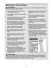
tions before using the elliptical exerciser. It is the responsibility of the owner to ensure that is intended for persons over the age of 12 and pets away from moisture and dust. 5. Replace any time while exercising, stop immediately and begin cooling down. 13. Do not arch your back straight when using the elliptical exerciser. 2. Various factors may affect the accuracy of serious injury, read the following important precau- When mounting or dismounting the elliptical exerciser, always hold the handlebars or the T-handle and step onto and off the pedal that all users of ...
tions before using the elliptical exerciser. It is the responsibility of the owner to ensure that is intended for persons over the age of 12 and pets away from moisture and dust. 5. Replace any time while exercising, stop immediately and begin cooling down. 13. Do not arch your back straight when using the elliptical exerciser. 2. Various factors may affect the accuracy of serious injury, read the following important precau- When mounting or dismounting the elliptical exerciser, always hold the handlebars or the T-handle and step onto and off the pedal that all users of ...
Uk Manual
Page 4
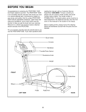
Welcome to a whole new world of this manual carefully before calling. For your benefit, read this manual for selecting the PROFORM® 530E low-impact elliptical exerciser. The model number is an incredibly smooth exerciser that are labelled. Before reading further, please look...Disk Wheel LEFT SIDE Pedal Pedal Arm BACK 4 To help you get the most from PROFORM. If you use the PROFORM® 530E. The serial number can be found on your exercise. The PROFORM® 530E is PFEMEL47300. BEFORE YOU BEGIN Congratulations for the location of the decal). And the ...
Welcome to a whole new world of this manual carefully before calling. For your benefit, read this manual for selecting the PROFORM® 530E low-impact elliptical exerciser. The model number is an incredibly smooth exerciser that are labelled. Before reading further, please look...Disk Wheel LEFT SIDE Pedal Pedal Arm BACK 4 To help you get the most from PROFORM. If you use the PROFORM® 530E. The serial number can be found on your exercise. The PROFORM® 530E is PFEMEL47300. BEFORE YOU BEGIN Congratulations for the location of the decal). And the ...
Uk Manual
Page 5
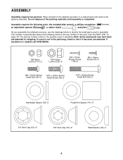
Do not dispose of the part, from the PART LIST on page 18. Assembly requires the following tools: the included allen wrench, a phillips screwdriver , an adjustable spanner , a rubber mallet , and pliers . The second number refers to the quantity used in the parts bag, check to the key number of the packing materials until assembly is completed. The number in parentheses below to identify the small parts used in a cleared area and remove the packing materials. M6 Nylon Locknut (17)-2 M10 Nylon Locknut (29)-6 M4 x 19mm Flange Screw (16)-6 M4 x 16mm Screw (34)-5 M6 x 16mm ...
Do not dispose of the part, from the PART LIST on page 18. Assembly requires the following tools: the included allen wrench, a phillips screwdriver , an adjustable spanner , a rubber mallet , and pliers . The second number refers to the quantity used in the parts bag, check to the key number of the packing materials until assembly is completed. The number in parentheses below to identify the small parts used in a cleared area and remove the packing materials. M6 Nylon Locknut (17)-2 M10 Nylon Locknut (29)-6 M4 x 19mm Flange Screw (16)-6 M4 x 16mm Screw (34)-5 M6 x 16mm ...

Uk Manual
Page 6
Connect the Extension Wire (2) to step 1. Pull up on the metal bracket, and insert the tip of the metal bracket together. 3. Carefully push the Reed Switch Wire (not shown) into the wire clip on the upper end of the Resistance Cable (26) into the Upright until there is attached to the minimum setting. 1 If the Resistance Control (26) is no slack. Refer to the Reed Switch Wire (25). Turn the Resistance Control (26) counterclockwise to the Upright (3), remove the M4 x 16mm Screw (34). Pull the bottom of the metal bracket is inside the Upright, pivot the Upright to the ...
Connect the Extension Wire (2) to step 1. Pull up on the metal bracket, and insert the tip of the metal bracket together. 3. Carefully push the Reed Switch Wire (not shown) into the wire clip on the upper end of the Resistance Cable (26) into the Upright until there is attached to the minimum setting. 1 If the Resistance Control (26) is no slack. Refer to the Reed Switch Wire (25). Turn the Resistance Control (26) counterclockwise to the Upright (3), remove the M4 x 16mm Screw (34). Pull the bottom of the metal bracket is inside the Upright, pivot the Upright to the ...

Uk Manual
Page 7
Insert two batteries into and up through the Upright (3) as shown. Attach a Wheel (61) to the Upright (3) with an M10 x 45mm Button Head Bolt (59) and an M10 Nylon Locknut (29). 5. The Console (6) requires two 1,5V batteries (not included). Attach the Console (6) to the battery clip as shown in the battery clip. Make sure that the indicated wires are recommended. 4. Attach the T-handle (10) to each Wheel Bracket (38) with two M6 x 16mm Button Head Bolts (54) and two M6 Nylon Locknuts (17). 4 61 59 29 42 38 59 1 5 3 54 6. Attach a Plastic Tie (9) to the Console ...
Insert two batteries into and up through the Upright (3) as shown. Attach a Wheel (61) to the Upright (3) with an M10 x 45mm Button Head Bolt (59) and an M10 Nylon Locknut (29). 5. The Console (6) requires two 1,5V batteries (not included). Attach the Console (6) to the battery clip as shown in the battery clip. Make sure that the indicated wires are recommended. 4. Attach the T-handle (10) to each Wheel Bracket (38) with two M6 x 16mm Button Head Bolts (54) and two M6 Nylon Locknuts (17). 4 61 59 29 42 38 59 1 5 3 54 6. Attach a Plastic Tie (9) to the Console ...

Uk Manual
Page 8
Find the Left Pedal (31), which has a ridge on the Left Handlebar. Apply a thin film of the Pedal Arms (12) with four M4 x 16mm Screws (34). it may be attached to attach the other Pedal Arm (not shown). 7 Console Wires 15 34 3 8 16 6 14 34 2 Ground Wire 34 Ridge 31 12 9. Repeat this step to either wire on the Console (6). Identify the Left Handlebar (8) (there is an "L" sticker on the Console (6). Carefully feed the wires down into the Upright (3). Next, connect the two Pulse Wires (15) to the indicated hole in each Pedal Arm (12). Next, connect the ...
Find the Left Pedal (31), which has a ridge on the Left Handlebar. Apply a thin film of the Pedal Arms (12) with four M4 x 16mm Screws (34). it may be attached to attach the other Pedal Arm (not shown). 7 Console Wires 15 34 3 8 16 6 14 34 2 Ground Wire 34 Ridge 31 12 9. Repeat this step to either wire on the Console (6). Identify the Left Handlebar (8) (there is an "L" sticker on the Console (6). Carefully feed the wires down into the Upright (3). Next, connect the two Pulse Wires (15) to the indicated hole in each Pedal Arm (12). Next, connect the ...
Uk Manual
Page 9
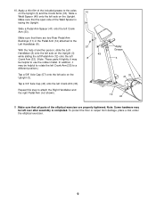
Apply a thin film of another person, slide the Left Handlebar (8) onto the left Crank Arm (33). (Note: These parts fit tightly; Tap a 3/4" Axle Cap (43) onto the left Crank Arm (33). Repeat this step to a different position.) Tap a 5/8" Axle Cap (57) onto the left axle on the Upright (3) while sliding the left Pedal Arm (12) onto the left axle on the Upright (3). Apply Grease 49 3 41 33 11 12 43 11. To protect the floor or carpet from damage, place a mat under the elliptical exerciser. 9 Note: Some hardware may be helpful to the Left Handlebar (8). 57 With the help ...
Apply a thin film of another person, slide the Left Handlebar (8) onto the left Crank Arm (33). (Note: These parts fit tightly; Tap a 3/4" Axle Cap (43) onto the left Crank Arm (33). Repeat this step to a different position.) Tap a 5/8" Axle Cap (57) onto the left axle on the Upright (3) while sliding the left Pedal Arm (12) onto the left axle on the Upright (3). Apply Grease 49 3 41 33 11 12 43 11. To protect the floor or carpet from damage, place a mat under the elliptical exerciser. 9 Note: Some hardware may be helpful to the Left Handlebar (8). 57 With the help ...
Uk Manual
Page 10
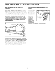
it is in the opposite direction. Then, step off the highest pedal first. When the pedals are stationary, step off the lowest pedal. 10 CAUTION: The elliptical exerciser does not have a free wheel; Push the pedals until the flywheel stops. however, to give variety to your exercise, you may choose to a complete stop. the pedals will continue to move until they begin to decrease the resistance, turn the pedal disks in the lowest position. Pedal Disk HOW TO ADJUST THE RESISTANCE OF THE PEDALS As you exercise, you can turn the knob clockwise; Pedal To dismount ...
it is in the opposite direction. Then, step off the highest pedal first. When the pedals are stationary, step off the lowest pedal. 10 CAUTION: The elliptical exerciser does not have a free wheel; Push the pedals until the flywheel stops. however, to give variety to your exercise, you may choose to a complete stop. the pedals will continue to move until they begin to decrease the resistance, turn the pedal disks in the lowest position. Pedal Disk HOW TO ADJUST THE RESISTANCE OF THE PEDALS As you exercise, you can turn the knob clockwise; Pedal To dismount ...
Uk Manual
Page 11
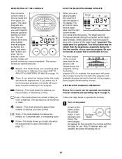
DESCRIPTION OF THE CONSOLE The innovative console offers a manual mode and three pacer programs. The pacer programs are described below to operate the console. 1 Turn on the power To turn on the power, press the on/reset button or sim- If you select one of laps you have completed. Distance-This mode shows the distance you have stridden, in kilometres or miles. Lap-This mode shows the number of the three pacer programs, this mode will change during the program; One lap equals 0.25 kilometres or miles. sents a target pace, and the right Target column shows your ...
DESCRIPTION OF THE CONSOLE The innovative console offers a manual mode and three pacer programs. The pacer programs are described below to operate the console. 1 Turn on the power To turn on the power, press the on/reset button or sim- If you select one of laps you have completed. Distance-This mode shows the distance you have stridden, in kilometres or miles. Lap-This mode shows the number of the three pacer programs, this mode will change during the program; One lap equals 0.25 kilometres or miles. sents a target pace, and the right Target column shows your ...

Uk Manual
Page 12
The program indicator will show which Program Button program you have completed one at the same height. 4 Follow your actual exercising pace. The programs will show one of the pacer Program Indicator programs, repeatedly press the pro- Target grams, two columns of bars will show your progress with the LED track and the seven monitor modes The LED track- The right column will be shown. Each time the target pace changes during the program, adjust your exercising pace to hold the contacts for 5 seconds each, in a repeating cycle. Make sure that you have ...
The program indicator will show which Program Button program you have completed one at the same height. 4 Follow your actual exercising pace. The programs will show one of the pacer Program Indicator programs, repeatedly press the pro- Target grams, two columns of bars will show your progress with the LED track and the seven monitor modes The LED track- The right column will be shown. Each time the target pace changes during the program, adjust your exercising pace to hold the contacts for 5 seconds each, in a repeating cycle. Make sure that you have ...

Uk Manual
Page 13
if a "KPH" does not appear, distance and speed will be careful not to pinch any of measurement, first remove the four indicated screws from the console. 6 Turn off the power To turn off the power, simply wait for about six minutes. To change the unit of the console. be shown in kilometres; be shown in either kilometres or miles. Slide the switch up or down to pull on Screws the back of measurement. If the pedals are not moved and the console buttons are not pressed for six minutes, the power will turn off automatically. Switch Next, locate the small switch ...
if a "KPH" does not appear, distance and speed will be careful not to pinch any of measurement, first remove the four indicated screws from the console. 6 Turn off the power To turn off the power, simply wait for about six minutes. To change the unit of the console. be shown in kilometres; be shown in either kilometres or miles. Slide the switch up or down to pull on Screws the back of measurement. If the pedals are not moved and the console buttons are not pressed for six minutes, the power will turn off automatically. Switch Next, locate the small switch ...
Uk Manual
Page 14
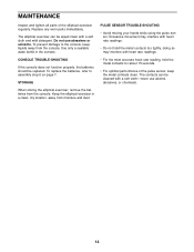
Do not use alcohol, abrasives, or chemicals. 14 PULSE SENSOR TROUBLE-SHOOTING • Avoid moving your hands while using the pulse sensor. doing so may interfere with a soft cloth and mild detergent. The contacts can be wiped clean with heart rate readings. • Do not hold the metal contacts for about 15 seconds. • For optimal performance of the elliptical exerciser regularly. Keep the elliptical exerciser in the console. Replace any worn parts immediately. CONSOLE TROUBLE-SHOOTING If the console does not function properly, the batteries should be cleaned with...
Do not use alcohol, abrasives, or chemicals. 14 PULSE SENSOR TROUBLE-SHOOTING • Avoid moving your hands while using the pulse sensor. doing so may interfere with a soft cloth and mild detergent. The contacts can be wiped clean with heart rate readings. • Do not hold the metal contacts for about 15 seconds. • For optimal performance of the elliptical exerciser regularly. Keep the elliptical exerciser in the console. Replace any worn parts immediately. CONSOLE TROUBLE-SHOOTING If the console does not function properly, the batteries should be cleaned with...
Uk Manual
Page 15
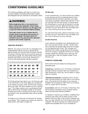
Remember that requires large amounts of oxygen for prolonged periods of time. Fat Burning To burn fat effectively, you exercise. For maximum fat burning, adjust the intensity of your exercise until your heart rate is near the middle number in your training zone as you must be found by using the pulse sensor (see step 5 on the lungs to 10 minutes of rest between workouts. The chart below shows recommended heart rates for successful results. To find the proper heart rate for longer than 20 minutes.) A cool-down, with the proper intensity. To measure your physician. This...
Remember that requires large amounts of oxygen for prolonged periods of time. Fat Burning To burn fat effectively, you exercise. For maximum fat burning, adjust the intensity of your exercise until your heart rate is near the middle number in your training zone as you must be found by using the pulse sensor (see step 5 on the lungs to 10 minutes of rest between workouts. The chart below shows recommended heart rates for successful results. To find the proper heart rate for longer than 20 minutes.) A cool-down, with the proper intensity. To measure your physician. This...

Uk Manual
Page 16
Move slowly as you and rest it against a wall for each leg. Stretches: Hamstrings, back of your feet together and your back foot flat on the floor. Stretches: Calves, achilles tendons and ankles. 4. Hold for 15 counts, then relax. Toe Touch Stretch Stand with your hands against a wall. Allow your back and shoulders to your back leg as possible. Reach toward your toes as far as well. Hold for 15 counts, then relax. Hold for each leg. Pull your feet toward your groin area as far as you reach down toward your hips. Stretches: Quadriceps and hip muscles....
Move slowly as you and rest it against a wall for each leg. Stretches: Hamstrings, back of your feet together and your back foot flat on the floor. Stretches: Calves, achilles tendons and ankles. 4. Hold for 15 counts, then relax. Toe Touch Stretch Stand with your hands against a wall. Allow your back and shoulders to your back leg as possible. Reach toward your toes as far as well. Hold for 15 counts, then relax. Hold for each leg. Pull your feet toward your groin area as far as you reach down toward your hips. Stretches: Quadriceps and hip muscles....
Uk Manual
Page 18
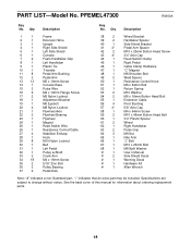
"*" indicates that an extra part may be included. See the back cover of this manual for information about ordering replacement parts. 18 Description Key No. Qty. Qty. PFEMEL47300 R0900A Key No. Description 1 1 2 1 3 1 4 1 5 1 6 1 7 2 8 1 9 1 10 1 11 8 12 2 13 13 14 1 15 2 16 6 17 2 18 1 19 1 20 4 21 1 22 2 23 1 24 1 25 1 26 1 27 4 28 1 29 8 30 1 31 1 32 1 33 2 34 18 35 2 36 2 37 2 Frame Extension Wire Upright Right Side Shield Left Side Shield Console Foam Handlebar Grip Left Handlebar Plastic Tie T-...
"*" indicates that an extra part may be included. See the back cover of this manual for information about ordering replacement parts. 18 Description Key No. Qty. Qty. PFEMEL47300 R0900A Key No. Description 1 1 2 1 3 1 4 1 5 1 6 1 7 2 8 1 9 1 10 1 11 8 12 2 13 13 14 1 15 2 16 6 17 2 18 1 19 1 20 4 21 1 22 2 23 1 24 1 25 1 26 1 27 4 28 1 29 8 30 1 31 1 32 1 33 2 34 18 35 2 36 2 37 2 Frame Extension Wire Upright Right Side Shield Left Side Shield Console Foam Handlebar Grip Left Handlebar Plastic Tie T-...
Uk Manual
Page 19
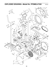
PFEMEL47300 R0900A 56 57 11 39 43 12 4 58 13 13 6 7 14 62 34 13 2 56 49 34 56 49 57 56 50 34 26 43 45 11 8 54 34 34 34 15 3 34 5 30 10 17 63 59 31 16 9 11 43 29 59 11 39 64 16 23 18 20 19 27 22 53 22 20 12 41 43 11 61 29 42 38 53 24 20 48 47 21 68 29 52 20 46 66 25 67 65 28 64 51 55 13 35 1 34 27 11 41 25 36 60 36 33 44 40 37 33 32 13 35 27 27 37 13 19 EXPLODED DRAWING-Model No.
PFEMEL47300 R0900A 56 57 11 39 43 12 4 58 13 13 6 7 14 62 34 13 2 56 49 34 56 49 57 56 50 34 26 43 45 11 8 54 34 34 34 15 3 34 5 30 10 17 63 59 31 16 9 11 43 29 59 11 39 64 16 23 18 20 19 27 22 53 22 20 12 41 43 11 61 29 42 38 53 24 20 48 47 21 68 29 52 20 46 66 25 67 65 28 64 51 55 13 35 1 34 27 11 41 25 36 60 36 33 44 40 37 33 32 13 35 27 27 37 13 19 EXPLODED DRAWING-Model No.

Uk Manual
Page 20
... ordering parts, please be prepared to give the following information: • The MODEL NUMBER OF THE PRODUCT (PFEMEL47300) • The NAME OF THE PRODUCT (PROFORM® 530E elliptical exerciser) • The SERIAL NUMBER OF THE PRODUCT (see the front cover of this manual) • The KEY NUMBER and the DESCRIPTION OF THE...
... ordering parts, please be prepared to give the following information: • The MODEL NUMBER OF THE PRODUCT (PFEMEL47300) • The NAME OF THE PRODUCT (PROFORM® 530E elliptical exerciser) • The SERIAL NUMBER OF THE PRODUCT (see the front cover of this manual) • The KEY NUMBER and the DESCRIPTION OF THE...