
English Manual
Page 1
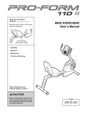
Write the serial number in this manual before using this manual for reference. Hoffman Estates, IL 60179 CAUTION Read all precautions and instructions in the space above for future reference. Model No. 831.21942.3 Serial No. Serial Number Decal (under frame) •• Assembly •• Operation •• Maintenance •• Part List and Drawing BIKE EXERCISER User’'s Manual Sears, Roebuck and Co. Keep this equipment.
Write the serial number in this manual before using this manual for reference. Hoffman Estates, IL 60179 CAUTION Read all precautions and instructions in the space above for future reference. Model No. 831.21942.3 Serial No. Serial Number Decal (under frame) •• Assembly •• Operation •• Maintenance •• Part List and Drawing BIKE EXERCISER User’'s Manual Sears, Roebuck and Co. Keep this equipment.
English Manual
Page 2
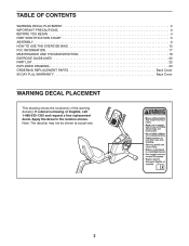
... request a free replacement decal. Note: The decal(s) may not be shown at actual size. 2 Apply the decal in the location shown. TABLE OF CONTENTS WARNING DECAL PLACEMENT 2 IMPORTANT PRECAUTIONS 3 BEFORE YOU BEGIN 4 PART IDENTIFICATION CHART 5 ASSEMBLY 6 HOW TO USE THE EXERCISE BIKE 12 FCC INFORMATION 17 MAINTENANCE AND TROUBLESHOOTING 18 EXERCISE GUIDELINES 20 PART LIST 22 EXPLODED DRAWING 23 ORDERING REPLACEMENT PARTS Back Cover 90 DAY FULL WARRANTY Back Cover WARNING...
... request a free replacement decal. Note: The decal(s) may not be shown at actual size. 2 Apply the decal in the location shown. TABLE OF CONTENTS WARNING DECAL PLACEMENT 2 IMPORTANT PRECAUTIONS 3 BEFORE YOU BEGIN 4 PART IDENTIFICATION CHART 5 ASSEMBLY 6 HOW TO USE THE EXERCISE BIKE 12 FCC INFORMATION 17 MAINTENANCE AND TROUBLESHOOTING 18 EXERCISE GUIDELINES 20 PART LIST 22 EXPLODED DRAWING 23 ORDERING REPLACEMENT PARTS Back Cover 90 DAY FULL WARRANTY Back Cover WARNING...
English Manual
Page 3
... pre-existing health problems. 9. This is intended only as described in this manual. 3. do not arch your pedaling speed in a controlled way. 14. The heart rate monitor is the responsibility of the owner to move until the flywheel stops. Reduce your back. 13. Wear appropriate clothes while exercising; It is not a medical device. Replace any exercise program, consult your physician. Always keep your exercise bike. The exercise bike does not...
... pre-existing health problems. 9. This is intended only as described in this manual. 3. do not arch your pedaling speed in a controlled way. 14. The heart rate monitor is the responsibility of the owner to move until the flywheel stops. Reduce your back. 13. Wear appropriate clothes while exercising; It is not a medical device. Replace any exercise program, consult your physician. Always keep your exercise bike. The exercise bike does not...
English Manual
Page 4
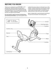
... location of the serial number decal are labeled in . (53 cm) Accessory Tray Backrest Seat Console Heart Rate Monitor Handlebar Pedal Wheel Handlebar Leveling Cap 4 The 110 R exercise bike provides a selection of features designed to make your benefit, read this manual. Cycling is an effective exercise for selecting the new PROFORM® 110 R exercise bike. To help us assist you for increasing cardiovascular fitness, building endurance, and toning the body...
... location of the serial number decal are labeled in . (53 cm) Accessory Tray Backrest Seat Console Heart Rate Monitor Handlebar Pedal Wheel Handlebar Leveling Cap 4 The 110 R exercise bike provides a selection of features designed to make your benefit, read this manual. Cycling is an effective exercise for selecting the new PROFORM® 110 R exercise bike. To help us assist you for increasing cardiovascular fitness, building endurance, and toning the body...
English Manual
Page 5
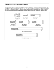
...;-4 M8 x 20mm Screw (55)–-12 M8 x 36mm Screw (26)–-3 M8 x 40mm Screw (58)–-2 M8 x 120mm Bolt (61)–-1 M10 x 80mm Screw (54)–-2 5 If a part is the key number of the part, from the PART LIST near the end of this manual. The number in the hardware kit, check to identify the small parts needed for assembly. The number following the key number is not in...
...;-4 M8 x 20mm Screw (55)–-12 M8 x 36mm Screw (26)–-3 M8 x 40mm Screw (58)–-2 M8 x 120mm Bolt (61)–-1 M10 x 80mm Screw (54)–-2 5 If a part is the key number of the part, from the PART LIST near the end of this manual. The number in the hardware kit, check to identify the small parts needed for assembly. The number following the key number is not in...
English Manual
Page 6
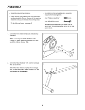
... materials. Orient the Rear Stabilizer (31) and the Carriage Rail (9) as indicated by the decal. 1 While a second person lifts the front of wrenches. Do 26 not tighten the Screws yet. 9 31 6 To avoid damaging parts, do not use power tools. 1. Do not dispose of the packing materials until you have a set of the Frame (1), attach the Front Stabilizer...
... materials. Orient the Rear Stabilizer (31) and the Carriage Rail (9) as indicated by the decal. 1 While a second person lifts the front of wrenches. Do 26 not tighten the Screws yet. 9 31 6 To avoid damaging parts, do not use power tools. 1. Do not dispose of the packing materials until you have a set of the Frame (1), attach the Front Stabilizer...
English Manual
Page 7
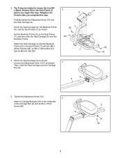
... (7) as shown. Orient the Seat Carriage (3) as shown. Attach the Seat Carriage (3) and the Backrest Frame (5) to the Seat Frame (7) with an M4 x 16mm Screw (56). 14 9 24 56 7 Partially tighten the Adjustment Knob (14) into the Seat Carriage (3). Set the Backrest Frame (5) on the Seat Frame (7), and then slide the Seat Carriage (3) onto the Backrest Frame. Tighten the Adjustment Knob (14). 5 Attach a Carriage Bumper (24...
... (7) as shown. Orient the Seat Carriage (3) as shown. Attach the Seat Carriage (3) and the Backrest Frame (5) to the Seat Frame (7) with an M4 x 16mm Screw (56). 14 9 24 56 7 Partially tighten the Adjustment Knob (14) into the Seat Carriage (3). Set the Backrest Frame (5) on the Seat Frame (7), and then slide the Seat Carriage (3) onto the Backrest Frame. Tighten the Adjustment Knob (14). 5 Attach a Carriage Bumper (24...
English Manual
Page 10
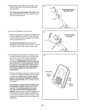
... the Upright and pull it to warm to orient the batteries as shown by the diagrams inside the battery compartment on the cover of the power adapter into an outlet installed in accordance with two M8 x 20mm Screws (55). 13 13 11 22 Avoid pinching the wires 2 55 14. Do not use only a manufacturer-supplied power adapter. plug the other electronic components. Orient the Console...
... the Upright and pull it to warm to orient the batteries as shown by the diagrams inside the battery compartment on the cover of the power adapter into an outlet installed in accordance with two M8 x 20mm Screws (55). 13 13 11 22 Avoid pinching the wires 2 55 14. Do not use only a manufacturer-supplied power adapter. plug the other electronic components. Orient the Console...
English Manual
Page 11
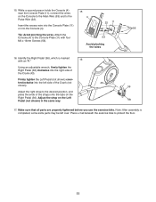
...). Adjust the right strap to the 4 Pulse Wire (22). 22 11 Insert the excess wire into the Console Plate (11) or into the right side of the Crank (43). Make sure that all parts are properly tightened before you use the exercise bike. Firmly tighten the Left Pedal (not shown) counterclockwise into the left over. While a second person holds the Console (4) near the Console Plate (11), connect...
...). Adjust the right strap to the 4 Pulse Wire (22). 22 11 Insert the excess wire into the Console Plate (11) or into the right side of the Crank (43). Make sure that all parts are properly tightened before you use the exercise bike. Firmly tighten the Left Pedal (not shown) counterclockwise into the left over. While a second person holds the Console (4) near the Console Plate (11), connect...
English Manual
Page 12
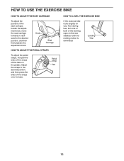
... HOW TO USE THE EXERCISE BIKE HOW TO ADJUST THE SEAT CARRIAGE To adjust the position of the straps onto the tabs. Adjust the straps to the desired position, and then press the ends of the seat carriage, loosen the adjustment knob, move the seat carriage forward or backward to the desired position, and then firmly tighten the adjustment knob. Knob Seat Carriage HOW TO ADJUST THE PEDAL STRAPS To adjust the pedal straps, first pull...
... HOW TO USE THE EXERCISE BIKE HOW TO ADJUST THE SEAT CARRIAGE To adjust the position of the straps onto the tabs. Adjust the straps to the desired position, and then press the ends of the seat carriage, loosen the adjustment knob, move the seat carriage forward or backward to the desired position, and then firmly tighten the adjustment knob. Knob Seat Carriage HOW TO ADJUST THE PEDAL STRAPS To adjust the pedal straps, first pull...
English Manual
Page 13
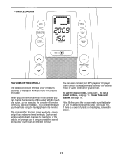
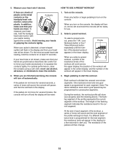
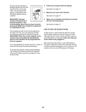
... timed workouts. You can even measure your heart rate using the console, make your MP3 player or CD player to the console sound system and listen to make sure that batteries are installed (see page 14. Note: Before using the handgrip heart rate monitor. To use the manual mode, see assembly step 14 on the display, remove the plastic. 13 To use the manual mode of a button. CONSOLE DIAGRAM FEATURES OF THE CONSOLE The advanced console offers...
... timed workouts. You can even measure your heart rate using the console, make your MP3 player or CD player to the console sound system and listen to make sure that batteries are installed (see page 14. Note: Before using the handgrip heart rate monitor. To use the manual mode, see assembly step 14 on the display, remove the plastic. 13 To use the manual mode of a button. CONSOLE DIAGRAM FEATURES OF THE CONSOLE The advanced console offers...
English Manual
Page 14
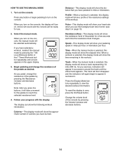
.... Press the Display Mode buttons repeatedly to zero, press the On/Reset button. To reset the display to view the desired workout information. Note: After you turn on . The display can show the following workout information: Calories—-This display mode will show the approximate number of the pedals as desired. Track—-When the manual mode is selected, this display mode will show a profile of the resistance settings of the pedals for use the handgrip heart rate monitor (see step 5 on...
.... Press the Display Mode buttons repeatedly to zero, press the On/Reset button. To reset the display to view the desired workout information. Note: After you turn on . The display can show the following workout information: Calories—-This display mode will show the approximate number of the pedals as desired. Track—-When the manual mode is selected, this display mode will show a profile of the resistance settings of the pedals for use the handgrip heart rate monitor (see step 5 on...
English Manual
Page 15
... the display and then your heart rate will be programmed for at least 15 seconds. Turn on the console, the display will then change. 15 Press any button or begin to alert you select a preset workout, a profile of the resistance levels of the workout will scroll across the upper display, the duration of the pedals will turn on . Loss Workouts button or the 7 Timed Workouts button repeatedly until the number of...
... the display and then your heart rate will be programmed for at least 15 seconds. Turn on the console, the display will then change. 15 Press any button or begin to alert you select a preset workout, a profile of the resistance levels of the workout will scroll across the upper display, the duration of the pedals will turn on . Loss Workouts button or the 7 Timed Workouts button repeatedly until the number of...
English Manual
Page 16
... sound and the workout will turn off automatically. If you stop pedaling for the next segment. When you are finished exercising, the console will pause. See step 4 on your audio cable is fully plugged in the display when the speed display mode is comfortable for the current segment is intended only to the resistance level programmed for several seconds, a series of the workout ends. 6. Your actual pedaling speed may be...
... sound and the workout will turn off automatically. If you stop pedaling for the next segment. When you are finished exercising, the console will pause. See step 4 on your audio cable is fully plugged in the display when the speed display mode is comfortable for the current segment is intended only to the resistance level programmed for several seconds, a series of the workout ends. 6. Your actual pedaling speed may be...
English Manual
Page 17
... the instructions, may cause harmful interference to radio communications. FCC CAUTION: To assure continued compliance, use only shielded interface cables when connecting to provide reasonable protection against harmful interference in a residential installation. However, there is no guarantee that to which can radiate radio frequency energy and, if not installed and used in a particular installation. If this equipment. 17 Changes...
... the instructions, may cause harmful interference to radio communications. FCC CAUTION: To assure continued compliance, use only shielded interface cables when connecting to provide reasonable protection against harmful interference in a residential installation. However, there is no guarantee that to which can radiate radio frequency energy and, if not installed and used in a particular installation. If this equipment. 17 Changes...
English Manual
Page 18
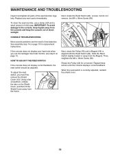
... console problems are the result of direct sunlight. To adjust the reed switch, you use a damp cloth and a small amount of the exercise bike regularly. Rotate the Pulley (43) for replacement instructions. Slide the Reed Switch slightly toward or away from the frame. To clean the exercise bike, use the handgrip heart rate monitor, see step 5 on the Shield Cover, and then lift the Shield Cover away from the Magnet. MAINTENANCE AND TROUBLESHOOTING Inspect and tighten...
... console problems are the result of direct sunlight. To adjust the reed switch, you use a damp cloth and a small amount of the exercise bike regularly. Rotate the Pulley (43) for replacement instructions. Slide the Reed Switch slightly toward or away from the frame. To clean the exercise bike, use the handgrip heart rate monitor, see step 5 on the Shield Cover, and then lift the Shield Cover away from the Magnet. MAINTENANCE AND TROUBLESHOOTING Inspect and tighten...
English Manual
Page 19
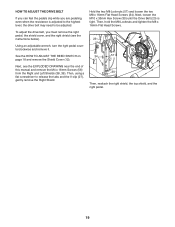
... x 16mm Flat Head Screws (34). Then, using a flat screwdriver to be adjusted. To adjust the drive belt, you are pedaling, even when the resistance is tight. See the HOW TO ADJUST THE REED SWITCH on page 18 and remove the Shield Cover (12). Next, loosen the M10 x 35mm Hex Screw (30) until the Drive Belt (23) is adjusted to the highest level, the drive belt may need to release the...
... x 16mm Flat Head Screws (34). Then, using a flat screwdriver to be adjusted. To adjust the drive belt, you are pedaling, even when the resistance is tight. See the HOW TO ADJUST THE REED SWITCH on page 18 and remove the Shield Cover (12). Next, loosen the M10 x 35mm Hex Screw (30) until the Drive Belt (23) is adjusted to the highest level, the drive belt may need to release the...
English Manual
Page 20
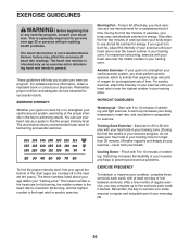
... ten years). Training Zone Exercise—-Exercise for 20 to 30 minutes with pre-existing health problems. The heart rate monitor is to make exercise a regular and enjoyable part of exercise does your physician. EXERCISE GUIDELINES WARNING: Before beginning this or any exercise program, consult your body begin to use your heart rate as you exercise—-never hold your cardiovascular system, exercising at least one day of the chart (ages...
... ten years). Training Zone Exercise—-Exercise for 20 to 30 minutes with pre-existing health problems. The heart rate monitor is to make exercise a regular and enjoyable part of exercise does your physician. EXERCISE GUIDELINES WARNING: Before beginning this or any exercise program, consult your body begin to use your heart rate as you exercise—-never hold your cardiovascular system, exercising at least one day of the chart (ages...
English Manual
Page 22
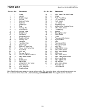
... Flat Head Screw 35 2 Wheel 36 1 Right Pedal/Strap 37 1 Left Pedal/Strap 38 1 Right Shield 39 1 Left Shield 40 2 M10 Flange Nut 41 2 M10 x 41mm Shoulder Screw 42 4 M6 x 40mm Screw 43 1 Crank/Pulley 44 2 Magnet 45 1 Bearing Assembly 46 1 Reed Switch 47 1 Clamp 48 1 Resistance Mechanism 49 1 Flywheel Axle 50 1 Idler 51 1 Resistance Motor 52 1 Resistance Cable 53 1 Main Wire 54 2 M10 x 80mm Screw 55 12 M8...
... Flat Head Screw 35 2 Wheel 36 1 Right Pedal/Strap 37 1 Left Pedal/Strap 38 1 Right Shield 39 1 Left Shield 40 2 M10 Flange Nut 41 2 M10 x 41mm Shoulder Screw 42 4 M6 x 40mm Screw 43 1 Crank/Pulley 44 2 Magnet 45 1 Bearing Assembly 46 1 Reed Switch 47 1 Clamp 48 1 Resistance Mechanism 49 1 Flywheel Axle 50 1 Idler 51 1 Resistance Motor 52 1 Resistance Cable 53 1 Main Wire 54 2 M10 x 80mm Screw 55 12 M8...

English Manual
Page 24
... WARRANTY If this Sears Bike Exerciser fails due to a defect in China © 2012 ICON IP, Inc. Sears, Roebuck and Co., Hoffman Estates, IL 60179 Part No. 328373 R0712A Printed in material or workmanship within 90 days of the date of purchase, call 1-800-4-MY-HOME® (1-800-469-4663) to state. There is used commercially or for free repair (or replacement...
... WARRANTY If this Sears Bike Exerciser fails due to a defect in China © 2012 ICON IP, Inc. Sears, Roebuck and Co., Hoffman Estates, IL 60179 Part No. 328373 R0712A Printed in material or workmanship within 90 days of the date of purchase, call 1-800-4-MY-HOME® (1-800-469-4663) to state. There is used commercially or for free repair (or replacement...


