
Owner's Manual
Page 224
... it as this may not operate normally and could be geographically limited to scratch the surface. When removing dust from the LCD screen to form inside the navigation unit, resulting in possible damage. ! Consult the connected content service provider for a long period of the LCD screen and do not press strongly...
... it as this may not operate normally and could be geographically limited to scratch the surface. When removing dust from the LCD screen to form inside the navigation unit, resulting in possible damage. ! Consult the connected content service provider for a long period of the LCD screen and do not press strongly...

Owner's Manual
Page 225
... will become dimmer and the image will improve with an increase in high temperatures. ! In that case, please consult your dealer or the nearest authorized Pioneer Service Station. Appendix Appendix En 225 At low temperatures, using the LED back- However, it may increase image lag and degrade the image quality because... lifetime of the LCD screen. Appendix LED (light-emitting diode) backlight A light emitting diode is more than 10 000 hours. light may decrease if used inside the display to illuminate the LCD screen. !
... will become dimmer and the image will improve with an increase in high temperatures. ! In that case, please consult your dealer or the nearest authorized Pioneer Service Station. Appendix Appendix En 225 At low temperatures, using the LED back- However, it may increase image lag and degrade the image quality because... lifetime of the LCD screen. Appendix LED (light-emitting diode) backlight A light emitting diode is more than 10 000 hours. light may decrease if used inside the display to illuminate the LCD screen. !

Installation Manual
Page 2
...- Parts supplied 22 - Parts supplied 26 - When using the screw holes on the dashboard or rear shelf) 25 Installing the microphone 26 - For AVIC-Z140BH users 21 Installing the navigation system 21 - Installation using a rear display connected to separately sold power amp 14 When connecting a rear view camera 16 ... video component 17 - Installation notes 21 - Using an AV input (AV2) 18 When connecting the rear display 18 - When installing the antenna inside the vehicle (on the side of the navigation unit 22 2 En - Adjusting the microphone angle 27 AVIC-Z140BH 6 -
...- Parts supplied 22 - Parts supplied 26 - When using the screw holes on the dashboard or rear shelf) 25 Installing the microphone 26 - For AVIC-Z140BH users 21 Installing the navigation system 21 - Installation using a rear display connected to separately sold power amp 14 When connecting a rear view camera 16 ... video component 17 - Installation notes 21 - Using an AV input (AV2) 18 When connecting the rear display 18 - When installing the antenna inside the vehicle (on the side of the navigation unit 22 2 En - Adjusting the microphone angle 27 AVIC-Z140BH 6 -
Installation Manual
Page 9
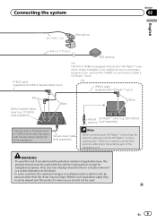
...SiriusConnect universal tuner" or "SIRIUS Dock and Play radio with SIRIUS Satellite Radio tuner) (*5) The AVIC-Z140BH is a visible distraction to the driver. · In some countries, the viewing of images on a display inside a vehicle even by persons other than the driver may be in a location where it is ...'s antenna into the HD Radio™ tuner's antenna jack. And, also rear displays should not be used . However, if you use the AVIC-X940BT, you will need to connect the vehicle's antenna to the antenna jack of the navigation unit. GEX-P20HD) antenna (sold separately) Black ...
...SiriusConnect universal tuner" or "SIRIUS Dock and Play radio with SIRIUS Satellite Radio tuner) (*5) The AVIC-Z140BH is a visible distraction to the driver. · In some countries, the viewing of images on a display inside a vehicle even by persons other than the driver may be in a location where it is ...'s antenna into the HD Radio™ tuner's antenna jack. And, also rear displays should not be used . However, if you use the AVIC-X940BT, you will need to connect the vehicle's antenna to the antenna jack of the navigation unit. GEX-P20HD) antenna (sold separately) Black ...
Installation Manual
Page 24
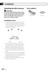
... surface where radio waves will be sure to use an extension to make it longer. Metal sheet Dashboard Rear shelf ! When installing the GPS antenna inside the vehicle, be poor. ! This would reduce the sensitivity of the GPS antenna. ! Take care not to the navigation system. Do not cut the GPS...
... surface where radio waves will be sure to use an extension to make it longer. Metal sheet Dashboard Rear shelf ! When installing the GPS antenna inside the vehicle, be poor. ! This would reduce the sensitivity of the GPS antenna. ! Take care not to the navigation system. Do not cut the GPS...

Installation Manual
Page 25
...the ability of moisture, dust, grime, oil, etc., before affixing the metal sheet. En 25 Installation Section 03 English When installing the antenna inside the vehicle. Make sure the surface is fastened with the proper functioning of such sensors or vents and may interfere with its magnet.) GPS antenna...GPS antenna on the rear. Some models use window glass that does not allow signals from GPS satellites to secure the lead where necessary inside the vehicle (on the dashboard or rear shelf) WARNING Do not install the GPS antenna over any sensors or vents on the dashboard ...
...the ability of moisture, dust, grime, oil, etc., before affixing the metal sheet. En 25 Installation Section 03 English When installing the antenna inside the vehicle. Make sure the surface is fastened with the proper functioning of such sensors or vents and may interfere with its magnet.) GPS antenna...GPS antenna on the rear. Some models use window glass that does not allow signals from GPS satellites to secure the lead where necessary inside the vehicle (on the dashboard or rear shelf) WARNING Do not install the GPS antenna over any sensors or vents on the dashboard ...
Installation Manual
Page 26
... navigation system after the system is in a place where its direction and distance from the driver make it easiest to secure the lead where necessary inside the vehicle.
... navigation system after the system is in a place where its direction and distance from the driver make it easiest to secure the lead where necessary inside the vehicle.
Installation Manual
Page 27
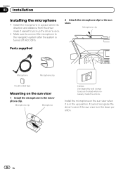
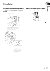
Double-sided tape Adjusting the microphone angle The microphone angle can be adjusted. En 27 Installation Section 03 English Installation on the steering column % Mount the microphone on the steering column, keeping it away from the steering wheel. Clamps Use separately sold clamps to secure the lead where necessary inside the vehicle. Install the microphone on the steering column.
Double-sided tape Adjusting the microphone angle The microphone angle can be adjusted. En 27 Installation Section 03 English Installation on the steering column % Mount the microphone on the steering column, keeping it away from the steering wheel. Clamps Use separately sold clamps to secure the lead where necessary inside the vehicle. Install the microphone on the steering column.