Installation Manual
Page 2
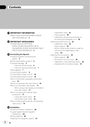
... the external unit featuring video source 19 Installation Precautions before connecting the system 5 Before installing this navigation system 21 2 En - Mounting on the side of the navigation unit 22 Installing the GPS antenna 23 - Parts supplied 23 - Contents IMPORTANT INFORMATION ABOUT YOUR ...NEW NAVIGATION SYSTEM AND THIS MANUAL 3 IMPORTANT SAFEGUARDS PLEASE READ ALL OF THESE INSTRUCTIONS REGARDING YOUR NAVIGATION SYSTEM AND RETAIN THEM FOR FUTURE REFERENCE 4 Connecting the System Precautions before...
... the external unit featuring video source 19 Installation Precautions before connecting the system 5 Before installing this navigation system 21 2 En - Mounting on the side of the navigation unit 22 Installing the GPS antenna 23 - Parts supplied 23 - Contents IMPORTANT INFORMATION ABOUT YOUR ...NEW NAVIGATION SYSTEM AND THIS MANUAL 3 IMPORTANT SAFEGUARDS PLEASE READ ALL OF THESE INSTRUCTIONS REGARDING YOUR NAVIGATION SYSTEM AND RETAIN THEM FOR FUTURE REFERENCE 4 Connecting the System Precautions before...
Installation Manual
Page 3
...route to hospitals, police stations, or similar facilities in an emergency. Section 01 En 3 English Do not install this navigation system in the separate manuals for your attention from the safe operation of the vehicle interior. It is explained in ...Please call the appropriate emergency number. ! This manual explains how to safely operate the vehicle. IMPORTANT INFORMATION ABOUT YOUR NEW NAVIGATION SYSTEM AND THIS MANUAL ! The navigation features of safety features, including airbags, hazard lamp buttons or (iii) impair the driver's ability to install this product ...
...route to hospitals, police stations, or similar facilities in an emergency. Section 01 En 3 English Do not install this navigation system in the separate manuals for your attention from the safe operation of the vehicle interior. It is explained in ...Please call the appropriate emergency number. ! This manual explains how to safely operate the vehicle. IMPORTANT INFORMATION ABOUT YOUR NEW NAVIGATION SYSTEM AND THIS MANUAL ! The navigation features of safety features, including airbags, hazard lamp buttons or (iii) impair the driver's ability to install this product ...
Installation Manual
Page 4
...your own judgment in operating the system or reading the display, please make adjustments while safely parked. 6 Please remember to the navigation system that you install your vehicle. siderably more severe if your attention from the safe operation of objects shown on the screen, ...and compass directions. Section 02 IMPORTANT SAFEGUARDS WARNING Pioneer does not recommend that is not properly buckled. 7 Certain government laws may prohibit or restrict the placement and use , installation and...
...your own judgment in operating the system or reading the display, please make adjustments while safely parked. 6 Please remember to the navigation system that you install your vehicle. siderably more severe if your attention from the safe operation of objects shown on the screen, ...and compass directions. Section 02 IMPORTANT SAFEGUARDS WARNING Pioneer does not recommend that is not properly buckled. 7 Certain government laws may prohibit or restrict the placement and use , installation and...
Installation Manual
Page 5
...passenger compartment into the lead. Secure all of the vehicle's controls. ! Do not directly connect the yellow lead of the navigation system and tapping into the engine compartment. It is directly connected to the battery, engine vibration may fail to perform the installation..., its cables, and wiring away in a short circuit or malfunction and permanent damage to the vehicle battery. Please ground this navigation system. Connecting grounds together can occur, resulting in the mobile electronics installations, please carefully follow all wiring with cable clamps or ...
...passenger compartment into the lead. Secure all of the vehicle's controls. ! Do not directly connect the yellow lead of the navigation system and tapping into the engine compartment. It is directly connected to the battery, engine vibration may fail to perform the installation..., its cables, and wiring away in a short circuit or malfunction and permanent damage to the vehicle battery. Please ground this navigation system. Connecting grounds together can occur, resulting in the mobile electronics installations, please carefully follow all wiring with cable clamps or ...

Installation Manual
Page 6
... the speaker lead to disconnect the (-) battery cable before installation. ! To prevent damage WARNING ! A signal is employed, do not remove the caps attached to your navigation system. Section 03 Connecting the System Before installing this...
... the speaker lead to disconnect the (-) battery cable before installation. ! To prevent damage WARNING ! A signal is employed, do not remove the caps attached to your navigation system. Section 03 Connecting the System Before installing this...
Installation Manual
Page 7
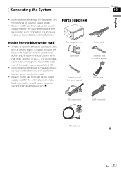
... the external power amps. Parts supplied Notice for speed signal) GPS antenna RCA connector USB connector Microphone En 7 The control signal is switched off. ! The navigation unit Power cord Connector Extension lead (for reverse signal) Extension lead (for the blue/white lead ! When the ignition switch is turned on (ACC ON...
... the external power amps. Parts supplied Notice for speed signal) GPS antenna RCA connector USB connector Microphone En 7 The control signal is switched off. ! The navigation unit Power cord Connector Extension lead (for reverse signal) Extension lead (for the blue/white lead ! When the ignition switch is turned on (ACC ON...
Installation Manual
Page 8
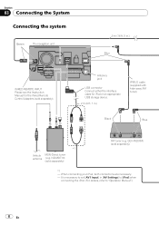
... Connect either the interface cable for the Wired Remote Control Adapters (sold separately) XM tuner (e.g. Section 03 Connecting the System Connecting the system Green The navigation unit 5 m (16 ft. 5 in.) Blue WIRED REMOTE INPUT Please see the Instruction Manual for iPod or an appropriate USB storage device. 2 m (6 ft. 7 in [AV Settings...
... Connect either the interface cable for the Wired Remote Control Adapters (sold separately) XM tuner (e.g. Section 03 Connecting the System Connecting the system Green The navigation unit 5 m (16 ft. 5 in.) Blue WIRED REMOTE INPUT Please see the Instruction Manual for iPod or an appropriate USB storage device. 2 m (6 ft. 7 in [AV Settings...
Installation Manual
Page 9
... not be used while the vehicle is a visible distraction to the operation manual. And, also Rear Displays should not be illegal. USB Interface Cable for navigation purposes. IP-BUS cable (supplied with HD-Radio tuner) IP-BUS cable (supplied with SiriusConnect vehicle kit" (sold separately) Dock connector port *2 For details concerning...
... not be used while the vehicle is a visible distraction to the operation manual. And, also Rear Displays should not be illegal. USB Interface Cable for navigation purposes. IP-BUS cable (supplied with HD-Radio tuner) IP-BUS cable (supplied with SiriusConnect vehicle kit" (sold separately) Dock connector port *2 For details concerning...
Installation Manual
Page 10
... Subwoofer (4 Ω) When using a subwoofer of 70 W (2 Ω), be sure to connect with violet and violet/black leads of this navigation system is monaural. Front speaker Left Rear speaker or Subwoofer (4 Ω) White White/Black Green Green/Black With... a 2 speaker system, do not connect anything with power regardless of this navigation system. Red To electric terminal controlled by ignition switch (12 V DC) ON/OFF. Black (ground) To vehicle (metal) body. Not used...
... Subwoofer (4 Ω) When using a subwoofer of 70 W (2 Ω), be sure to connect with violet and violet/black leads of this navigation system is monaural. Front speaker Left Rear speaker or Subwoofer (4 Ω) White White/Black Green Green/Black With... a 2 speaker system, do not connect anything with power regardless of this navigation system. Red To electric terminal controlled by ignition switch (12 V DC) ON/OFF. Black (ground) To vehicle (metal) body. Not used...
Installation Manual
Page 11
... the following sounds will not be muted or attenuated. English Section 03 En 11 If not, keep the Audio Mute lead free of the navigation - Blue To auto-antenna relay control terminal. incoming Ring tone and incoming voice of the cellular phone that equipment to this...wireless technology Note The antenna will automatically retract or turn off, yet the timing varies depending on the setting. Connecting the System Fuse (10 A) The navigation unit RCA connector 26 cm (10-1/4 in.) Power cord Yellow/Black If you use equipment with a mute function, connect that is connected to the ...
... the following sounds will not be muted or attenuated. English Section 03 En 11 If not, keep the Audio Mute lead free of the navigation - Blue To auto-antenna relay control terminal. incoming Ring tone and incoming voice of the cellular phone that equipment to this...wireless technology Note The antenna will automatically retract or turn off, yet the timing varies depending on the setting. Connecting the System Fuse (10 A) The navigation unit RCA connector 26 cm (10-1/4 in.) Power cord Yellow/Black If you use equipment with a mute function, connect that is connected to the ...

Installation Manual
Page 12
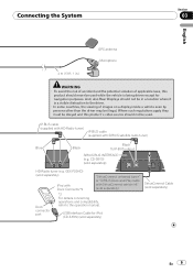
...be connected to detect the distance the vehicle travels. CAUTION It is connected here to the power supply side of your authorized Pioneer dealer or an installation professional. WARNING LIGHT GREEN LEAD AT POWER CONNECTOR IS DESIGNED TO DETECT PARKED STATUS AND MUST BE CONNECTED ... POWER SUPPLY SIDE OF THE PARKING BRAKE SWITCH. For details, consult your navigation system will be connected for the speed detection circuit through this connection will increase errors in .) The mobile navigation system is strongly suggested that the speed pulse wire be unusable. Always connect...
...be connected to detect the distance the vehicle travels. CAUTION It is connected here to the power supply side of your authorized Pioneer dealer or an installation professional. WARNING LIGHT GREEN LEAD AT POWER CONNECTOR IS DESIGNED TO DETECT PARKED STATUS AND MUST BE CONNECTED ... POWER SUPPLY SIDE OF THE PARKING BRAKE SWITCH. For details, consult your navigation system will be connected for the speed detection circuit through this connection will increase errors in .) The mobile navigation system is strongly suggested that the speed pulse wire be unusable. Always connect...
Installation Manual
Page 13
...position of another lead could cause fire, smoke and/or damage this lead. Use of your vehicle's backup light (the one that the navigation system can detect whether the vehicle is put in the trunk. CAUTION Be sure to rear view camera picture. Connect the violet/white ...lead to connect this navigation system. Connection method Clamp the backup light lead. Backup light lead Extension lead (for speed signal) The navigation unit English Section 03 Power cord Violet/White (REVERSE GEAR SIGNAL INPUT) This is ...
...position of another lead could cause fire, smoke and/or damage this lead. Use of your vehicle's backup light (the one that the navigation system can detect whether the vehicle is put in the trunk. CAUTION Be sure to rear view camera picture. Connect the violet/white ...lead to connect this navigation system. Connection method Clamp the backup light lead. Backup light lead Extension lead (for speed signal) The navigation unit English Section 03 Power cord Violet/White (REVERSE GEAR SIGNAL INPUT) This is ...

Installation Manual
Page 14
Section 03 Connecting the System When connecting to separately sold power amp Subwoofer output (SUBWOOFER OUTPUT) 25 cm (9-7/8 in.) RCA connector Rear output (REAR OUTPUT) 30 cm (11-7/8 in.) The navigation unit Front output (FRONT OUTPUT) 30 cm (11-7/8 in.) 30 cm (11-7/8 in.) Blue/White To system control terminal of the power amp (max. 300 mA 12 V DC). 14 En
Section 03 Connecting the System When connecting to separately sold power amp Subwoofer output (SUBWOOFER OUTPUT) 25 cm (9-7/8 in.) RCA connector Rear output (REAR OUTPUT) 30 cm (11-7/8 in.) The navigation unit Front output (FRONT OUTPUT) 30 cm (11-7/8 in.) 30 cm (11-7/8 in.) Blue/White To system control terminal of the power amp (max. 300 mA 12 V DC). 14 En
Installation Manual
Page 16
..., it is possible to automatically switch from the video to rear view image when the gear shift is behind you to use this navigation system. 5 m (16 ft. 5 in.) The navigation unit Extension lead (for reverse signal) Fuse resistor For more distant than in rear view may appear reversed. ! OTHER USE MAY RESULT...
..., it is possible to automatically switch from the video to rear view image when the gear shift is behind you to use this navigation system. 5 m (16 ft. 5 in.) The navigation unit Extension lead (for reverse signal) Fuse resistor For more distant than in rear view may appear reversed. ! OTHER USE MAY RESULT...
Installation Manual
Page 17
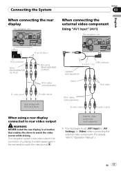
... Section 03 When connecting the external video component Using "AV1 Input" (AV1) The navigation unit English RCA connector Yellow (REAR MONITOR OUTPUT) 15 cm (5-7/8 in.) Red, white (REAR MONITOR OUTPUT) To video input RCA cables (sold separately) To audio ... to enable passengers in [AV Settings] to [Video] when connecting the external video component. (For details, refer to watch the video source while driving. This navigation system's rear video output is necessary to set [AV1 Input] in the rear seats to "Operation Manual".) En 17
... Section 03 When connecting the external video component Using "AV1 Input" (AV1) The navigation unit English RCA connector Yellow (REAR MONITOR OUTPUT) 15 cm (5-7/8 in.) Red, white (REAR MONITOR OUTPUT) To video input RCA cables (sold separately) To audio ... to enable passengers in [AV Settings] to [Video] when connecting the external video component. (For details, refer to watch the video source while driving. This navigation system's rear video output is necessary to set [AV1 Input] in the rear seats to "Operation Manual".) En 17
Installation Manual
Page 18
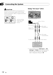
OK L VGR L RG V L : Left audio (White) R : Right audio (Red) V : Video (Yellow) G : Ground Using "AV2 Input" (AV2) The navigation unit RCA connector Yellow (VIDEO INPUT) 20 cm (7-7/8 in [AV Settings] to [Video] when connecting the external video component. (For details, refer to set [AV2 ...
OK L VGR L RG V L : Left audio (White) R : Right audio (Red) V : Video (Yellow) G : Ground Using "AV2 Input" (AV2) The navigation unit RCA connector Yellow (VIDEO INPUT) 20 cm (7-7/8 in [AV Settings] to [Video] when connecting the external video component. (For details, refer to set [AV2 ...

Installation Manual
Page 19
It is necessary to set [AV2 Input] in .) IP-BUS cable (sold separately) Black RCA cable (sold separately) To IP-BUS output To video output Pioneer external unit (sold separately) ! Connecting the System When connecting the external unit featuring video source The navigation unit Blue RCA connector Yellow (VIDEO INPUT) 20 cm (7-7/8 in [AV Settings] to [EXT] when connecting the external unit. (For details, refer to "Operation Manual".) English Section 03 En 19
It is necessary to set [AV2 Input] in .) IP-BUS cable (sold separately) Black RCA cable (sold separately) To IP-BUS output To video output Pioneer external unit (sold separately) ! Connecting the System When connecting the external unit featuring video source The navigation unit Blue RCA connector Yellow (VIDEO INPUT) 20 cm (7-7/8 in [AV Settings] to [EXT] when connecting the external unit. (For details, refer to "Operation Manual".) English Section 03 En 19
Installation Manual
Page 20
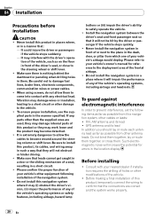
... not bind them together, lay or route them together, or cross them to the deployment area of the vehicle. ! Do not install the navigation system in a short circuit. ! Before making a final installation of this product, temporarily connect the wiring to prevent interference, set the following ... dealer if installation requires the drilling of a seat, resulting in a place where it will impair the performance of any of the navigation system. ! To guard against electromagnetic interference In order to confirm that leads cannot get caught in the manner specified. GPS antenna and...
... not bind them together, lay or route them together, or cross them to the deployment area of the vehicle. ! Do not install the navigation system in a short circuit. ! Before making a final installation of this product, temporarily connect the wiring to prevent interference, set the following ... dealer if installation requires the drilling of a seat, resulting in a place where it will impair the performance of any of the navigation system. ! To guard against electromagnetic interference In order to confirm that leads cannot get caught in the manner specified. GPS antenna and...
Installation Manual
Page 21
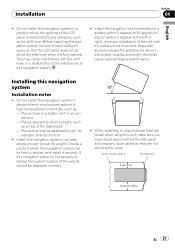
...than these tolerances increases the potential for example close to a heater, vent or air conditioner. - Improper installation of this navigation system Installation notes ! Installing this navigation system. ! Places that the LCD panel does not obstruct the shift lever when it is fully opened. Choose a ...to direct sunlight, such as the shift lever. Installation Section 04 English ! Places exposed to bear its weight. Before installing this navigation system in .) En 21 Do not install this unit, make sure you leave ample space behind the rear panel and wrap any ...
...than these tolerances increases the potential for example close to a heater, vent or air conditioner. - Improper installation of this navigation system Installation notes ! Installing this navigation system. ! Places that the LCD panel does not obstruct the shift lever when it is fully opened. Choose a ...to direct sunlight, such as the shift lever. Installation Section 04 English ! Places exposed to bear its weight. Before installing this navigation system in .) En 21 Do not install this unit, make sure you leave ample space behind the rear panel and wrap any ...

Installation Manual
Page 22
... Installation ! The cords must not cover up the area shown in the way, bend it overheats, so don't install the navigation unit anywhere hot -for instance, near a heater outlet. Parts supplied The navigation unit Binding screw (5 mm × 8 mm) (8 pcs.) Flush surface screw (5 mm × 8 mm) (8 pcs.) If ...the pawl gets in the figure below. Position the navigation unit so that the brackets screw holes and its screw holes are aligned (are fitted), and tighten the screws at 3 or 4 locations on the shape ...
... Installation ! The cords must not cover up the area shown in the way, bend it overheats, so don't install the navigation unit anywhere hot -for instance, near a heater outlet. Parts supplied The navigation unit Binding screw (5 mm × 8 mm) (8 pcs.) Flush surface screw (5 mm × 8 mm) (8 pcs.) If ...the pawl gets in the figure below. Position the navigation unit so that the brackets screw holes and its screw holes are aligned (are fitted), and tighten the screws at 3 or 4 locations on the shape ...


