Installation Manual
Page 2
... supplied 26 - Contents IMPORTANT INFORMATION ABOUT YOUR NEW NAVIGATION SYSTEM AND THIS MANUAL 3 IMPORTANT SAFEGUARDS PLEASE READ ALL OF THESE INSTRUCTIONS REGARDING YOUR NAVIGATION SYSTEM AND RETAIN THEM FOR FUTURE REFERENCE 4 Connecting the System Precautions before installation 20 To guard against electromagnetic interference 20...24 - Parts supplied 22 - Installation notes 21 - Adjusting the microphone angle 27 After Installation After Installing this Navigation System 28 Installation using a rear display connected to separately sold power amp 14 When connecting a rear view camera 16 ...
... supplied 26 - Contents IMPORTANT INFORMATION ABOUT YOUR NEW NAVIGATION SYSTEM AND THIS MANUAL 3 IMPORTANT SAFEGUARDS PLEASE READ ALL OF THESE INSTRUCTIONS REGARDING YOUR NAVIGATION SYSTEM AND RETAIN THEM FOR FUTURE REFERENCE 4 Connecting the System Precautions before installation 20 To guard against electromagnetic interference 20...24 - Parts supplied 22 - Installation notes 21 - Adjusting the microphone angle 27 After Installation After Installing this Navigation System 28 Installation using a rear display connected to separately sold power amp 14 When connecting a rear view camera 16 ...
Installation Manual
Page 3
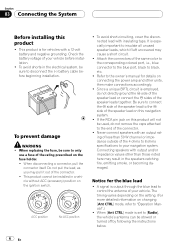
... or (iii) impair the driver's ability to aid you in the separate manuals for your vehicle. This manual explains how to install this navigation system is not a substitute for the navigation system. ! In some cases, it may not be possible to install this navigation system (or the rear view camera option if purchased) if doing so in your...
... or (iii) impair the driver's ability to aid you in the separate manuals for your vehicle. This manual explains how to install this navigation system is not a substitute for the navigation system. ! In some cases, it may not be possible to install this navigation system (or the rear view camera option if purchased) if doing so in your...
Installation Manual
Page 4
... your seat belt at all warnings in this manual and follow the instructions carefully. 4 This navigation system may in your vehicle. Please comply with any accessory in electronic equipment and 4 En In addition, the system has certain limitations, including the inability to identify... Section 02 IMPORTANT SAFEGUARDS PLEASE READ ALL OF THESE INSTRUCTIONS REGARDING YOUR NAVIGATION SYSTEM AND RETAIN THEM FOR FUTURE REFERENCE 1 Read this manual fully and carefully before installing your navigation system. 2 Keep this manual handy for future reference. 3 Pay close attention to all times while...
... your seat belt at all warnings in this manual and follow the instructions carefully. 4 This navigation system may in your vehicle. Please comply with any accessory in electronic equipment and 4 En In addition, the system has certain limitations, including the inability to identify... Section 02 IMPORTANT SAFEGUARDS PLEASE READ ALL OF THESE INSTRUCTIONS REGARDING YOUR NAVIGATION SYSTEM AND RETAIN THEM FOR FUTURE REFERENCE 1 Read this manual fully and carefully before installing your navigation system. 2 Keep this manual handy for future reference. 3 Pay close attention to all times while...
Installation Manual
Page 5
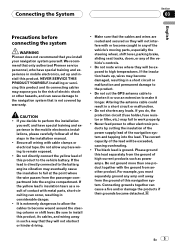
...allow any of high-current products such as a result of the navigation system and tapping into the engine compartment. If the insulation heats up and install this product and its cables, and wiring away in the installation manual. ! The black lead is extremely dangerous to the vehicle battery..., and can cause a fire and/or damage the products if their grounds became detached. Connecting the System Section 03 English Precautions before connecting the system WARNING Pioneer does not recommend that is not covered by cutting the insulation of the power supply lead of contact ...
...allow any of high-current products such as a result of the navigation system and tapping into the engine compartment. If the insulation heats up and install this product and its cables, and wiring away in the installation manual. ! The black lead is extremely dangerous to the vehicle battery..., and can cause a fire and/or damage the products if their grounds became detached. Connecting the System Section 03 English Precautions before connecting the system WARNING Pioneer does not recommend that is not covered by cutting the insulation of the power supply lead of contact ...
Installation Manual
Page 6
...CTRL] mode, refer to control the antenna of the connector. ! It is output through the blue lead to "Operation Manual".) ! Notice for details on this navigation system. ! To avoid short-circuiting, cover the disconnected lead with an output rating of less than those noted here may pull... it out of your navigation system. When disconnecting a connector, pull the connector itself. The timing varies depending on the setting. (For more detailed information on this...
...CTRL] mode, refer to control the antenna of the connector. ! It is output through the blue lead to "Operation Manual".) ! Notice for details on this navigation system. ! To avoid short-circuiting, cover the disconnected lead with an output rating of less than those noted here may pull... it out of your navigation system. When disconnecting a connector, pull the connector itself. The timing varies depending on the setting. (For more detailed information on this...
Installation Manual
Page 8
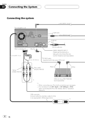
Section 03 Connecting the System Connecting the system The navigation unit 4 m (13 ft. 1 in.) Light gray 5 m (16 ft. 5 in.) RCA connector 2 m (6 ft. 7 in.) Blue 20 cm (7-7/8 in [AV Settings] to [iPod] when connecting the iPod. (For details, refer to "Operation Manual".) USB connector Connect either the interface cable for the Wired... XM tuner (e.g. It is necessary to set [AV1 Input] in .) Antenna jack Vehicle antenna WIRED REMOTE INPUT Please see the Instruction Manual for iPod or an appropriate USB storage device. *1 8 En When connecting your iPod, both connections are necessary. -
Section 03 Connecting the System Connecting the system The navigation unit 4 m (13 ft. 1 in.) Light gray 5 m (16 ft. 5 in.) RCA connector 2 m (6 ft. 7 in.) Blue 20 cm (7-7/8 in [AV Settings] to [iPod] when connecting the iPod. (For details, refer to "Operation Manual".) USB connector Connect either the interface cable for the Wired... XM tuner (e.g. It is necessary to set [AV1 Input] in .) Antenna jack Vehicle antenna WIRED REMOTE INPUT Please see the Instruction Manual for iPod or an appropriate USB storage device. *1 8 En When connecting your iPod, both connections are necessary. -
Installation Manual
Page 9
Connecting the System Section 03 English Microphone GPS antenna DIGITAL OUT This terminal is a visible distraction to the driver. · In some countries or states, the viewing of ... with SiriusConnect vehicle kit" (sold separately) SiriusConnect Cable (sold separately) Dock connector port USB Interface Cable for navigation purposes. En 9 Also Rear Displays should not be in a location where it is intended to "Operation Manual". Note The XM tuner, HD-Radio tuner and SIRIUS satellite radio tuner will not receive their coverage...
Connecting the System Section 03 English Microphone GPS antenna DIGITAL OUT This terminal is a visible distraction to the driver. · In some countries or states, the viewing of ... with SiriusConnect vehicle kit" (sold separately) SiriusConnect Cable (sold separately) Dock connector port USB Interface Cable for navigation purposes. En 9 Also Rear Displays should not be in a location where it is intended to "Operation Manual". Note The XM tuner, HD-Radio tuner and SIRIUS satellite radio tuner will not receive their coverage...

Installation Manual
Page 10
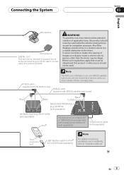
...ignition switch position. Do not connect anything to the speaker leads that are not connected to "Operation Manual".) The subwoofer output of this navigation system is connected to this navigation system. Not used. Red To electric terminal controlled by ignition switch (12 V DC) ON/OFF. ...Black (ground) To vehicle (metal) body. Section 03 Connecting the System Connecting the power cord (1) Yellow To terminal...
...ignition switch position. Do not connect anything to the speaker leads that are not connected to "Operation Manual".) The subwoofer output of this navigation system is connected to this navigation system. Not used. Red To electric terminal controlled by ignition switch (12 V DC) ON/OFF. ...Black (ground) To vehicle (metal) body. Section 03 Connecting the System Connecting the power cord (1) Yellow To terminal...
Installation Manual
Page 11
... RCA connector 26 cm (10-1/4 in.) Power cord Yellow/Black If you use equipment with a mute function, connect that is connected to this navigation system via Bluetooth wireless technology Note The antenna will automatically retract or turn off, yet the timing varies depending on the setting. voice guidance of any ..., connect to mute or attenuate, while the following sounds will not be muted or attenuated. If not, keep the Audio Mute lead free of the navigation - For details, see "Operation Manual". - Blue To auto-antenna relay control terminal.
... RCA connector 26 cm (10-1/4 in.) Power cord Yellow/Black If you use equipment with a mute function, connect that is connected to this navigation system via Bluetooth wireless technology Note The antenna will automatically retract or turn off, yet the timing varies depending on the setting. voice guidance of any ..., connect to mute or attenuate, while the following sounds will not be muted or attenuated. If not, keep the Audio Mute lead free of the navigation - For details, see "Operation Manual". - Blue To auto-antenna relay control terminal.
Installation Manual
Page 14
Section 03 Connecting the System When connecting to separately sold power amp Subwoofer output (SUBWOOFER OUTPUT) 28cm (11 in.) RCA connector Rear output (REAR OUTPUT) 30cm (11-7/8 in.) The navigation unit Front output (FRONT OUTPUT) 30cm (11-7/8 in.) 30cm (11-7/8 in.) Blue/white To system control terminal of the power amp (max. 300 mA 12 V DC). 14 En Note You can change the RCA output of the subwoofer depending on your subwoofer system. (Refer to "Operation Manual".)
Section 03 Connecting the System When connecting to separately sold power amp Subwoofer output (SUBWOOFER OUTPUT) 28cm (11 in.) RCA connector Rear output (REAR OUTPUT) 30cm (11-7/8 in.) The navigation unit Front output (FRONT OUTPUT) 30cm (11-7/8 in.) 30cm (11-7/8 in.) Blue/white To system control terminal of the power amp (max. 300 mA 12 V DC). 14 En Note You can change the RCA output of the subwoofer depending on your subwoofer system. (Refer to "Operation Manual".)

Installation Manual
Page 16
...into a tight parking spot. Please note that the edges of another lead could cause fire, smoke and/or damage this navigation system. 5 m (16 ft. 5 in .) Power cord CAUTION ! It is necessary to set [Back Camera] in ...video output RCA cable Violet/white Brown (REAR VIEW CAMERA IN) 20 cm RCA connector (7-7/8 in .) The navigation unit Extension lead (for checking the rear when the vehicle is moved to REVERSE (R). Use of the rear...the gear shift is moving forward. Section 03 Connecting the System When connecting a rear view camera When this product is used for reverse signal) Fuse resistor ...
...into a tight parking spot. Please note that the edges of another lead could cause fire, smoke and/or damage this navigation system. 5 m (16 ft. 5 in .) Power cord CAUTION ! It is necessary to set [Back Camera] in ...video output RCA cable Violet/white Brown (REAR VIEW CAMERA IN) 20 cm RCA connector (7-7/8 in .) The navigation unit Extension lead (for checking the rear when the vehicle is moved to REVERSE (R). Use of the rear...the gear shift is moving forward. Section 03 Connecting the System When connecting a rear view camera When this product is used for reverse signal) Fuse resistor ...
Installation Manual
Page 17
... When connecting the external video component Using "AV1 Input" (AV1) The navigation unit 15 cm (5-7/8 in.) RCA connector Yellow (REAR MONITOR OUTPUT) RCA cables (sold separately) To video input RCA connector Yellow (VIDEO INPUT) Rear display ...that enables the driver to "Operation Manual".) En 17 It is necessary to set [AV1 Input] in the rear seats to watch the video source while driving. Connecting the System Section 03 English When connecting the rear display This connection is for AVICF700BT and AVIC-F7010BT. This navigation system's rear video output is unnecessary for...
... When connecting the external video component Using "AV1 Input" (AV1) The navigation unit 15 cm (5-7/8 in.) RCA connector Yellow (REAR MONITOR OUTPUT) RCA cables (sold separately) To video input RCA connector Yellow (VIDEO INPUT) Rear display ...that enables the driver to "Operation Manual".) En 17 It is necessary to set [AV1 Input] in the rear seats to watch the video source while driving. Connecting the System Section 03 English When connecting the rear display This connection is for AVICF700BT and AVIC-F7010BT. This navigation system's rear video output is unnecessary for...
Installation Manual
Page 18
... L RG V L : Left audio (White) R : Right audio (Red) V : Video (Yellow) G : Ground To video output To audio outputs External video component (sold separately) ! Section 03 Connecting the System Using "AV2 Input" (AV2) The navigation unit Mini jack CD-RM10 (sold separately) Yellow RCA cables (sold separately) Red, white CAUTION Be sure to "Operation...
... L RG V L : Left audio (White) R : Right audio (Red) V : Video (Yellow) G : Ground To video output To audio outputs External video component (sold separately) ! Section 03 Connecting the System Using "AV2 Input" (AV2) The navigation unit Mini jack CD-RM10 (sold separately) Yellow RCA cables (sold separately) Red, white CAUTION Be sure to "Operation...
Installation Manual
Page 19
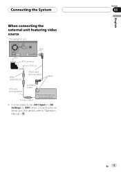
Connecting the System When connecting the external unit featuring video source The navigation unit Blue RCA connector 20 cm (7-7/8 in [AV Settings] to [EXT] when connecting the external unit. (For details, refer to "Operation Manual".) English Section 03 En 19 It is necessary to set [AV1 Input] in .) Yellow (VIDEO INPUT) IP-BUS cable (sold separately) Black RCA cable (sold separately) To IP-BUS output To video output Pioneer external unit (sold separately) !
Connecting the System When connecting the external unit featuring video source The navigation unit Blue RCA connector 20 cm (7-7/8 in [AV Settings] to [EXT] when connecting the external unit. (For details, refer to "Operation Manual".) English Section 03 En 19 It is necessary to set [AV1 Input] in .) Yellow (VIDEO INPUT) IP-BUS cable (sold separately) Black RCA cable (sold separately) To IP-BUS output To video output Pioneer external unit (sold separately) !
Installation Manual
Page 20
...features, including airbags, hazard lamp buttons or (iii) impair the driver's ability to authorized Pioneer service personnel. Do not install the navigation system in a door or the sliding mechanism of this navigation system where it will not be hit by the driver or passenger if the vehicle stops quickly...deploy. Never install the navigation system in front of or next to the place in the manner specified. It could injure the driver or passengers if the vehicle stops suddenly. - Vibration may expose you install or service your vehicle's owner's manual for reference to the ...
...features, including airbags, hazard lamp buttons or (iii) impair the driver's ability to authorized Pioneer service personnel. Do not install the navigation system in a door or the sliding mechanism of this navigation system where it will not be hit by the driver or passenger if the vehicle stops quickly...deploy. Never install the navigation system in front of or next to the place in the manner specified. It could injure the driver or passengers if the vehicle stops suddenly. - Vibration may expose you install or service your vehicle's owner's manual for reference to the ...

Installation Manual
Page 28
Section 05 After Installation After Installing this navigation system, be sure to "Operation Manual". 1 Set the language. 2 Drive an unobstructed road until the GPS starts receiving the signal normally. 3 Make some necessary adjustments. ! Then reconnect the negative... that all vehicle components that this product is performing normally. 28 En Reassemble all connections are correct and that you prefer Note After installing this Navigation System 1 Reconnecting the battery. Setting the time ! Change other settings as the tip of the battery. 2 Start the engine. 3 Press RESET button....
Section 05 After Installation After Installing this navigation system, be sure to "Operation Manual". 1 Set the language. 2 Drive an unobstructed road until the GPS starts receiving the signal normally. 3 Make some necessary adjustments. ! Then reconnect the negative... that all vehicle components that this product is performing normally. 28 En Reassemble all connections are correct and that you prefer Note After installing this Navigation System 1 Reconnecting the battery. Setting the time ! Change other settings as the tip of the battery. 2 Start the engine. 3 Press RESET button....
Owner's Manual
Page 1
... must understand before using this navigation system. Operation Manual FLASH MEMORY MULTIMEDIA AV NAVIGATION RECEIVER AVIC-F900BT AVIC-F700BT AVIC-F7010BT Notice to all users: Be sure to read "Important Information for the user" includes the important information that the navigation system is properly connected to your vehicle's parking brake and depending on your Authorized Pioneer Electronics retailer or call us...
... must understand before using this navigation system. Operation Manual FLASH MEMORY MULTIMEDIA AV NAVIGATION RECEIVER AVIC-F900BT AVIC-F700BT AVIC-F7010BT Notice to all users: Be sure to read "Important Information for the user" includes the important information that the navigation system is properly connected to your vehicle's parking brake and depending on your Authorized Pioneer Electronics retailer or call us...
Owner's Manual
Page 2
The actual screens may differ from startup to termination 16 On first-time startup 16 2 En Regular startup 17 How to use the navigation menu screens 18 - About the definition of the map 22 - Inserting an SD memory card 15 - Switching the map between 2D and ... a location by recalling a saved route 34 How to see 22 - After you want to read the map screen 20 - Introduction Manual overview 8 - Scrolling the map to read this Pioneer product. Disconnecting your home 34 Setting a route by coordinates 32 Selecting a location you searched for a nearby POI 28 - Ejecting a...
The actual screens may differ from startup to termination 16 On first-time startup 16 2 En Regular startup 17 How to use the navigation menu screens 18 - About the definition of the map 22 - Inserting an SD memory card 15 - Switching the map between 2D and ... a location by recalling a saved route 34 How to see 22 - After you want to read the map screen 20 - Introduction Manual overview 8 - Scrolling the map to read this Pioneer product. Disconnecting your home 34 Setting a route by coordinates 32 Selecting a location you searched for a nearby POI 28 - Ejecting a...
Owner's Manual
Page 8
...body of this : e.g.) = For details, refer to Setting your navigation system depends the settings for use of terminology "Front Display" and "Rear Display" In this manual, the screen that you use your new navigation system. Chapter 8 describes the operations related to read the following format: e.g.)...built-in audio and visual source or operate the audio equipment connected to suit your navigation system are described in ALL CAPITAL, BOLD lettering: e.g.) MENU button, MAP button. ! This manual provides important information you need from a menu name If you greatly as the "...
...body of this : e.g.) = For details, refer to Setting your navigation system depends the settings for use of terminology "Front Display" and "Rear Display" In this manual, the screen that you use your new navigation system. Chapter 8 describes the operations related to read the following format: e.g.)...built-in audio and visual source or operate the audio equipment connected to suit your navigation system are described in ALL CAPITAL, BOLD lettering: e.g.) MENU button, MAP button. ! This manual provides important information you need from a menu name If you greatly as the "...

Owner's Manual
Page 9
... (AVIC-F900BTand AVIC-F90BT) DVD-Video (commercial-release DVDVideo), DVD-R/-RW/-R DL (DVD-Video, DVD-VR, Data), CD (commercial-release audio CD), CD-R/RW (CD-DA, Data) En 9 p Imported original images will re-calculate the route from that point so that is connected to this navigation system. ... SD)". Introduction Chapter 01 Introduction "Video image" "Video image" in this manual indicates the moving images of DVD-Video, DivX, iPod, and any equipment that you deviate from the set route, the system will be set up as customized splash screens. You can store your original image...
... (AVIC-F900BTand AVIC-F90BT) DVD-Video (commercial-release DVDVideo), DVD-R/-RW/-R DL (DVD-Video, DVD-VR, Data), CD (commercial-release audio CD), CD-R/RW (CD-DA, Data) En 9 p Imported original images will re-calculate the route from that point so that is connected to this navigation system. ... SD)". Introduction Chapter 01 Introduction "Video image" "Video image" in this manual indicates the moving images of DVD-Video, DivX, iPod, and any equipment that you deviate from the set route, the system will be set up as customized splash screens. You can store your original image...


