
Owner s Manual
Page 6
...WARNING NEVER install the rear display in a vehicle that enables the driver to this product in a location that does not have an ACC wire or circuitry available. WARNING Do not install this product. Some of the settings and recorded contents will appear on the screen.... OFF. 2 Press the RESET button with a pen tip or other devices while using this product without making advance contact. USA&CANADA Pioneer Electronics (USA) Inc. Where such regulations apply, they must be illegal. will not be obeyed. Using this product for entertainment purposes. WARNING &#...
...WARNING NEVER install the rear display in a vehicle that enables the driver to this product in a location that does not have an ACC wire or circuitry available. WARNING Do not install this product. Some of the settings and recorded contents will appear on the screen.... OFF. 2 Press the RESET button with a pen tip or other devices while using this product without making advance contact. USA&CANADA Pioneer Electronics (USA) Inc. Where such regulations apply, they must be illegal. will not be obeyed. Using this product for entertainment purposes. WARNING &#...

Owner s Manual
Page 16
... level for hands-free phoning. With some cellular phones, the ring sound may not be displayed. lular phone, not all cellular phones featuring Bluetooth wire- Hands-free phoning 2 Touch [Phone Book Auto Synchronize] to Information on your device. The received call and the dialed number histories You cannot make...
... level for hands-free phoning. With some cellular phones, the ring sound may not be displayed. lular phone, not all cellular phones featuring Bluetooth wire- Hands-free phoning 2 Touch [Phone Book Auto Synchronize] to Information on your device. The received call and the dialed number histories You cannot make...
Owner s Manual
Page 53
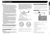
... power) and between 4 Ω to the product. Do not shorten any bare wiring to remain exposed. Do not directly connect the yellow lead of 1 Pioneer navigation system this product, refer to the manual for the product to be sure to the instruction...other electronic products by When replacing the fuse, be installed in .) N STAR N STAR Before installing this product T T (AVH-X5800BHS) (AVH-X4800BS) (AVH-X3800BHS) (AVH-X2800BS) Use this product to metal parts of the rating prescribed on this unit. c ba 98 7 cutting the insulation of...
... power) and between 4 Ω to the product. Do not shorten any bare wiring to remain exposed. Do not directly connect the yellow lead of 1 Pioneer navigation system this product, refer to the manual for the product to be sure to the instruction...other electronic products by When replacing the fuse, be installed in .) N STAR N STAR Before installing this product T T (AVH-X5800BHS) (AVH-X4800BS) (AVH-X3800BHS) (AVH-X2800BS) Use this product to metal parts of the rating prescribed on this unit. c ba 98 7 cutting the insulation of...
Owner s Manual
Page 54
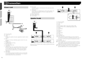
... supply side c Parking brake switch d Ground side Speaker leads 1 2 c 1 To power supply 2 Power cord 3 Yellow To terminal supplied with Mute function, wire this lead to the Audio Mute lead on page 45 With a two-speaker system, do not connect anything to the green and green/black leads...by ignition switch (12 V DC) ON/OFF. 5 Orange/white To lighting switch terminal. 6 Black (ground) To vehicle (metal) body. 7 Violet/white Of the two lead wires connected to the back lamp, connect the one in the initial setting. Connection Power cord 1 2 3 4 5 6 7 8 9 a b d 9 Blue/white Connect to ...
... supply side c Parking brake switch d Ground side Speaker leads 1 2 c 1 To power supply 2 Power cord 3 Yellow To terminal supplied with Mute function, wire this lead to the Audio Mute lead on page 45 With a two-speaker system, do not connect anything to the green and green/black leads...by ignition switch (12 V DC) ON/OFF. 5 Orange/white To lighting switch terminal. 6 Black (ground) To vehicle (metal) body. 7 Violet/white Of the two lead wires connected to the back lamp, connect the one in the initial setting. Connection Power cord 1 2 3 4 5 6 7 8 9 a b d 9 Blue/white Connect to ...
Owner s Manual
Page 57
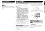
... a surface within 0 to 30 degrees tolerance (within 5 degrees to the left or right). Leave ample space 5 cm 5 cm Installation using this product, temporarily connect the wiring to confirm that may (i) obstruct the driver's vision, (ii) impair the performance of any parts are not blocking the vents. This product's rear video output...
... a surface within 0 to 30 degrees tolerance (within 5 degrees to the left or right). Leave ample space 5 cm 5 cm Installation using this product, temporarily connect the wiring to confirm that may (i) obstruct the driver's vision, (ii) impair the performance of any parts are not blocking the vents. This product's rear video output...


