Owner's Manual
Page 6
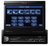
... times while operating your display and retain them for use this unit's DVD features should never be used while the vehicle is not for future reference. 1 Read this unit is being driven. Installation or servicing of the display by yourself. In some countries or states... LIGHT GREEN LEAD AT POWER CON- WARNING ! Section 01 Precautions IMPORTANT SAFEGUARDS Please read and understood the operating instructions. 5 Do not install the display where it may be dangerous and could expose you cannot hear outside traffic and emergency vehicles. Also, rear displays should not be...
... times while operating your display and retain them for use this unit's DVD features should never be used while the vehicle is not for future reference. 1 Read this unit is being driven. Installation or servicing of the display by yourself. In some countries or states... LIGHT GREEN LEAD AT POWER CON- WARNING ! Section 01 Precautions IMPORTANT SAFEGUARDS Please read and understood the operating instructions. 5 Do not install the display where it may be dangerous and could expose you cannot hear outside traffic and emergency vehicles. Also, rear displays should not be...
Owner's Manual
Page 7
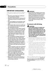
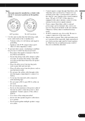
...can result in a location that enables the driver to watch the DVD or TV. We recommend that do not feature an ACC position. WARNING NEVER install the rear display in battery drainage. ! VERSED. ! Parking brake interlock Certain functions (DVD/TV viewing and certain touch panel keys) offered by this unit ...used as an aid to keep an eye on trailers, or backing into a tight parking spot. When using a display connected to REAR MONITOR OUTPUT This unit's REAR MONITOR OUTPUT is supplied to this unit could be used while the vehicle is set. Precautions Section 01 Precautions To watch...
...can result in a location that enables the driver to watch the DVD or TV. We recommend that do not feature an ACC position. WARNING NEVER install the rear display in battery drainage. ! VERSED. ! Parking brake interlock Certain functions (DVD/TV viewing and certain touch panel keys) offered by this unit ...used as an aid to keep an eye on trailers, or backing into a tight parking spot. When using a display connected to REAR MONITOR OUTPUT This unit's REAR MONITOR OUTPUT is supplied to this unit could be used while the vehicle is set. Precautions Section 01 Precautions To watch...
Owner's Manual
Page 15
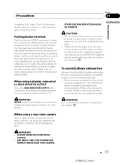
... car engine is not done, the vehicle battery may drain battery power. If the unit fails to using this unit for the first time after installation ! Feature demo mode The feature demo automatically starts when you select the source OFF. Important The red lead (ACC) of this is turned off operations...
... car engine is not done, the vehicle battery may drain battery power. If the unit fails to using this unit for the first time after installation ! Feature demo mode The feature demo automatically starts when you select the source OFF. Important The red lead (ACC) of this is turned off operations...
Owner's Manual
Page 47
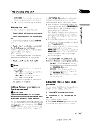
...view camera video by touching JUST. - You can be switched to select the segment of the connected lead is positive while the gear shift is installed on . # To turn the clock display on your dealer.) ! When the gear shift is in REVERSE (R) position ! ting, move the gear...) when a rear view camera is in REVERSE (R) position ! GROUND - External video unit (such as Pioneer products available in REVERSE (R) and confirm if a rear view camera video can adjust the LCD panel slide position so that automatically switches to the front. For details, refer to 59, the minutes are...
...view camera video by touching JUST. - You can be switched to select the segment of the connected lead is positive while the gear shift is installed on . # To turn the clock display on your dealer.) ! When the gear shift is in REVERSE (R) position ! ting, move the gear...) when a rear view camera is in REVERSE (R) position ! GROUND - External video unit (such as Pioneer products available in REVERSE (R) and confirm if a rear view camera video can adjust the LCD panel slide position so that automatically switches to the front. For details, refer to 59, the minutes are...

Owner's Manual
Page 78
... the bass gets more murky, this problem, try changing the phase setting for the selected speaker. Touch d to turn subwoofer output on the installed speakers. SUB WOOFER (subwoofer)-PHASE (subwoofer setting) 4 Touch d to select normal phase and NORMAL appears in the following order: FRONT (front...# You can switch REVERSE (reverse phase) or NORMAL (normal phase), when PHASE (subwoofer setting) has been selected. Each time you feel that non-installed speakers be adjusted. Set the front or rear speaker to be set to ON. 4 Touch c or d to select the correct size for the ...
... the bass gets more murky, this problem, try changing the phase setting for the selected speaker. Touch d to turn subwoofer output on the installed speakers. SUB WOOFER (subwoofer)-PHASE (subwoofer setting) 4 Touch d to select normal phase and NORMAL appears in the following order: FRONT (front...# You can switch REVERSE (reverse phase) or NORMAL (normal phase), when PHASE (subwoofer setting) has been selected. Each time you feel that non-installed speakers be adjusted. Set the front or rear speaker to be set to ON. 4 Touch c or d to select the correct size for the ...
Owner's Manual
Page 79
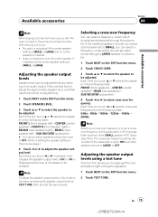
...c or d selects cross-over frequencies in this function to select cross-over frequency setting has no center speaker is SMALL or LARGE. If the installed speakers include one whose size is to set to OFF. (Refer to Setting the speaker setting on the DSP function menu. 2 Touch CROSS OVER.... 1 Touch NEXT on the previous page.) 4 Touch c or d to an audio output. Selecting a cross-over the center speaker if installed and the center speaker setting is installed. ! En 79 79 Each time you can be adjusted finely by listening to adjust the speaker output level. No audio is outputted...
...c or d selects cross-over frequencies in this function to select cross-over frequency setting has no center speaker is SMALL or LARGE. If the installed speakers include one whose size is to set to OFF. (Refer to Setting the speaker setting on the DSP function menu. 2 Touch CROSS OVER.... 1 Touch NEXT on the previous page.) 4 Touch c or d to an audio output. Selecting a cross-over the center speaker if installed and the center speaker setting is installed. ! En 79 79 Each time you can be adjusted finely by listening to adjust the speaker output level. No audio is outputted...
Owner's Manual
Page 85
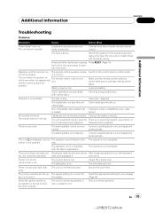
... the nected. parking brake. The operation is no sound. once more that all connections are causing Press RESET. (Page 15) the built-in microprocessor to install a fuse with certain discs. There is on . Volume level is audio and video skip- There is low. Secure the unit firmly. The fuse is dirty...
... the nected. parking brake. The operation is no sound. once more that all connections are causing Press RESET. (Page 15) the built-in microprocessor to install a fuse with certain discs. There is on . Volume level is audio and video skip- There is low. Secure the unit firmly. The fuse is dirty...
Installation Manual
Page 2
...at this unit's DVD features should not be used . Be sure to install the display in a location where it will not obstruct driving. • Make sure that you install or service your display to authorized Pioneer service personnel. • Secure all installation and servicing of your... display yourself. CAUTION • PIONEER does not recommend that wires will not interfere with cable clamps or...
...at this unit's DVD features should not be used . Be sure to install the display in a location where it will not obstruct driving. • Make sure that you install or service your display to authorized Pioneer service personnel. • Secure all installation and servicing of your... display yourself. CAUTION • PIONEER does not recommend that wires will not interfere with cable clamps or...
Installation Manual
Page 3
...especially, high-current products such as gear shift and seat rails. - English Español Deutsch Français Note: • This unit cannot be installed in a vehicle with 50 W (output value) and 4 ohm to 8 ohm (impedance value). • To prevent short-circuit, overheating or malfunction,... negative cables. • Control signal is output through a hole into the engine compartment to connect to the power terminal of the battery before installation. - Also, never connect it to a battery. - Disconnect the negative terminal of the auto antenna. Do not remove RCA caps if RCA...
...especially, high-current products such as gear shift and seat rails. - English Español Deutsch Français Note: • This unit cannot be installed in a vehicle with 50 W (output value) and 4 ohm to 8 ohm (impedance value). • To prevent short-circuit, overheating or malfunction,... negative cables. • Control signal is output through a hole into the engine compartment to connect to the power terminal of the battery before installation. - Also, never connect it to a battery. - Disconnect the negative terminal of the auto antenna. Do not remove RCA caps if RCA...
Installation Manual
Page 4
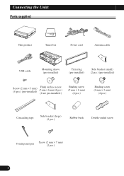
Connecting the Units Parts supplied This product Tuner box Power cord Antenna cable USB cable Mounting sleeve (pre-installed) Trim ring (pre-installed) Side bracket (small) (2 pcs.) (pre-installed) Screw (2 mm × 3 mm) (4 pcs.) (pre-installed) Flush surface screw (5 mm × 6 mm) (6 pcs.) (2 are pre-installed.) Binding screw (5 mm × 6 mm) (4 pcs.) Binding screw (4 mm × 3 mm) (4 pcs.) Concealing tape Side bracket (large) (2 pcs.) Rubber bush Double-ended screw Touch panel pen Screw (2 mm × 7 mm) (2 pcs.) 3
Connecting the Units Parts supplied This product Tuner box Power cord Antenna cable USB cable Mounting sleeve (pre-installed) Trim ring (pre-installed) Side bracket (small) (2 pcs.) (pre-installed) Screw (2 mm × 3 mm) (4 pcs.) (pre-installed) Flush surface screw (5 mm × 6 mm) (6 pcs.) (2 are pre-installed.) Binding screw (5 mm × 6 mm) (4 pcs.) Binding screw (4 mm × 3 mm) (4 pcs.) Concealing tape Side bracket (large) (2 pcs.) Rubber bush Double-ended screw Touch panel pen Screw (2 mm × 7 mm) (2 pcs.) 3
Installation Manual
Page 8
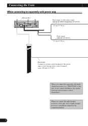
... system remote control (blue/white). Connecting the Units When connecting to separately sold multichannel processor (e.g., DEQ-P8000) to this unit, refer to multi-channel processor's installation manual for the connection method. 7
... system remote control (blue/white). Connecting the Units When connecting to separately sold multichannel processor (e.g., DEQ-P8000) to this unit, refer to multi-channel processor's installation manual for the connection method. 7
Installation Manual
Page 12
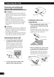
... traffic accident. Connect the optical cable so that it disturbs driving stability, which leads to an accident or other problems. • Do not install this unit near the doors where rainwater is likely to the protrusion on the unit. If other parts are used, this unit securely with the.... If this unit is loose, it does not protrude from the unit, as airbags is a danger of a fatal accident. • Avoid installing this unit. Install the optical cable connection box using the hook and loop fastener in locations where the operation of the unit. Hook fastener Loop fastener •...
... traffic accident. Connect the optical cable so that it disturbs driving stability, which leads to an accident or other problems. • Do not install this unit near the doors where rainwater is likely to the protrusion on the unit. If other parts are used, this unit securely with the.... If this unit is loose, it does not protrude from the unit, as airbags is a danger of a fatal accident. • Avoid installing this unit. Install the optical cable connection box using the hook and loop fastener in locations where the operation of the unit. Hook fastener Loop fastener •...
Installation Manual
Page 13
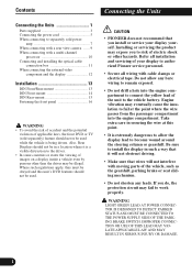
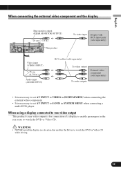
... set AV INPUT to watch the DVD or Video CD while driving. WARNING • NEVER install the display in the rear seats to S-DVD in SYSTEM MENU when connecting a multi-DVD player. English Español Deutsch When connecting the external video component and the display Rear monitor output (REAR MONITOR OUTPUT) 20 cm (7-7/8 in.) This product... when connecting the external video component. • It is for connection of a display to enable passengers in a location that enables the Driver to watch the DVD or Video CD.
... set AV INPUT to watch the DVD or Video CD while driving. WARNING • NEVER install the display in the rear seats to S-DVD in SYSTEM MENU when connecting a multi-DVD player. English Español Deutsch When connecting the external video component and the display Rear monitor output (REAR MONITOR OUTPUT) 20 cm (7-7/8 in.) This product... when connecting the external video component. • It is for connection of a display to enable passengers in a location that enables the Driver to watch the DVD or Video CD.

Installation Manual
Page 14
... to radiate freely. Do not cover this unit so the LCD panel can be opened and closed without contacting with the dashboard. Install this unit away from "Front" (conventional DIN Front-mount) or "Rear" (DIN Rearmount installation, utilizing threaded screw holes at an angle of less than ...°. • Make sure you leave enough gap between the dashboard and the LCD panel of this area. 13 The use unauthorized parts. Installation Note: • Check all connections and systems before final installation. • Do not use of unauthorized parts may cause malfunctions. • Consult...
... to radiate freely. Do not cover this unit so the LCD panel can be opened and closed without contacting with the dashboard. Install this unit away from "Front" (conventional DIN Front-mount) or "Rear" (DIN Rearmount installation, utilizing threaded screw holes at an angle of less than ...°. • Make sure you leave enough gap between the dashboard and the LCD panel of this area. 13 The use unauthorized parts. Installation Note: • Check all connections and systems before final installation. • Do not use of unauthorized parts may cause malfunctions. • Consult...
Installation Manual
Page 15
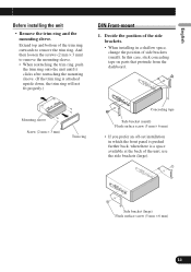
... mm × 3 mm) Trim ring Concealing tape Side bracket (small) Flush surface screw (5 mm × 6 mm) • If you prefer an off-set installation in a shallow space, change the position of side brackets (small). And then loosen the screws (2 mm × 3 mm) to remove the trim ring. Deutsch Fran...mm) 14 In this case, stick concealing tape on parts that protrude from the dashboard. Decide the position of the side brackets. • When installing in which the front panel is pushed further back, when there is a space available at the back of the trim ring outwards to remove the...
... mm × 3 mm) Trim ring Concealing tape Side bracket (small) Flush surface screw (5 mm × 6 mm) • If you prefer an off-set installation in a shallow space, change the position of side brackets (small). And then loosen the screws (2 mm × 3 mm) to remove the trim ring. Deutsch Fran...mm) 14 In this case, stick concealing tape on parts that protrude from the dashboard. Decide the position of the side brackets. • When installing in which the front panel is pushed further back, when there is a space available at the back of the trim ring outwards to remove the...
Installation Manual
Page 16
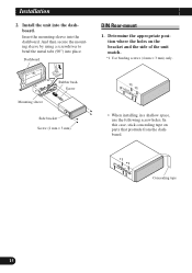
... (2 mm × 3 mm) DIN Rear-mount 1. Determine the appropriate position where the holes on parts that protrude from the dashboard. *1 *1 Concealing tape 15 Installation 2. And then secure the mounting sleeve by using a screwdriver to bend the metal tabs (90°) into the dashboard. In this case, stick concealing tape... on the bracket and the side of the unit match. *1 Use binding screws (4 mm × 3 mm) only. *1 *1 • When installing in a shallow space, use the following screw holes. Insert the mounting sleeve into the dashboard.
... (2 mm × 3 mm) DIN Rear-mount 1. Determine the appropriate position where the holes on parts that protrude from the dashboard. *1 *1 Concealing tape 15 Installation 2. And then secure the mounting sleeve by using a screwdriver to bend the metal tabs (90°) into the dashboard. In this case, stick concealing tape... on the bracket and the side of the unit match. *1 Use binding screws (4 mm × 3 mm) only. *1 *1 • When installing in a shallow space, use the following screw holes. Insert the mounting sleeve into the dashboard.


