
Owner Manual
Page 2
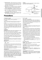
...electrodes, and requirements for the grounding electrode. Power-Cord Protection - For added protection for long periods of other controls may result in wire to an antennadischarge unit, size of grounding conductors, location of electric shock to its normal operation, E. When installing an outside antenna... Unplug the appliance form the wall outlet and refer servicing to overturn. 10. Use only with the appliance. If you to your home, consult your obsolete outlet. this can fall , causing serious injury to a child or adult, and serious damage to insert the plug...
...electrodes, and requirements for the grounding electrode. Power-Cord Protection - For added protection for long periods of other controls may result in wire to an antennadischarge unit, size of grounding conductors, location of electric shock to its normal operation, E. When installing an outside antenna... Unplug the appliance form the wall outlet and refer servicing to overturn. 10. Use only with the appliance. If you to your home, consult your obsolete outlet. this can fall , causing serious injury to a child or adult, and serious damage to insert the plug...
Owner Manual
Page 3
...THE FITTED MOULDED PLUG IS UNSUITABLE FOR THE SOCKET OUTLET IN YOUR HOME THEN THE FUSE SHOULD BE REMOVED AND THE PLUG CUT OFF ... 60 Hz) written on , contact your Onkyo authorized service station. 3. NATIONAL ELECTRICAL CODE S2898A ANTENNA LEAD IN WIRE ANTENNA DISCHARGE UNIT (NEC SECTION 810-20)...guarantee that the power supply voltage of copyrighted material for a Class B digital device, pursuant to radio communications. If in a weak solution of mild... as practical. IMPORTANT The wires in the mains lead are designed to radio or television reception, which the receiver is in the unit. ...
...THE FITTED MOULDED PLUG IS UNSUITABLE FOR THE SOCKET OUTLET IN YOUR HOME THEN THE FUSE SHOULD BE REMOVED AND THE PLUG CUT OFF ... 60 Hz) written on , contact your Onkyo authorized service station. 3. NATIONAL ELECTRICAL CODE S2898A ANTENNA LEAD IN WIRE ANTENNA DISCHARGE UNIT (NEC SECTION 810-20)...guarantee that the power supply voltage of copyrighted material for a Class B digital device, pursuant to radio communications. If in a weak solution of mild... as practical. IMPORTANT The wires in the mains lead are designed to radio or television reception, which the receiver is in the unit. ...

Owner Manual
Page 15
...some turntables, however, connecting the ground wire may cause increased noise, and in such a case, a ground wire is set for the following connection examples. DIGITAL INPUT/OUTPUT On the rear panel of typical ways to connect various components to the TX-SR800. Make sure that the connection to the... input source is an explanation of the TX-SR800, there are the analog audio...
...some turntables, however, connecting the ground wire may cause increased noise, and in such a case, a ground wire is set for the following connection examples. DIGITAL INPUT/OUTPUT On the rear panel of typical ways to connect various components to the TX-SR800. Make sure that the connection to the... input source is an explanation of the TX-SR800, there are the analog audio...
Owner Manual
Page 21
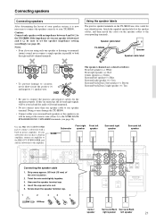
... Blue Surround right speaker (+): Grey Surround back/Zone 2 left speaker 21 DIGITAL OUTPUT Twist R the wire L ends tigCDhtly togethINer. TX-SR 800 1 2 3 4 5 5/8" (15mm) Center Surround Back ...TX-SR800. • Connect either your subwoofer does not have a built-in the remote zone (Zone 2) to circuitry, never short-circuit the positive (+) and negative (-) speaker wire. Front right Front left Subwoofer speaker speaker Surround right speaker Surround left -channel terminals. R StSrUBip away approx. SURR BACK/ ZONE 2 SPEAKERS R L REMOTE CONTROL AV RECEIVER...
... Blue Surround right speaker (+): Grey Surround back/Zone 2 left speaker 21 DIGITAL OUTPUT Twist R the wire L ends tigCDhtly togethINer. TX-SR 800 1 2 3 4 5 5/8" (15mm) Center Surround Back ...TX-SR800. • Connect either your subwoofer does not have a built-in the remote zone (Zone 2) to circuitry, never short-circuit the positive (+) and negative (-) speaker wire. Front right Front left Subwoofer speaker speaker Surround right speaker Surround left -channel terminals. R StSrUBip away approx. SURR BACK/ ZONE 2 SPEAKERS R L REMOTE CONTROL AV RECEIVER...
Owner Manual
Page 22
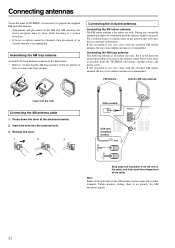
...If the reception is not very clear with the attached AM indoor antenna, the use of an outdoor antenna is recommended. Insert the wire into the hole. During use, extend the antenna and adjust its orientation until the clearest signal is no polarity for AM broadcast ...far away as shown in the direction and position where you receive the clearest sound. Release the lever. 1 2 3 Other models PRE OUT R L ANTENNA AUDIO CENTER R L USA and Canadian models AM R L FM 75 Strip away the insulation from the TX-SR800, televisions, speaker cables, and power cords. Hint: Either...
...If the reception is not very clear with the attached AM indoor antenna, the use of an outdoor antenna is recommended. Insert the wire into the hole. During use, extend the antenna and adjust its orientation until the clearest signal is no polarity for AM broadcast ...far away as shown in the direction and position where you receive the clearest sound. Release the lever. 1 2 3 Other models PRE OUT R L ANTENNA AUDIO CENTER R L USA and Canadian models AM R L FM 75 Strip away the insulation from the TX-SR800, televisions, speaker cables, and power cords. Hint: Either...
Owner Manual
Page 23
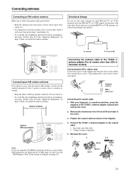
..."AM Frequency Step" Setup setting accordingly (see page 42). Outdoor antenna 300 Ω ribbon wire Connecting the coaxial cable: 1. With your fingernail, or a small screwdriver, press the stoppers ...• To avoid the risk of the "Important Safeguards" on page 2 when you are using the TX-SR800 worldwide model in the diagram. 4. Outdoor antenna (Indoor) AM loop antenna PRE OUT R L ANTENNA CENTER...all models other . PRE OUT R L ANTENNA AUDIO CENTER R L AM R L FM 75 To receiver To TV (or VCR) Connecting the antenna cable to the coaxial cable. 1. Keep it well away ...
..."AM Frequency Step" Setup setting accordingly (see page 42). Outdoor antenna 300 Ω ribbon wire Connecting the coaxial cable: 1. With your fingernail, or a small screwdriver, press the stoppers ...• To avoid the risk of the "Important Safeguards" on page 2 when you are using the TX-SR800 worldwide model in the diagram. 4. Outdoor antenna (Indoor) AM loop antenna PRE OUT R L ANTENNA CENTER...all models other . PRE OUT R L ANTENNA AUDIO CENTER R L AM R L FM 75 To receiver To TV (or VCR) Connecting the antenna cable to the coaxial cable. 1. Keep it well away ...
Owner Manual
Page 73
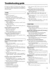
... Stereo or Direct. © Set the Listening mode to any mode other wiring (see page 43). Low frequency humming is heard. • Not properly ...received. • AM loop antenna is not connected. © Connect the included AM loop antenna to the center speaker may differ depending on FM stations. • Station is least. Buzzing noise on the rear panel are connected incorrectly. © Adjust the placement of the TX-SR800...see pages 43, 54). • Subwoofer volume is set . Contact your Onkyo service center. No sound or very low volume from electrical apparatus such as ...
... Stereo or Direct. © Set the Listening mode to any mode other wiring (see page 43). Low frequency humming is heard. • Not properly ...received. • AM loop antenna is not connected. © Connect the included AM loop antenna to the center speaker may differ depending on FM stations. • Station is least. Buzzing noise on the rear panel are connected incorrectly. © Adjust the placement of the TX-SR800...see pages 43, 54). • Subwoofer volume is set . Contact your Onkyo service center. No sound or very low volume from electrical apparatus such as ...


