
Service Manual
Page 1
Copyright 1997, Okidata, Division of the Okidata Service Training Manual was built with the pictures rendered at 300 dpi, which is ideal for any updates to this material. (http://bpx.okidata.com) All rights reserved. See the OKIDATA Business Partner Exchange (BPX) for printing, but does not view on most displays well. Service Guide OL1200 Chapter 0 About This Manual Page: 1 OL1200 LED Page Printer Adobe Acrobat printable reference copy of the OKIDATA Service Training Manual. 09/17/97 Note: This Adobe Acrobat version of OKI America, Inc.
Copyright 1997, Okidata, Division of the Okidata Service Training Manual was built with the pictures rendered at 300 dpi, which is ideal for any updates to this material. (http://bpx.okidata.com) All rights reserved. See the OKIDATA Business Partner Exchange (BPX) for printing, but does not view on most displays well. Service Guide OL1200 Chapter 0 About This Manual Page: 1 OL1200 LED Page Printer Adobe Acrobat printable reference copy of the OKIDATA Service Training Manual. 09/17/97 Note: This Adobe Acrobat version of OKI America, Inc.
Service Manual
Page 2
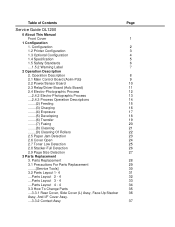
Table of Contents Service Guide OL1200 0 About This Manual Front Cover 1 Configuration 1. Operation Description 2.1 Main Control Board (Aolm-Pcb) 2.2 Power/Sensor Board 2.3 Relay/Driver Board (Aolc Board) 2.4 Electro-Photographic Process ....2.4.2 Electro-Photographic Process ....2.4.3 Process ...
Table of Contents Service Guide OL1200 0 About This Manual Front Cover 1 Configuration 1. Operation Description 2.1 Main Control Board (Aolm-Pcb) 2.2 Power/Sensor Board 2.3 Relay/Driver Board (Aolc Board) 2.4 Electro-Photographic Process ....2.4.2 Electro-Photographic Process ....2.4.3 Process ...

Service Manual
Page 3
... 62 63 64 65 66 67 68 69 70 71 72 73 74 75 76 77 78 79 80 Table of Contents ....3.3.3 Dc Fan Motor ....3.3.4 Manual Feed Hopper Assy ....3.3.5 Side Cover (R) (Operator Panel Assy) ....3.3.6 Earth Plate Bk (R) (Aolm-Pcb, Ic Cover) ....3.3.7 Stacker Cover Assy, Damper Arm, And Washer ....3.3.8 Damper ....3.3.9 Stacker Full...
... 62 63 64 65 66 67 68 69 70 71 72 73 74 75 76 77 78 79 80 Table of Contents ....3.3.3 Dc Fan Motor ....3.3.4 Manual Feed Hopper Assy ....3.3.5 Side Cover (R) (Operator Panel Assy) ....3.3.6 Earth Plate Bk (R) (Aolm-Pcb, Ic Cover) ....3.3.7 Stacker Cover Assy, Damper Arm, And Washer ....3.3.8 Damper ....3.3.9 Stacker Full...

Service Manual
Page 12
... operation: 50 to 90°F (10 to 32°C) In storage: 14 to 110°F (10 to 105 g/m 2 ) Manual feed: Label, OHP paper (transparency) Envelope (6) Printing speed First print: 12 sec. Service Guide OL1200 Chapter 1 Configuration Page: 5 1.4 Specification (1) Type Desk top (2) External dimensions Height 10.6 (270 mm) (excludes protruding Width 14.4 (366...
... operation: 50 to 90°F (10 to 32°C) In storage: 14 to 110°F (10 to 105 g/m 2 ) Manual feed: Label, OHP paper (transparency) Envelope (6) Printing speed First print: 12 sec. Service Guide OL1200 Chapter 1 Configuration Page: 5 1.4 Specification (1) Type Desk top (2) External dimensions Height 10.6 (270 mm) (excludes protruding Width 14.4 (366...

Service Manual
Page 20
... serial interface conforming to EIA RS232C. - This mode can provide the bidirectional operation in Fig. 2-2. (For the electrical/physical characteristics of the interface, see the OKI HSP interface technical manual. The change to another mode from the compatibility mode is made through negotiation. (When the BI DIRECTION is an...
... serial interface conforming to EIA RS232C. - This mode can provide the bidirectional operation in Fig. 2-2. (For the electrical/physical characteristics of the interface, see the OKI HSP interface technical manual. The change to another mode from the compatibility mode is made through negotiation. (When the BI DIRECTION is an...

Service Manual
Page 41
.... - At power-on time and during printing. After hopping operation is placed at the paper sensor. - The paper size check with the manual feed specified considers the reference size as free size. If any of error - The trailing part of the paper does not pass over the ...does not reach the outlet sensor within a predetermined distance after the leading part of the paper does not reach the inlet sensor. - Service Guide OL1200 Chapter 2 Operation Description Page: 23 2.5 Paper Jam Detection The paper jam detection function supervises the paper state at power-on time, the paper ...
.... - At power-on time and during printing. After hopping operation is placed at the paper sensor. - The paper size check with the manual feed specified considers the reference size as free size. If any of error - The trailing part of the paper does not pass over the ...does not reach the outlet sensor within a predetermined distance after the leading part of the paper does not reach the inlet sensor. - Service Guide OL1200 Chapter 2 Operation Description Page: 23 2.5 Paper Jam Detection The paper jam detection function supervises the paper state at power-on time, the paper ...

Service Manual
Page 42
... (BPX) for any updates to this material. (http://bpx.okidata.com) Paper size error Paper size error - The paper size check with the manual feed specified considers the reference size as free size. The inlet sensor 2 detects that the paper does not pass over the inlet sensor 1 within ...predetermined range of OKI America, Inc. All rights reserved. Copyright 1997, Okidata, Division of distance. - It is detected that the size of the paper is A4 or ...
... (BPX) for any updates to this material. (http://bpx.okidata.com) Paper size error Paper size error - The paper size check with the manual feed specified considers the reference size as free size. The inlet sensor 2 detects that the paper does not pass over the inlet sensor 1 within ...predetermined range of OKI America, Inc. All rights reserved. Copyright 1997, Okidata, Division of distance. - It is detected that the size of the paper is A4 or ...
Service Manual
Page 56
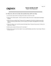
... 1. Remove three screws 4. Disconnect the engagement at the left and right protrusions 8A . Remove the I /F cover Assy. (1) Turn the AC power switch off. Service Guide OL1200 Chapter 3 Parts Replacement Page: 36 3.3.1 Rear cover, side cover (L) Assy, face-up stacker Assy 8. Remove the side cover (L) Assy 5. (5) Remove two screws 6. Unplug the AC...
... 1. Remove three screws 4. Disconnect the engagement at the left and right protrusions 8A . Remove the I /F cover Assy. (1) Turn the AC power switch off. Service Guide OL1200 Chapter 3 Parts Replacement Page: 36 3.3.1 Rear cover, side cover (L) Assy, face-up stacker Assy 8. Remove the side cover (L) Assy 5. (5) Remove two screws 6. Unplug the AC...

Service Manual
Page 60
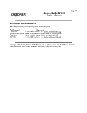
Disengage the lower portion of OKI America, Inc. Copyright 1997, Okidata, Division of this material. (http://bpx.okidata.com) Unplug the AC power cord from the outlet. (2) Open manual feed hopper Assy 1. All rights reserved. See the OKIDATA Business Partner Exchange (BPX) for any updates to this Assy. (3) Hold manual feed hopper Assy 1 vertically and remove the left and right levers 2 with a downward motion. Service Guide OL1200 Chapter 3 Parts Replacement Page: 39 3.3.4 Manual feed hopper Assy (1) Turn the AC power switch off.
Disengage the lower portion of OKI America, Inc. Copyright 1997, Okidata, Division of this material. (http://bpx.okidata.com) Unplug the AC power cord from the outlet. (2) Open manual feed hopper Assy 1. All rights reserved. See the OKIDATA Business Partner Exchange (BPX) for any updates to this Assy. (3) Hold manual feed hopper Assy 1 vertically and remove the left and right levers 2 with a downward motion. Service Guide OL1200 Chapter 3 Parts Replacement Page: 39 3.3.4 Manual feed hopper Assy (1) Turn the AC power switch off.

Service Manual
Page 61
... outlet. (2) Remove interface cable 1. (3) Open stacker cover 2. Service Guide OL1200 Chapter 3 Parts Replacement Page: 40 3.3.5 Side cover (R) (operator panel Assy) (1) Turn the AC power switch off. Remove two screws 3. Copyright 1997, Okidata, Division of OKI America, Inc. Remove operator panel Assy 7. (5) Open manual feed hopper Assy 8. Remove three screws 9 and then remove side...
... outlet. (2) Remove interface cable 1. (3) Open stacker cover 2. Service Guide OL1200 Chapter 3 Parts Replacement Page: 40 3.3.5 Side cover (R) (operator panel Assy) (1) Turn the AC power switch off. Remove two screws 3. Copyright 1997, Okidata, Division of OKI America, Inc. Remove operator panel Assy 7. (5) Open manual feed hopper Assy 8. Remove three screws 9 and then remove side...

Service Manual
Page 73
Service Guide OL1200 Chapter 3 Parts Replacement Page: 48 3.3.13 Separator F (1) Turn the AC power switch off. Unplug the AC power cord from square-shaped connector 6. (8) Turn idle gear 8 ... torsion spring. (6) Remove two screws 5 and then remove square-shaped connector 6. (7) Using great care, remove the connector of switch Assy 7 from the outlet. (2) Remove the manual feed hopper Assy (see 3.3.4). (3) Remove the side cover (R) (see 3.3.5). (4) Remove the front feeder Assy (see 3.3.12 steps (1) to lose the springs. (10) Remove four screws...
Service Guide OL1200 Chapter 3 Parts Replacement Page: 48 3.3.13 Separator F (1) Turn the AC power switch off. Unplug the AC power cord from square-shaped connector 6. (8) Turn idle gear 8 ... torsion spring. (6) Remove two screws 5 and then remove square-shaped connector 6. (7) Using great care, remove the connector of switch Assy 7 from the outlet. (2) Remove the manual feed hopper Assy (see 3.3.4). (3) Remove the side cover (R) (see 3.3.5). (4) Remove the front feeder Assy (see 3.3.12 steps (1) to lose the springs. (10) Remove four screws...

Service Manual
Page 75
Service Guide OL1200 Chapter 3 Parts Replacement Page: 49 3.3.14 Front feeder roller Assy (1) Turn the AC power supply switch off. Unplug the AC power cord from the right ... spring B. (At this time, the bearing C on the left (L) side is also removed.) Do not mix these parts with those from the outlet. (2) Remove the manual feed hopper Assy (see 3.3.4). (3) Remove the side cover (R) (see 3.3.5). (4) Remove the front feeder roller Assy (see 3.3.12 (1) to (3). (5) Remove the paper supply guide A (see 3.3.13...
Service Guide OL1200 Chapter 3 Parts Replacement Page: 49 3.3.14 Front feeder roller Assy (1) Turn the AC power supply switch off. Unplug the AC power cord from the right ... spring B. (At this time, the bearing C on the left (L) side is also removed.) Do not mix these parts with those from the outlet. (2) Remove the manual feed hopper Assy (see 3.3.4). (3) Remove the side cover (R) (see 3.3.5). (4) Remove the front feeder roller Assy (see 3.3.12 (1) to (3). (5) Remove the paper supply guide A (see 3.3.13...

Service Manual
Page 77
Service Guide OL1200 Chapter 3 Parts Replacement Page: 50 3.3.15 Hopping motor (1) Turn the AC power switch off. Unplug the AC power cable from the outlet. (2) Remove the manual feed hopper Assy (see 3.3.4). (3) Remove the side cover (R) (see 3.3.5). (4) Remove the front feeder Assy (see 3.3.12.(1) to (3)). (5) Remove the inner cover and square-shaped connector...
Service Guide OL1200 Chapter 3 Parts Replacement Page: 50 3.3.15 Hopping motor (1) Turn the AC power switch off. Unplug the AC power cable from the outlet. (2) Remove the manual feed hopper Assy (see 3.3.4). (3) Remove the side cover (R) (see 3.3.5). (4) Remove the front feeder Assy (see 3.3.12.(1) to (3)). (5) Remove the inner cover and square-shaped connector...

Service Manual
Page 79
Note: Use great care when removing the sensor. Unplug the AC power cord from the outlet. (2) Remove the manual feed hopper Assy (see 3.3.4). (3) Remove the side cover (R) (see 3.3.5). (4) Remove the front feeder roller Assy (see 3.3.12. (1) to (3)). (5) Remove the side plate (R) Assy (see 3.3.15. (1) ... claws and then remove front feeder paper end sensor 1. (10) Remove two screws 5 and then remove square-shaped connector 6 from paper supply guide C (3). Service Guide OL1200 Chapter 3 Parts Replacement Page: 51 3.3.16 Front feeder paper end sensor (1) Turn the AC power switch off.
Note: Use great care when removing the sensor. Unplug the AC power cord from the outlet. (2) Remove the manual feed hopper Assy (see 3.3.4). (3) Remove the side cover (R) (see 3.3.5). (4) Remove the front feeder roller Assy (see 3.3.12. (1) to (3)). (5) Remove the side plate (R) Assy (see 3.3.15. (1) ... claws and then remove front feeder paper end sensor 1. (10) Remove two screws 5 and then remove square-shaped connector 6 from paper supply guide C (3). Service Guide OL1200 Chapter 3 Parts Replacement Page: 51 3.3.16 Front feeder paper end sensor (1) Turn the AC power switch off.

Service Manual
Page 81
... front feeder roller Assy (see 3.3.12, (1) to unlock it. Remove gear (TR) 1 and transfer roller 2. (At this time, it is not required to remove the manual feed hopper Assy. (8) Remove the earth plate (HP). (9) Lift gear (TR) 1 to (3)) . At this time, two bearings (TR) 3 and two transfer springs 4 are also removed... and then remove two connectors 6 and 7. (11) Remove the DC Fan motor. (12) Remove eight screws 10 and then remove main chassis unit A. Service Guide OL1200 Chapter 3 Parts Replacement Page: 52 3.3.17 Main chassis unit (1) Turn the AC power switch off.
... front feeder roller Assy (see 3.3.12, (1) to unlock it. Remove gear (TR) 1 and transfer roller 2. (At this time, it is not required to remove the manual feed hopper Assy. (8) Remove the earth plate (HP). (9) Lift gear (TR) 1 to (3)) . At this time, two bearings (TR) 3 and two transfer springs 4 are also removed... and then remove two connectors 6 and 7. (11) Remove the DC Fan motor. (12) Remove eight screws 10 and then remove main chassis unit A. Service Guide OL1200 Chapter 3 Parts Replacement Page: 52 3.3.17 Main chassis unit (1) Turn the AC power switch off.

Service Manual
Page 113
Service Guide OL1200 Chapter 4 Adjustment Page: 74 4.1.1 User maintenance mode - All settings for all ...key. - This mode uses the menu for any updates to adjust the printing start position within the range of OKI America, Inc. Printing is turning the power OFF. (3) Drum counter reset - All rights reserved. The operation ...Copies and Paper Size). (5) X ADJUST - To exit from the host is less than one page, printing can be activated manually be pressing the Form Feed key after selecting the OFF LINE. (Automatic activation of resetting. (4) Operator panel menu disable - ...
Service Guide OL1200 Chapter 4 Adjustment Page: 74 4.1.1 User maintenance mode - All settings for all ...key. - This mode uses the menu for any updates to adjust the printing start position within the range of OKI America, Inc. Printing is turning the power OFF. (3) Drum counter reset - All rights reserved. The operation ...Copies and Paper Size). (5) X ADJUST - To exit from the host is less than one page, printing can be activated manually be pressing the Form Feed key after selecting the OFF LINE. (Automatic activation of resetting. (4) Operator panel menu disable - ...
Service Manual
Page 123
... Head Image Drum Cartridge Fuser Unit EEPROM Adjustment Set the LED head drive time. (Refer to Chapter 4.2.1) Reset the image drum counter. (Refer to User's manual) Reset the fuser counter. (Refer to Chapter 4.2.2) Set the LED head drive time. (Refer to this material. (http://bpx.okidata.com) Service Guide...
... Head Image Drum Cartridge Fuser Unit EEPROM Adjustment Set the LED head drive time. (Refer to Chapter 4.2.1) Reset the image drum counter. (Refer to User's manual) Reset the fuser counter. (Refer to Chapter 4.2.2) Set the LED head drive time. (Refer to this material. (http://bpx.okidata.com) Service Guide...
Service Manual
Page 132
...executed by "A4" depending on the lower line, "MANUAL LETTER REQUEST" is in the menu. Copyright 1997, Okidata, Division of paper into the manual feed slot or press the "FORM FEED" button on...the upper line will scroll one at least 2 seconds. Characters will stay fixed. Service Guide OL1200 Chapter 5 Periodic Maintenance Page: 88 5.2.2 Cleaning Page Function There is a Charge Roller cleaning function..., which can verify that the printer has entered the cleaning mode. (3) Insert a sheet of OKI America, Inc. The printer enters the cleaning mode. (2) The LCD displays "CLEANING" on the...
...executed by "A4" depending on the lower line, "MANUAL LETTER REQUEST" is in the menu. Copyright 1997, Okidata, Division of paper into the manual feed slot or press the "FORM FEED" button on...the upper line will scroll one at least 2 seconds. Characters will stay fixed. Service Guide OL1200 Chapter 5 Periodic Maintenance Page: 88 5.2.2 Cleaning Page Function There is a Charge Roller cleaning function..., which can verify that the printer has entered the cleaning mode. (3) Insert a sheet of OKI America, Inc. The printer enters the cleaning mode. (2) The LCD displays "CLEANING" on the...

Service Manual
Page 134
Service Guide OL1200 Chapter 6 Troubleshooting Procedures Page: 90 6.1 Troubleshooting Tips (1) Check the basic check points covered in the users manual. (2) Gather as much information on the problem from the customer as possible. (3) Perform inspections in conditions close to this material. (http://bpx.okidata.com) All rights reserved. See the OKIDATA Business Partner Exchange (BPX) for any updates to those in which the problem had occurred. Copyright 1997, Okidata, Division of OKI America, Inc.
Service Guide OL1200 Chapter 6 Troubleshooting Procedures Page: 90 6.1 Troubleshooting Tips (1) Check the basic check points covered in the users manual. (2) Gather as much information on the problem from the customer as possible. (3) Perform inspections in conditions close to this material. (http://bpx.okidata.com) All rights reserved. See the OKIDATA Business Partner Exchange (BPX) for any updates to those in which the problem had occurred. Copyright 1997, Okidata, Division of OKI America, Inc.

Service Manual
Page 140
...status The printer enters into this mode when the idle state continues for the period of time specified in the buffer. Service Guide OL1200 Chapter 6 Troubleshooting Procedures Page: 96 LCD Status Messages: (1-4) General Categor y Daily status LCD Status Message Daily status Trouble or Status...line mode. Normal operation xxx: Emulation in use (HP4, PS, HxD, AUT) Normal operation tttttt: Tray being selected (TRAY 1, TRAY 2, FRONT, MANUAL, ENVLOP) mmmmmmmmm: Paper size in the tray being selected (LETTER, EXECUTIVE, LEGAL 14, LEGAL 13,A4 SIZE, A5 SIZE, A6 SIZE, B5 SIZE...
...status The printer enters into this mode when the idle state continues for the period of time specified in the buffer. Service Guide OL1200 Chapter 6 Troubleshooting Procedures Page: 96 LCD Status Messages: (1-4) General Categor y Daily status LCD Status Message Daily status Trouble or Status...line mode. Normal operation xxx: Emulation in use (HP4, PS, HxD, AUT) Normal operation tttttt: Tray being selected (TRAY 1, TRAY 2, FRONT, MANUAL, ENVLOP) mmmmmmmmm: Paper size in the tray being selected (LETTER, EXECUTIVE, LEGAL 14, LEGAL 13,A4 SIZE, A5 SIZE, A6 SIZE, B5 SIZE...

